BNG Dual-Homing with EVPN VPWS in the Access Network and SRv6 Transport
This chapter describes BNG dual-homing with EVPN VPWS in the access network and SRv6 transport.
Topics in this chapter include:
Appendix with configuration files
Applicability
The information and configuration in this chapter is based on SR OS Release 22.10.R1. The feature described in this chapter applies to all FP4 and above based SR systems; it is not supported on VSR.
Enhanced subscriber management (ESM) is prerequisite knowledge. This chapter can serve as an SRv6 primer for subscriber management users who are less familiar with this technology.
Overview
Segment routing over IPv6 dataplane (SRv6) is a technology that supports overlay network designs over a single dataplane protocol (IPv6). The size of an IPv6 address (128 bits) is large enough to carry more information than only the addressing of interfaces on a network device. SRv6 allows for additional information so that an IPv6 address can encode functions that extend beyond simple node reachability information. Mature routing protocols (IGP and BGP) with proven fast rerouting mechanisms continue to be used to disseminate SRv6 information across the networks. The mix of those fast-rerouting mechanisms, SRv6, and synchronized subscribers in dual-homed environment enhanced subscriber management with multi-chassis synchronization (ESM MCS) results in simplified and robust access networks that benefit service providers and their customers.
This chapter describes an example topology with:
- redundant BNGs
- synchronized subscribers
- an SRv6-based network providing access to the subscribers
- routing on the core side where the cost of advertised subscriber routes depends on the forwarding state—specifically, the subscriber routed redundancy protocol (SRRP) state—in the access network
This chapter provides integrated configuration content for BNG and SRv6.
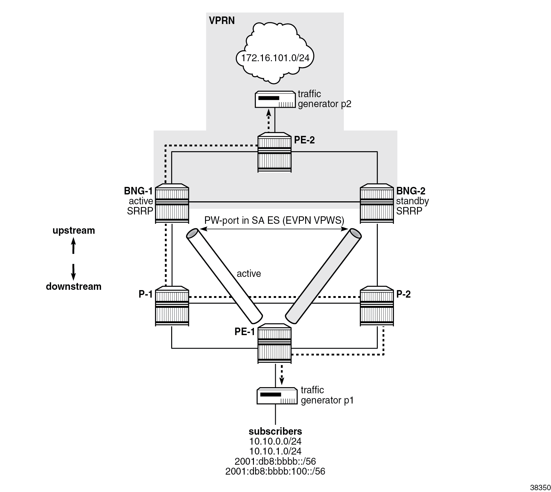
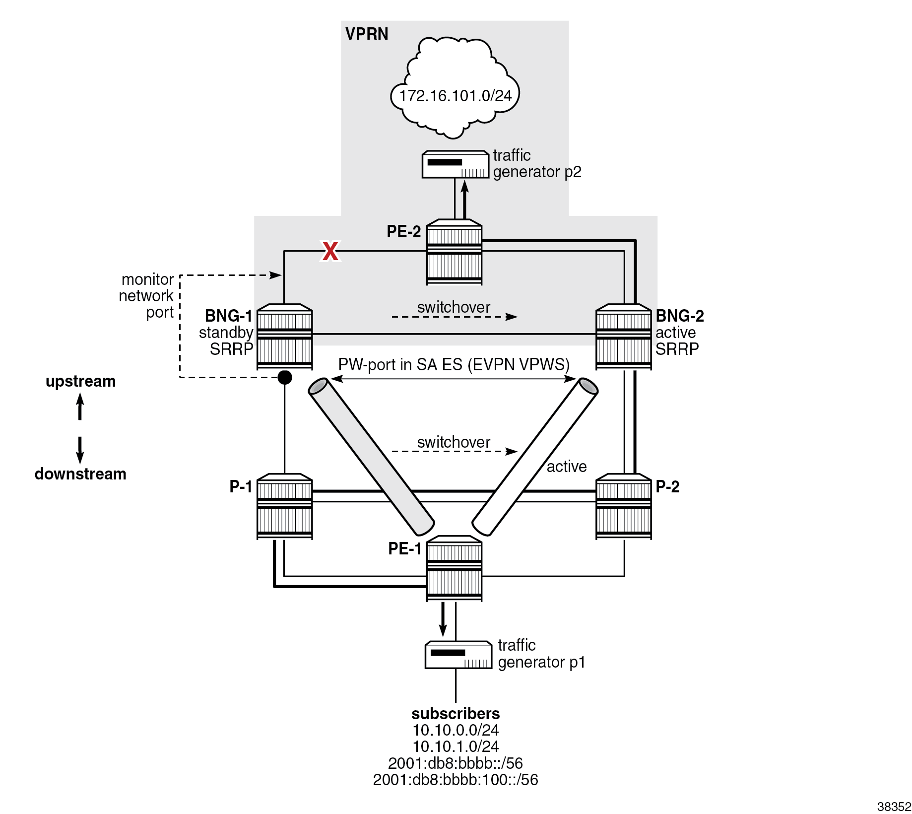
The figure Example topology shows the example topology used throughout this chapter. The terminology is as follows:
- The access network refers to all nodes downstream of the BNGs, including the interfaces and SAPs on the BNGs connected to that part of the network.
- The core part of the network refers to all nodes upstream of the BNGs, including the interfaces and SAPs on the BNGs connecting them to that part of the network.
- The term "EVPN VPWS" is used interchangeably with "Epipe" because the EVPN VPWS deployed in the access network is configured in SR OS nodes as an Epipe.
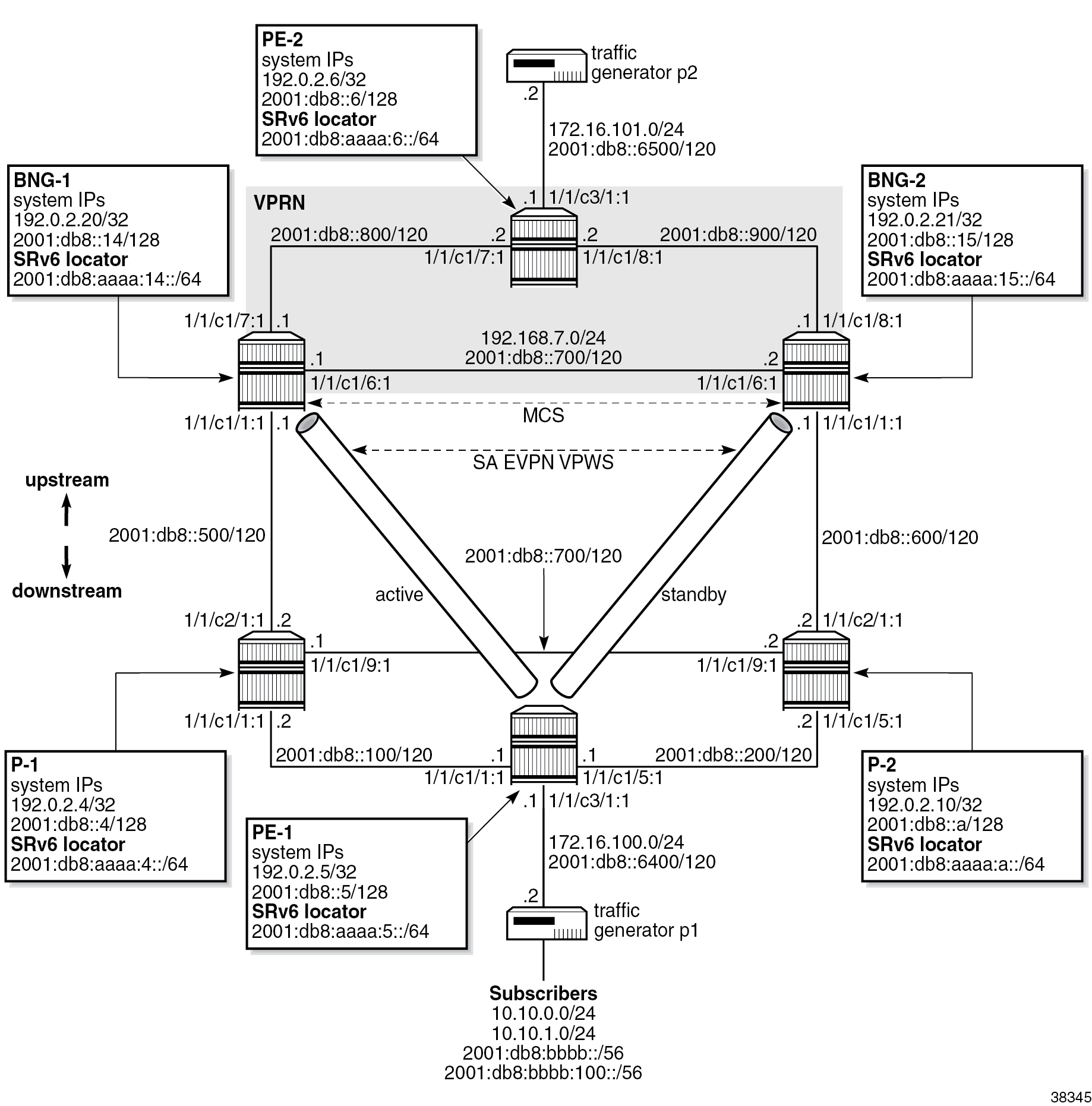
At a high level, the topology in the figure Example topology can be described in terms of access-related configuration, subscriber-related configuration, and core-related configuration.
Access-related configuration
- Subscribers are connected to the first-mile access node (PE-1), which is dual-homed to the two BNGs (BNG-1 and BNG-2).
- Pseudowire (PW) ports on the two BNGs are part of an Ethernet segment (ES) configured in single-active (SA) mode in the EVPN VPWS multihoming (MH) environment.
- The EVPN transport technology in the access network is SRv6.
Subscriber-related configuration
- There are 10 IPoE and 10 PPPoE dual-stack sessions terminated on a PW-SAP in a VPRN on both BNGs.
- Each IPoE and PPPoE session has an IPv4 address, a DHCPv6 identity association for non-temporary addresses (IA-NA), and a DHCPv4 identity association for prefix delegation (IA-PD) addresses. IA-PD addresses are modeled as managed routes with IPv6 next hops.
- Each session is mapped to a separate subscriber.
- Subscriber sessions are synchronized between the two BNGs. A fully synchronized model offers redundancy protection with minimal loss during network outages.
- DHCPv4/v6 servers are instantiated on the BNGs and their pools are synchronized, except for DHCPv4 pools used for internal address assignment to PPPoEv4 sessions. IPv4 addresses for PPPoEv4 sessions are synchronized in DHCPv4 pools through PPPoE session synchronization and not directly through DHCP pools.
- The SRRP state is indirectly derived from the state of the dual-homed EVPN ES in the access network and does not rely on exchange of SRRP keepalive messages between the two BNGs.
- A redundant interface between the two BNGs provides a temporary path for subscriber traffic while the network is converging during switchovers.
Core-related configuration
- A VPRN with SRv6 transport is deployed in the core.
- SRRP-aware routing on the core side ensures that the core traffic follows the BNG with the active SRRP instance. In other words, traffic in both directions (upstream and downstream) is attracted to one BNG or the other based on the SRRP state.
The example topology provides protection against failures of network elements in the access and core networks, including the BNGs themselves.
Subscriber traffic is run between two ports of a traffic generator. For topology verification purposes, network failures are purposefully introduced and their effect on the subscriber traffic is examined.
Subscriber synchronization
The subscriber state is synchronized between the two BNGs, including DHCPv4/v6 lease state and PPPoEv4/v6 states.
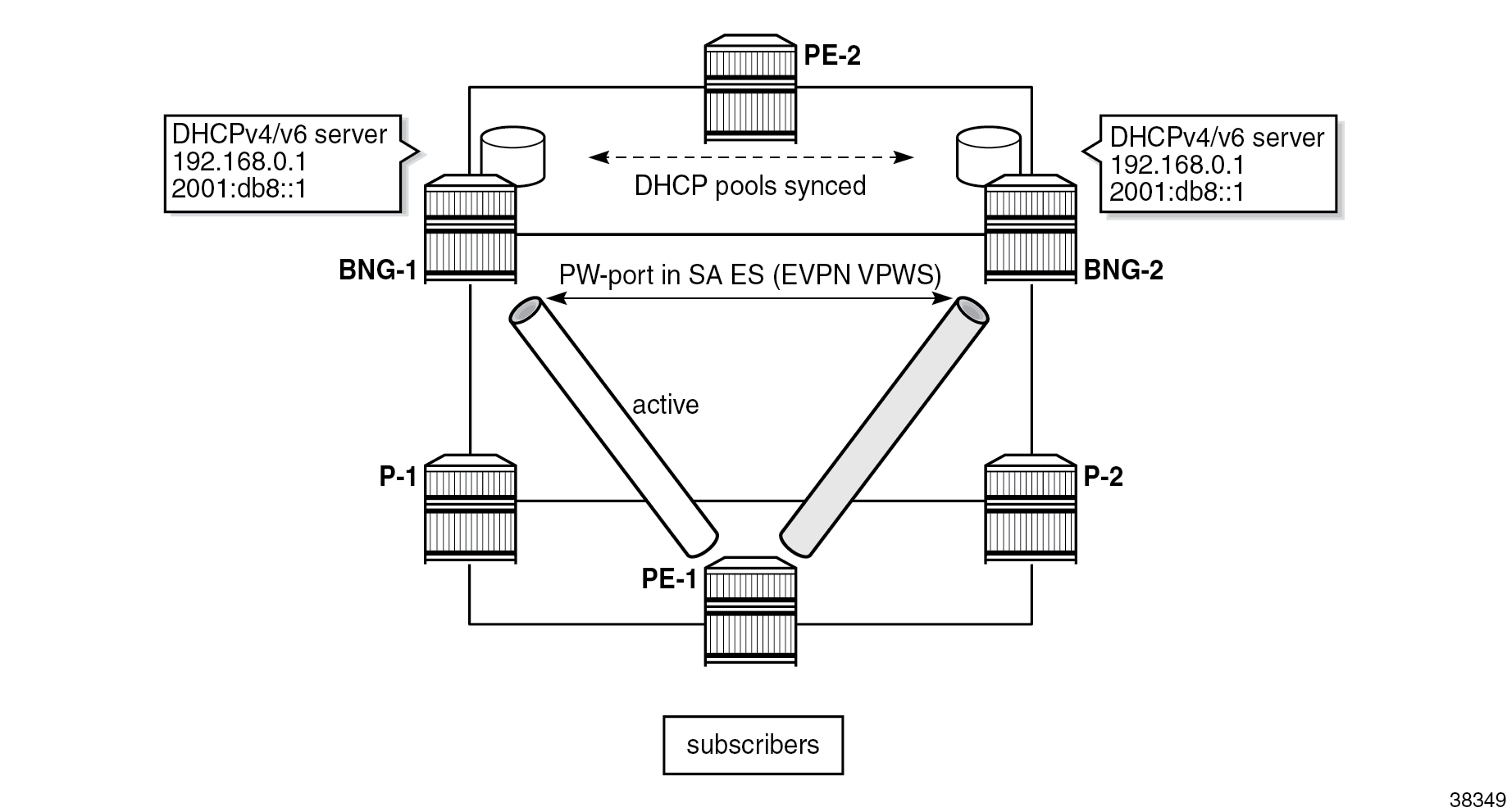
DHCPv4/v6 pools on the local DHCP servers in both BNGs are synchronized in access-driven mode (except for the pools used for internal IP address allocation to PPPoEv4, which are synchronized indirectly through PPPoE session synchronization). In access driven mode, the DHCPv4/v6 servers in each BNG are configured identically and are attached to an interface with the same IP address. Both servers can allocate IP addresses at any time; however, to prevent duplication of IP addresses, access to only one server is allowed at any given time. This restriction is achieved through the redundancy model, which relies on the SA mode of operation on the ES coupled with SRRP.
The figure DHCP pool synchronization in access-driven mode shows a topology using the redundancy model, where subscribers have access only to BNG-1 via EVPN VPWS multihoming. The path of the EVPN VPWS on the left side is active while the path on the right side is standby.
SRv6
This section provides a brief introduction to SRv6. For more information about SRv6, refer to the "Segment Routing over IPv6" chapter in the Segment Routing and PCE volume in the 7450 ESS, 7750 SR, and 7950 XRS MD-CLI Advanced Configuration Guide - Part I and EVPN VPWS Services with SRv6 Transport chapter and to the 7750 SR and 7950 XRS Segment Routing and PCE User Guide.
SRv6 allows for more flexible network management over a single IPv6 dataplane protocol, using the following concepts:
- traffic engineering, where traffic is securely steered through pre-selected network nodes on its way to the destination
- network programmability, which includes encoding higher-level functions (such as service identification) into the IPv6 address
At the dataplane level, SRv6-based traffic steering is implemented with the help of a routing extension header, called a segment routing header (SRH). Each application typically provides its own type of the routing header, as is the case here, with inherent support for security.
The SRH contains a list of segments, each of which has a unique segment identifier (SID), through which a packet is steered as it transits the network on its way to the destination. These segments may be nodes, adjacencies, bindings to downstream tunnels, and so on. Each node that owns a SID in the SRH needs to intercept the SRv6 packet for inspection and consequently update the IPv6 header. Transit nodes that are not in the SRH list do not intercept SRv6 packets because the packet is not addressed to them. Such transit nodes forward the packet to the destination based on a lookup of the destination address (DA) in the outer IPv6 header.
As well as identifying specific segments via IPv6 addresses in SRv6, SIDs carry additional information beyond node reachability. This additional information instructs the target node how to map arriving IPv6 packets to a service. For example, a SID can be an IPv6 address that, in addition to carrying the address of the target node (SRv6 prefix or a locator), also carries specific EVPN VPWS information. This additional information is interpreted at the target node as “extract the payload of this packet and process it in the context of EVPN Epipe ID=10”. In this way, an arriving IPv6 packet is directly mapped into the corresponding service based on the IPv6 address, without the need for additional transport protocols such as MPLS with its VC labels.
The figure SRv6 SID shows the SID structure, where the length of the fields is configurable.
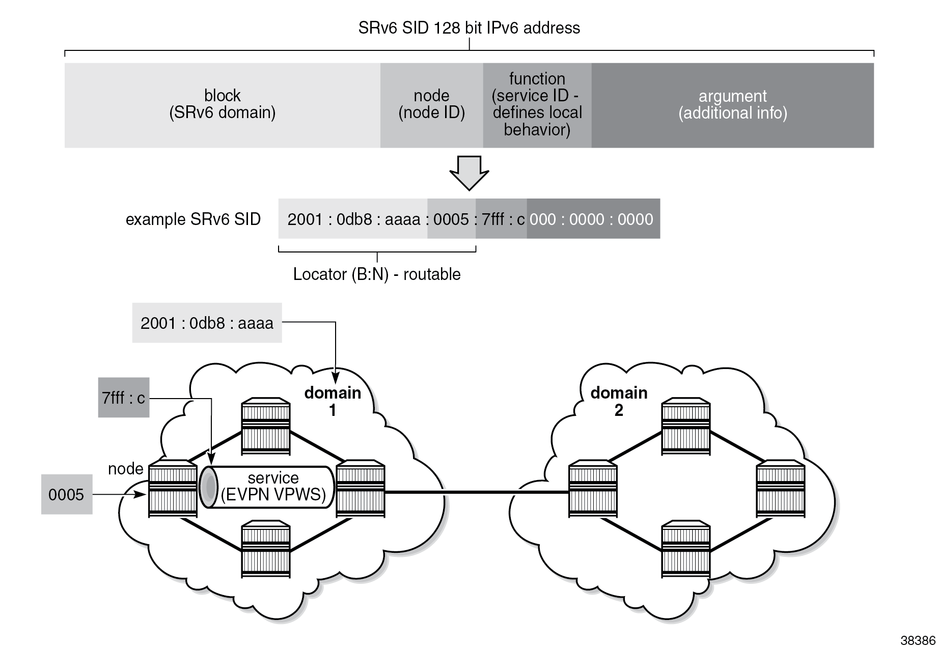
To differentiate between SIDs used in plain routing and the higher level SIDs that are used with services (such as EVPN and VPRN), the SIDs are sometimes referred to as transport SIDs and service SIDs. SIDs are advertised in routing protocols through segment routing extensions. Nokia SR OS supports such extensions in IS-IS for transport-related SIDs and in BGP for Layer 2 and Layer 3 service-related SIDs.
SIDs are an integral part of routing in SRv6, but SIDs are not interface addresses; SIDs are configured and allocated in respective segment-routing-v6 contexts (outside of the interface configuration) to the Base router and service to which they pertain.
As the figure SRv6 SID shows, the block and the node form a locator field in the SID. The locator field is used for node reachability in basic destination-based routing. Typically, a node advertises IPv6 prefixes matching the locator function of its SIDs. In SR OS, when the locator prefix is advertised in IS-IS, it is encoded in an SRv6 Locator Sub-TLV, which is an SRv6 extension in IS-IS. A node can advertise multiple locators simultaneously (for example, one locator per Flexible-Algorithm).
The block part of the locator defines an SRv6 domain. In an SRv6 domain, nodes share the same block prefix. SRv6 domains can be considered as administrative units that can be formed based on geography or some other logical entity, such as enterprise VPN. The node part of the locator is unique to each node.
The function part of the locator defines a local behavior on the node that owns the SID. Specific functions that can be associated with SIDs are described in RFC 8986 and RFC 8402. The End and End.X functions are used by IS-IS to create repair tunnels and backup paths (topology-independent loop-free-alternate (TI-LFA) and remote LFA). The combination of TI-LFA and remote LFA provides full coverage of any access network. The End function represents the node prefix which is reachable based on the shortest path. The End.X function represents links between the nodes (these links are router adjacencies which can be local or remote) and is used to specify the router adjacency (for example, for strict mode routing) out of which the frame is forwarded. Together, the End and End.X functions are used to install optimal and loop-free backup paths in the forwarding plane with achievable failover times of less than 50 ms.
The table SRv6 endpoint behaviors shows the functions used in this chapter:
| Function | Description | Advertised in |
|---|---|---|
| End | SRv6 instantiation of a node SID | IS-IS SRv6 End SID sub-TLV |
| End.X | SRv6 instantiation of an adjacency SID | IS-IS SRv6 End.X SID sub-TLV |
| End.DX2 | decapsulation and L2 cross-connect (L2VPN) | EVPN VPWS AD per-EVI route |
| End.DT4 | decapsulation and specific IPv4 table lookup (IPv4-L3VPN) | BGP |
| End.DT6 | decapsulation and specific IPv6 table lookup (IPv6-L3VPN) | BGP |
| End.B6.Encap.Red | function bound to an SRv6-policy with reduced encapsulation | N/A |
The argument field is optional, and it can carry additional information related to the local function. It is set to 0 inSR OS.
Routing
IS-IS is used as IGP to disseminate node reachability information (the node’s interface routes, BGP next hops, SRv6 locators, and node and adjacency SIDs), while BGP is used to disseminate SRv6 service SIDs and VPN and EVPN routes.
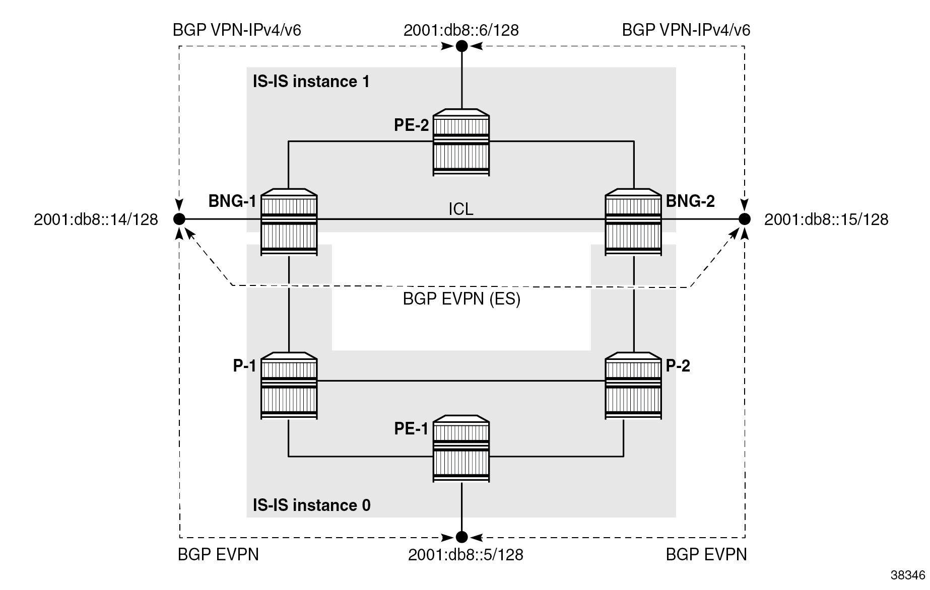
As shown in the figure Separation of routing domains, IS-IS is segmented into two instances:
- IS-IS instance 0 runs in the access network
- IS-IS instance 1 runs in the core part of the network, including the inter-chassis link (ICL) between the two BNGs
The system IPv6 addresses are included in both instances. There is no route exchange between the two IS-IS instances.
IPv6 BGP peering is established directly (with no route reflector) between the service endpoints with respective BGP address families, as shown in the figure Separation of routing domains. IPv6 BGP peering is not a prerequisite and IPv4 BGP peering would work just as well.
The ICL must be highly redundant but does not need to support high bandwidth. Its use is typically limited to subscriber synchronization and to shunt data traffic between BNGs during transient network conditions while the network reconverges during switchovers. For cost reductions, it may not be desirable to dimension this ICL to carry all subscriber traffic during prolonged periods of network failures. To minimize the use of ICL for data traffic, the topology shown in the figure Separation of routing domains relies on the separation of IS-IS routing domains between the access network and the core network, as described in the Examining failovers section. The hard separation of IS-IS routing domains is not a prerequisite or the only design option, but rather an arbitrary choice used in this chapter.
When the link between the nodes BNG-1 (with the active SRRP) and P-1 fails, the PE-1 BGP next hop becomes unreachable on BNG-1 because of the separation of IS-IS routing domains, which causes the active EVPN VPWS between BNG-1 and PE-1 to switch over to BNG-2. The switch to BNG-2, combined with SRRP-aware routing on the core side, ensures that the use of ICL is limited to transient conditions while routing is converging during the failure. The figure Optimal traffic flow during network failures shows the steady state traffic path after the network has converged: the path from PE-1 to PE-2 via P-2 and BNG-2.
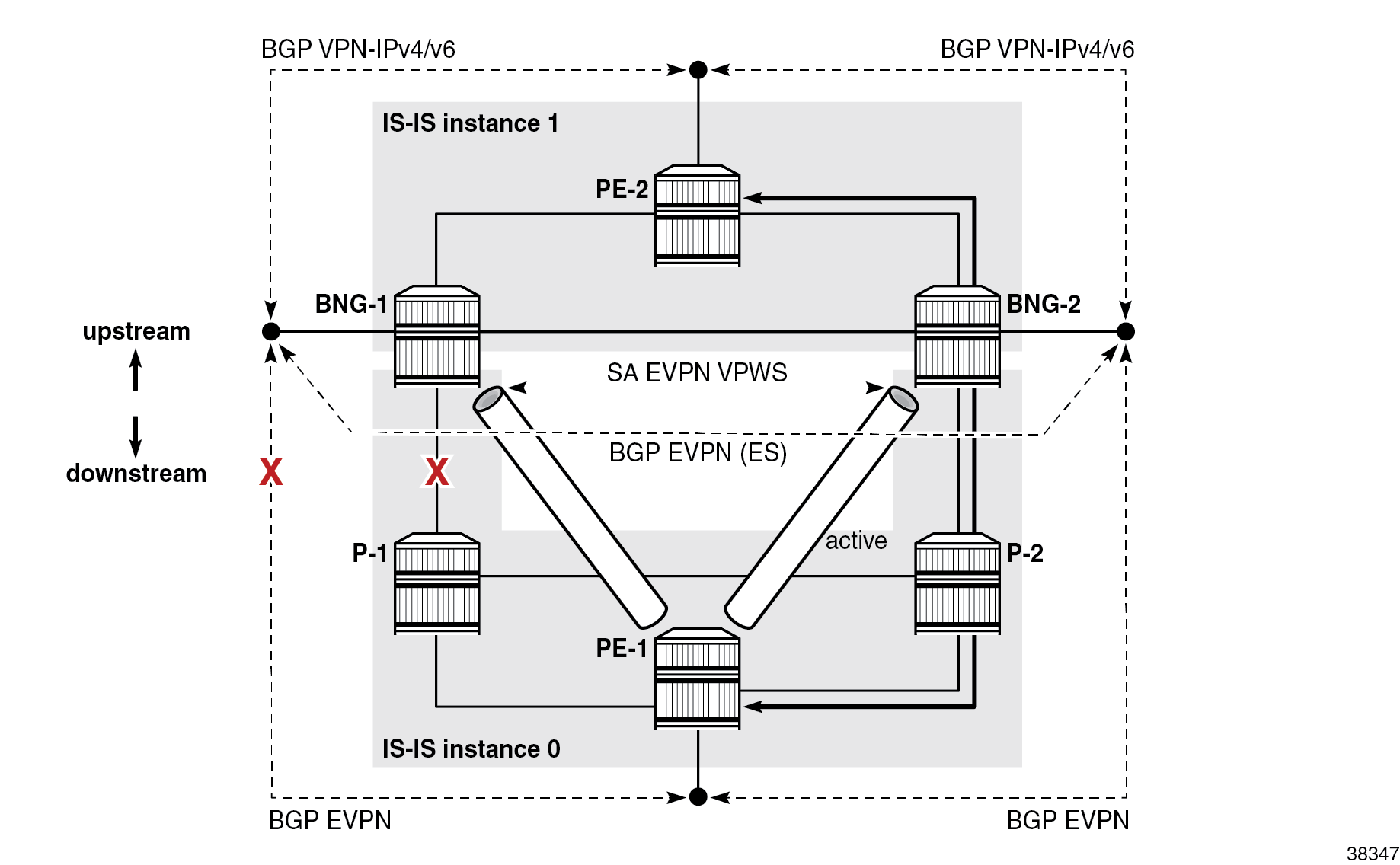
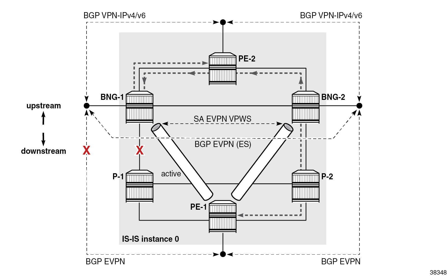
In an alternative design where all nodes are in the same IS-IS routing instance 0, the PE-1 node continues to be reachable from BNG-1 (via BNG-2 or PE-2) even after the access link on BNG-1 fails. As a result, BNG-1 remains the designated forwarder (DF) for the ES and SRRP on BNG-1 remains in the active state. This causes traffic in both directions to take a path over the ICL link or even to cross some of the core links twice, as shown in Suboptimal traffic flow during network failure . Traffic from PE-1 goes via P-2 to BNG-2, which sends the traffic to DF BNG-1 via PE-2 (the ICL is not used). BNG-1 forwards the traffic (back to) PE-2.
IPv4 addressing
Subscriber traffic in the overlay network utilizes both IPv4 and IPv6 address families, as part of dual-stack configuration. Comparatively, the underlay network is based on SRv6, with the advantage that IPv4 addressing is no longer needed.
Therefore, in the example topology, IPv4 addresses in the underlay network are removed from most interfaces. There are a few exceptions where local IPv4 addresses are kept, but without advertising them into the network, which means that routing protocols in the underlay network remain free of IPv4 addresses.
The following are exceptions where IPv4 addresses in the underlay network are still used:
- System IPv4 addresses are still used locally on each node for legacy reasons where some functionalities may still require it. For example, in EVPN VPWS multihoming, an IPv4 system address is required to derive the route distinguisher (RD) for the ES route (even if static RD for the EVPN VPWS is configured).
- Multi-chassis synchronization (MCS) peering between the two nodes is supported only over IPv4 addresses. For the MCS peering, the system IP addresses of the BNGs are used, with static routes over the IPv4 next hops configured on the direct link between the two BNG nodes. Because this link directly connects the two BNGs, no advertisement of the IPv4 prefix is required.
- The redundant-Interface command under the BNG group-interface context also requires IPv4 addressing. Those IPv4 addresses are also not advertised into the network.
SRv6 policy
For illustrative purposes, the example uses a static SR policy of type SRv6 in the access network. This SR policy is configured with segment list entries, which are node SIDs that are to be visited on the way to the final destination.
The SR policy is treated as a routing entity whose configured endpoint is installed as an entry in the tunnel table. The SR policy becomes the protocol owner of such an entry in the routing or tunnel table. The tunnel entry can be used for BGP next-hop resolution.
Configuring hops in the SR policy triggers the generation of an SRH, which is further described in the Configuration section.
The SR policy in the example steers traffic onto a longer path, despite a shorter path with lower cost being available. This behavior is shown in the figure Static SRv6 policy paths where traffic from the BNGs to PE-1, and vice versa, always flows through both P-1 and P-2.

Examining failovers
The configuration used in this chapter has been tested by running traffic and incurring network failures at various points. Traffic was monitored after the failures to ensure the traffic was flowing through a predicted path.
Traffic is run bidirectionally between two ports on a traffic generator, representing the subscribers on the 10.10.x.x networks and the Internet on the 172.16.101.x network.
BNG-1 advertises subscriber IPv4 and IPv6 subnets into the core network (VPRN) with lower cost than BNG-2, because SRRP is active on BNG-1 and standby on BNG-2.
In the access network, the ES in EVPN VPWS on BNG-1 is selected as DF due to a higher preference.
Traffic through the access network is steered by the SRH, which is inserted by the static SR policy configured on both BNGs and PE-1. In the upstream direction, traffic follows the path depicted in 8: from traffic generator port 1 via PE-1, P-2, P-1, BNG-1, and PE-2 to traffic generator port 2. Downstream traffic follows the same path in reverse direction.
Three switchovers are examined:
- switchover due to failure of the link between BNG-1 and P-1
- switchover due to failure of the network link connecting BNG-1 to PE-2
- switchover due to failure of the entire BNG-1 node
In all three cases, the failover time depends on the failure detection speed and convergence of the routing protocols. Nokia encourages operators to run performance-related tests, which includes measuring failover times, in their own test environment on service routers with Nokia native hardware (non-server based service routers).
Failure detection speed can, in some cases, be improved by bi-directional forwarding detection (BFD). In the example topology, BFD is configured for detection of BGP peer failures.
Switchover caused by the failure of the access link on BNG-1
The figure Access port failure shows a switchover scenario where the access port on BNG-1 toward P-1 is disabled and all traffic is diverted to BNG-2 as indicated. The traffic detour over the link between P-1 and P-2 is taken because the static SR policies favor longer paths over shorter.
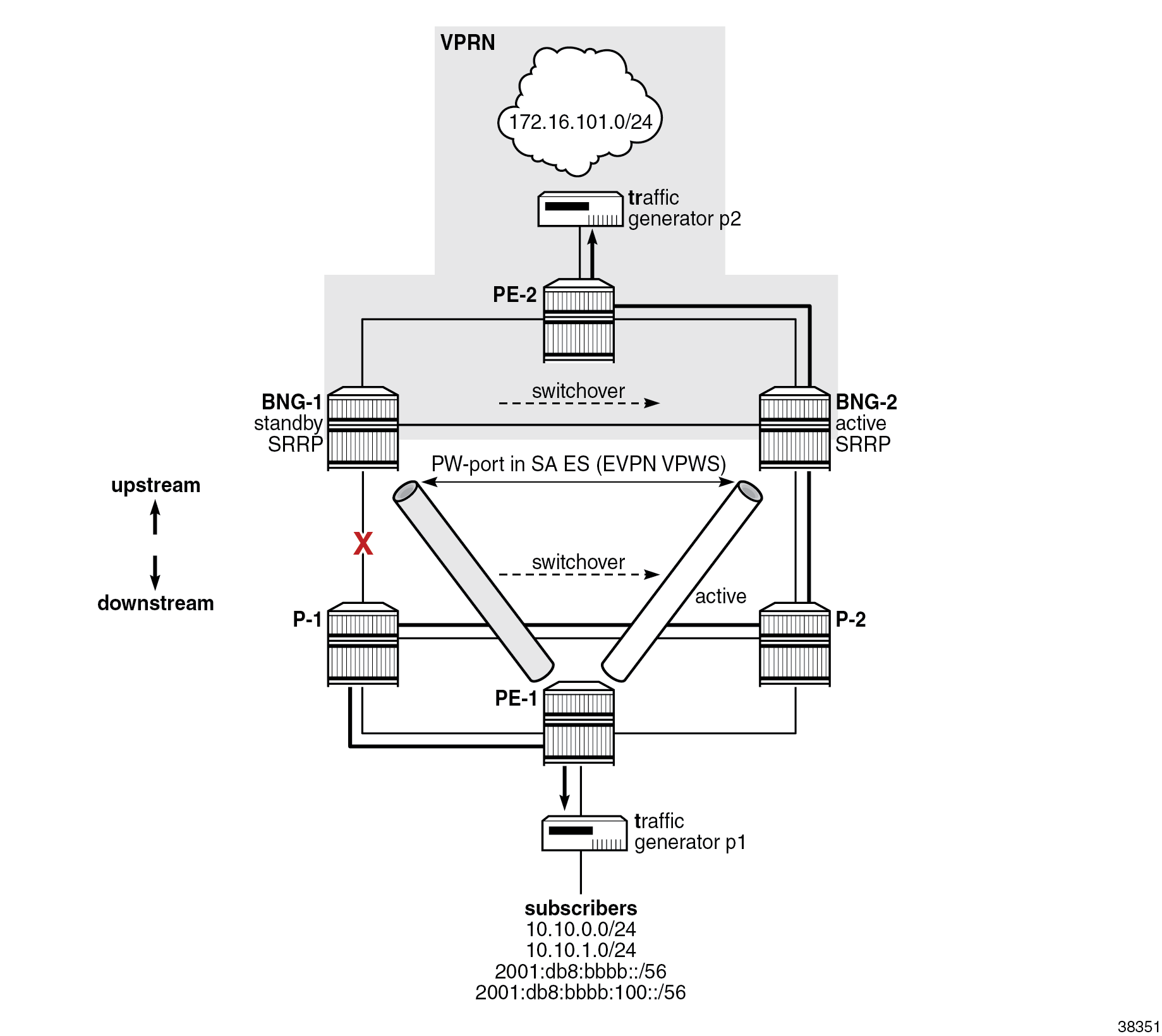
The following events trigger the traffic switchover from BNG-1 to BNG-2:
- When the access port on BNG-1 is disabled, the BGP peering connection between BNG-1 and PE-1 is lost because of the separation of IS-IS routing domains. The BGP connection is required for the advertisement of the overlay EVPN routes.
- On BNG-1, the speed of detecting the BGP connection failure is locally driven by the speeds of the link loss detection and the consequent IS-IS algorithm that is run to determine that an alternate path to the BGP peer (PE-1) does not exist.
- On PE-1, the speed of detecting the BGP connection failure is driven by the speed of IS-IS link state advertisement (LSA) propagation.
- The severed BGP connection between BNG-1 and PE-1 triggers the DF election process on the ES between the two BNGs, which is driven by BGP. BNG-2 is selected as the DF and BNG-1 as the non-DF.
- The newly elected DF on BNG-2 performs the following actions:
- It activates EVPN VPWS toward PE-1 so that traffic can be sent to it and be received from it. (More explicitly, it advertises an Auto-Discovery route with the Primary flag (P-bit) set to 1 to indicate that it is active, and the Backup flag (B-bit) set to zero.)
- It triggers activation of SRRP on BNG-2 (but does not activate it). SRRP continues to run through its own state machine, which involves waiting for three times the SRRP transmit interval (SRRP keepalive messages) before it becomes active. Due to this delay in becoming active, it is still important to have a short SRRP transmit interval configured under SRRP, even if SRRP keepalive messages are not exchanged between the two BNGs, as in this example. In other words, SRRP activation is driven by the DF outcome of the EVPN ES election process, which then triggers the SRRP activation process with its own state machine.
- PE-1 does not wait for the BGP update from BNG-2 that contains the new DF decision. PE-1 activates the stored backup route from BNG-2 as soon as it realizes, via IS-IS, that the BGP connection to BNG-1 is lost.
-
Lastly, the activation of SRRP on BNG-2 triggers the advertisement of subscriber routes into the core with a lower cost than that advertised by BNG-1. After the core network converges, traffic in the downstream direction is diverted from the link between PE-2 and BNG-1 to the link between PE-2 and BNG-2. While the routing is converging, traffic in the downstream direction might be flowing from BNG-1 to BNG-2 through the redundant interface (over the ICL) between the two BNGs.
Switchover caused by the network link failure between BNG-1 and PE-2
In the figure Network port failure, the port on BNG-1 toward PE-2 is disabled, which results in a switchover due to the network link failure between BNG-1 and PE-2. All traffic is diverted to BNG-2. The traffic detour over the link between P-1 and P-2 is taken because of the static SR policies on BNGs and PE-1.
A failure of the core link on BNG-1 diverts downstream traffic to BNG-2 in the core network, which uses VPRN. But in the access network, which uses EVPN, traffic still flows through BNG-1, which remains the DF on EVPN ES and where SRRP is active. To prevent a scenario where the inter-chassis link is used to carry traffic between the two BNGs during the failure, a feedback loop from the core port to the access port is required. In this way, the state change of the core port is reflected in the access port and, as result, traffic is completely diverted from BNG-1 to BNG-2. This feedback loop is implemented through an operational group associated with a core port and monitored by the access port.
The remainder of the switchover mechanics are the same as those in the Switchover caused by the failure of the access link on BNG-1 section.
Switchover caused by the BNG-1 node failure
After the loss of the BGP peering connection to BNG-1, BNG-2 becomes the DF for the EVPN ES. The BGP peering connection loss can be detected by a loss of link on BNG-2, by BFD, or by IS-IS LSA propagation.
BNG-2 becoming DF has the same effects as already described in the previous two cases.
Recovery
To restore the network to its state from before the failure, the operators have the option to revert traffic automatically to the primary paths that were available before the failure. The revertive behavior involves another switchover, which is associated with possible traffic loss. Whether to enable revertive behavior is a choice between the cost of another switchover measured by affected user experience due to a small traffic loss and the cost of keeping the traffic on backup paths which may not be optimized for such traffic.
To ensure minimal traffic loss when revertive behavior is enabled, the network must have fully converged after the recovery, before the switchover to the previous state occurs. For example, upon reboot, the recovered BNG must be fully integrated into the network; that is, all subscribers must be synchronized between the two BNGs, the BGP peering sessions must be reestablished, and routes exchanged. The synchronization between the BNGs is independent of the exchange of BGP routes and these events may occur in any sequence. For this reason, bootup timers must be configured properly to make sure that all relevant processes are completed before the switchover occurs. Bootup timers are described in the Configuration section.
Configuration
The complete configuration files for all six nodes in this example topology are provided in the Appendix.
The examples in this section focus on the Forwarding Path Extension (FPE)-based PW port in multihomed EVPN environments with SRv6 transport.
The configuration shown in this section is mainly for the two nodes that represent the two endpoints of the EVPN VPWS: BNG-1 and PE-1.
The configuration blocks, together with the output of the show commands, cover the following topics:
- FPE
- SRv6
- IS-IS routing related to SRv6
- BGP routing related to SRv6
- EVPN VPWS (including ES and PW port) and service-related SRv6 configuration
- VPRN-related SRv6 configuration
- multi-chassis redundancy configuration
- DHCP server configuration
- subscriber management configuration
While many of these topics are described in other chapters, the purpose of this chapter is to show how they interact together.
The less important parts in the configuration blocks or the output from the show commands are removed for brevity.
FPE
In SR OS Release 22.10, the example setup requires three FPE-based port cross-connects (PXCs) on each BNG, one for each of:
- the SRv6 origin
- the SRv6 termination
- the PW port
All three PXCs are port-based and they are set up on the same port. Selecting port-based PXCs in this example versus MAC- or internal-based PXCs is an arbitrary choice. Either type of PXC can be used.
The PXC configuration on BNG-1 is as follows. The configuration on BNG-2 is identical. Other nodes do not have a PW port and require only two PXCs for SRv6.
[pr:/configure port-xc]
A:admin@bng-1#
    pxc 1 {
        admin-state enable
        description "fpe srv6 origin"
        port-id 1/1/c4/1
    }
    pxc 2 {
        admin-state enable
        description "fpe srv6 termination"
        port-id 1/1/c4/1
    }
    pxc 3 {
        admin-state enable
        description "fpe pw-port"
        port-id 1/1/c4/1
    }
The logical PXC ports are configured as follows:
[pr:/configure]
A:admin@bng-1#
    port pxc-1.a {
        admin-state enable
    }
    port pxc-1.b {
        admin-state enable
    }
    port pxc-2.a {
        admin-state enable
    }
    port pxc-2.b {
        admin-state enable
    }
    port pxc-3.a {
        admin-state enable
    }
    port pxc-3.b {
        admin-state enable
    }
}
The following FPE configuration is required for PW port and SRv6 configuration:
[pr:/configure]
A:admin@bng-1#
    fwd-path-ext {
        sdp-id-range {
            start 17500
            end 17600
        }
        fpe 1 {
            description "srv6 origination"
            path {
                pxc 1
            }
            application {
                srv6 {
                    type origination
                }
            }
        }
        fpe 2 {
            description "srv6 termination"
            path {
                pxc 2
            }
            application {
                srv6 {
                    type termination
                }
            }
        }
        fpe 3 {
            description "pw-port on a single port"
            path {
                pxc 3
            }
            application {
                pw-port-extension { }
            }
        }
SRv6
SRv6 is configured on several levels:
- the base routing context level (which is the focus of this section)
- the IS-IS routing protocol level
- the services level
The static SRv6 policy is configured in the base routing context and is examined in the context of the Epipe to which it is applied.
Relevant to the example setup, the global SRv6 configuration under the base router provides:
- an SRv6 association with an FPE
- an SRv6 locator
- the source address
- the allocation and behavior of End and End.X SIDs
[pr:/configure router "Base" segment-routing segment-routing-v6]
A:admin@bng-1#
    origination-fpe [1]
    source-address 2001:db8::14
    locator "bng-1-loc" {
        admin-state enable
        block-length 48
        termination-fpe [2]
        prefix {
            ip-prefix 2001:db8:aaaa:14::/64
        }
    }
    base-routing-instance {
        locator "bng-1-loc" {
            function {
                end 1 {
                    srh-mode usp
                }
                end-x-auto-allocate usp protection protected { }
            }
        }
    }
The following show command displays a summary of SRv6 on a global level:
A:admin@bng-1# /show router segment-routing-v6 summary
===============================================================================
Segment Routing v6
===============================================================================
Origination FPE              : 1
Source IPv6 Address          : 2001:db8::14
===============================================================================
Locator                                                           Admin State
    Prefix
-------------------------------------------------------------------------------
bng-1-loc                                                         Up
    2001:db8:aaaa:14::/64
---snip---
The following show output lists the node and adjacency SIDs:
A:admin@bng-1# /show router segment-routing-v6 base-routing-instance
===============================================================================
Segment Routing v6 Base Routing Instance
===============================================================================
Locator
  Type       Function    SID                                     Status/InstId
    SRH-mode Protection  Interface
-------------------------------------------------------------------------------
bng-1-loc
  End                  1 2001:db8:aaaa:14:0:1000::               ok
    USP
-------------------------------------------------------------------------------
  Auto-allocated End.X: USP Protected,
-------------------------------------------------------------------------------
  End.X          *524287 2001:db8:aaaa:14:7fff:f000::            1
    USP        Protected int-1-bng-1-pe-2
    ISIS Level: L2 Mac Address: b4:a0:01:01:00:07 Nbr Sys Id: 1920.0000.2006
  End.X          *524288 2001:db8:aaaa:14:8000::                 0
    USP        Protected int-1-bng-1-p-1
    ISIS Level: L2 Mac Address: b4:9e:01:01:00:0b Nbr Sys Id: 1920.0000.2004
  End.X          *524289 2001:db8:aaaa:14:8000:1000::            1
    USP        Protected int-1-bng-1-bng-2
    ISIS Level: L2 Mac Address: b4:98:01:01:00:06 Nbr Sys Id: 1920.0000.2021
-------------------------------------------------------------------------------
Legend: * - System allocated
The InstId field for End.X SIDs shows the IS-IS instance in which they are configured.
SRv6 locators are used for node reachability and are, through route advertisements, installed in the route tables of other nodes. For example, the following output shows the SRv6 locator of BNG-1 is installed in the IPv6 routing table of BNG-2:
A:admin@bng-2# /show  router route-table ipv6

===============================================================================
IPv6 Route Table (Router: Base)
===============================================================================
Dest Prefix[Flags]                            Type    Proto     Age        Pref
      Next Hop[Interface Name]                                    Metric
-------------------------------------------------------------------------------
---snip---
2001:db8:aaaa:14::/64                         Remote  ISIS(1)   02h14m11s  18
       2001:db8:aaaa:14::/64 (tunneled:SRV6-ISIS)                   20
---snip---
IS-IS routing related to SRv6
As described in the Routing section, IS-IS is split into two instances. Instance 0, as indicated by its configured interfaces, is active on the access side. Instance 1 is active on the core side, including the link between the two BNGs.
The segment-routing-v6 section in the IS-IS configuration block references the SRv6 locator that IS-IS, together with its basic functions (node and adjacency SIDs), advertises into the network.
Some of the IS-IS configuration outside of the isis segment-routing-v6 context is directly pertinent to SRv6. For example, the SRv6 locator is only advertised when the wide-metrics command is configured.
BNG-2 is configured similarly to BNG-1. P-1, P-2, and PE-1 have only IS-IS instance 0 configured, while PE-2 has only IS-IS instance 1 configured. Although only a portion of the configuration on BNG-1 is provided, the IS-IS configuration on other nodes in respective IS-IS instances is similar with different naming for interfaces and for the SRv6 locator.
Between the two IS-IS instances in BNG-1, the only configuration difference is that they reference different interfaces. In the following example, only one repeated part of the IS-IS instance 1 configuration is shown:
[pr:/configure router "Base"]
    isis 0 {
        admin-state enable
        advertise-passive-only false
        advertise-router-capability area
        ipv6-routing native
        level-capability 2
        traffic-engineering true
        area-address [49.0001]
        loopfree-alternate {
            remote-lfa {
            }
            ti-lfa {
            }
        }
        traffic-engineering-options {
            ipv6 true
            application-link-attributes {
            }
        }
        segment-routing-v6 {
            admin-state enable
            locator "bng-2-loc" {
                level-capability 2
                level 2 {
                    metric 10
                }
            }
        }
        interface "int-1-bng-2-p-2" {
        }
        interface "system" {
        }
        level 2 {
            wide-metrics-only true
        }
    }
    isis 1 {
        ---snip---
        interface "int-1-bng-2-bng-1" {
        }
        interface "int-1-bng-2-pe-2" {
        }
        interface "system" {
        }
        ---snip---
The following show command confirms that IS-IS adjacencies in instance 1 are up. A similar command can be used for IS-IS instance 0.
A:admin@bng-1# /show  router isis 1 adjacency

===============================================================================
Rtr Base ISIS Instance 1 Adjacency
===============================================================================
System ID                Usage State Hold Interface                     MT-ID
-------------------------------------------------------------------------------
bng-2                    L2    Up    24   int-1-bng-1-bng-2             0
pe-2                     L2    Up    9    int-1-bng-1-pe-2              0
-------------------------------------------------------------------------------
Adjacencies : 2
Further SRv6-related information in IS-IS, such as exchanged locators or node SIDs, can be explored by using commands under the following hierarchy:
A:admin@bng-1# /show router isis 1 segment-routing-v6
The following show command lists the locators that are present in IS-IS instance 1 on BNG-1. These locators can be local or learned through IS-IS. For BNG-1, locator 2001:db8:aaaa:14::/64 is local.
A:admin@bng-1# /show  router isis 1 segment-routing-v6 locator

===============================================================================
Rtr Base ISIS Instance 1 SRv6 Locator Table
===============================================================================
Prefix                             AdvRtr                        MT     Lvl/Typ
 AttributeFlags                     Tag                           Flags  Algo
-------------------------------------------------------------------------------
2001:db8:aaaa:6::/64               pe-2                          0      2/Int.
  -                                  0                             -      0
2001:db8:aaaa:14::/64              bng-1                         0      2/Int.
  -                                  0                             -      0
2001:db8:aaaa:15::/64              bng-2                         0      2/Int.
  -                                  0                             -      0
-------------------------------------------------------------------------------
BGP peering
IBGP is used to exchange EVPN and VPRN routes between the BNGs and the edge nodes (PE-1 and PE-2). IBGP peering sessions with corresponding address families are shown in the figure Separation of routing domains.
In the EVPN part of the network, BGP is used between the two BNGs to elect the DF on the ES, and between the BNGs and PE-1 to exchange the reachability EVPN routes. PE-1 uses the advertised EVPN route from the BNGs to set up and activate an EVPN VPWS connection toward the active (DF) BNG.
In the VPRN, the two BNGs exchange VPN-IPv4 and VPN-IPv6 routes (subscriber and Internet routes from the traffic generator) with PE-2.
BGP is not configured on nodes P-1 and P-2.
Consider the following when configuring BGP:
- All BGP peers are IPv6 peers.
- The advertise-ipv6-next-hops command for the VPN IPv4 and VPN IPv6 address families must be explicitly enabled. By default, only IPv4 next hops are advertised, which in this case do not exist. The counterpart command for EVPN address family is enabled under the bgp-evpn configuration for the corresponding Epipe: the route-next-hop system-ipv6 command is configured in the configure service epipe <..> bgp-evpn segment-routing-v6 context.
- The extended-nh-encoding command must be enabled to allow IPv6 next hops for the VPN IPv4 address family.
- The SR policy used for traffic steering is deployed in the access network.
- BFD is enabled for faster failure detection of all BGP neighbors.
For the SR policy to take effect, the target node referenced in the endpoint command must advertise its routes with a color extended community, in the format community:color, that matches the one configured in the policy. The configured color extended community advertised by BNG-1 is color-20. Rather than exporting this color extended community through a VSI-export policy at the service level, for simplicity reasons, it is exported at the global BGP level. This way, the color extended community can be easily added to the existing communities, such as the route target (RT) community in the Epipe.
The routing policy name used to export the color extended community is "pol-color-20". It is applied only toward the BGP peer PE-1 (neighbor 2001:db8::5). To activate the export policy, the vpn-apply-export command must be specifically enabled in MD-CLI.
The BGP configuration on BNG-1 is as follows:
[pr:/configure router "Base"]
A:admin@bng-1#
    bgp {
        admin-state enable
        vpn-apply-export true
        vpn-apply-import true
        rapid-withdrawal true
        rapid-update {
            vpn-ipv4 true
            vpn-ipv6 true
            evpn true
        }
        extended-nh-encoding {
            vpn-ipv4 true
        }
        advertise-ipv6-next-hops {
            vpn-ipv6 true
            vpn-ipv4 true
        }
        group "evpn" {
            peer-as 64500
            local-address 2001:db8::14
            bfd-liveness true
            family {
                evpn true
            }
        }
        group "ipvpn" {
            peer-as 64500
            local-address 2001:db8::14
            bfd-liveness true
            family {
                vpn-ipv4 true
                vpn-ipv6 true
            }
        }
        neighbor "2001:db8::5" {
            group "evpn"
            export {
                policy ["pol-color-20"]
            }
        }
        neighbor "2001:db8::6" {
            group "ipvpn"
        }
        neighbor "2001:db8::15" {
            group "evpn"
        }
    }
The following shows the export policy "pol-color-20", which adds the community "color-20" to all BGP route advertisements with the family type EVPN originating from the service with the tag 11. For this purpose, the EVPN VPWS (Epipe) is explicitly tagged with tag 11, as shown in the Epipe configuration section.
[pr:/configure policy-options]
A:admin@bng-1#
    community "color-20" {
        member "color:00:20" { }
    }
    policy-statement "pol-color-20" {
            entry 10 {
            from {
                family [evpn]
                tag 11
            }
            action {
                action-type accept
                community {
                    add ["color-20"]
                }
            }
        }
    }
BFD is enabled on the interface advertised as the next hop in BGP updates:
[pr:/configure router "Base"]
A:admin@bng-1#
    autonomous-system 64500
    router-id 192.0.2.20
    interface "system" {
        ipv4 {
            primary {
                address 192.0.2.20
                prefix-length 32
            }
        }
        ipv6 {
            bfd {
                admin-state enable
                transmit-interval 100
                receive 100
                multiplier 2
            }
            address 2001:db8::14 {
                prefix-length 128
            }
        }
    }
The BGP configurations on nodes BNG-2, PE-1, and PE-2 are similar in that both PE-1 and PE-2 nodes only interact with the two BNGs within their respective address families.
The following command shows a summary of the BGP status. The output of this command has been shortened to show only that the peers are communicating and exchanging routes. The advertised routes are examined in the service configuration sections.
A:admin@bng-1# show router bgp summary
===============================================================================
 BGP Router ID:192.0.2.20       AS:64500       Local AS:64500
===============================================================================
BGP Admin State         : Up          BGP Oper State              : Up
---snip---
===============================================================================
Neighbor
Description
                   AS PktRcvd InQ  Up/Down   State|Rcv/Act/Sent (Addr Family)
                      PktSent OutQ
-------------------------------------------------------------------------------
2001:db8::5
                64500   11617    0 04d00h46m 1/1/3 (Evpn)
                        11621    0
2001:db8::6
                64500   11618    0 04d00h46m 1/1/2 (VpnIPv4)
                        11620    0           1/1/2 (VpnIPv6)
2001:db8::15
                64500   11621    0 04d00h46m 3/3/3 (Evpn)
                        11620    0
-------------------------------------------------------------------------------
EVPN VPWS (including ES and PW port) and related SRv6 configuration
EVPN VPWS is configured as an Epipe. The three instances to be configured are:
- SRv6
- BGP
- BGP-EVPN
The SRv6 instance is configured at the top level of the Epipe and represents the dataplane instantiation of SRv6. In Release 22.10, SRv6 can be used only with the EVPN control plane (BGP-EVPN). Under this hierarchy:
- The SRv6 locator is referenced.
- The function part (End.DX2) required for creating the service SID is defined. The function value can be allocated statically or automatically; in this case, it is allocated automatically.
The BGP instance is configured at the top level of the Epipe (bgp 1 in the example), where RT and RD can be optionally configured (otherwise they are auto-derived) and where VSI policies are applied.
The BGP-EVPN instance is configured at the top level of the Epipe, with information related to EVPN control plane signaling. The number 1 in the segment-routing-v6 1 configuration under the bgp-evpn context refers to the bgp 1 instance. Consider the following aspects of this configuration:
- The source IPv6 address of the SRv6 tunnel is, in this case, the system IP address (2001:db8::14). If the source address is not defined in the configuration, the one from the global SRv6 configuration is used. Without the source address defined in one of those two places, the SRv6 transport for the service is non-operational.
- The Epipe is tagged with a tag 11 (0xb), which is used to identify the Epipe in the BGP export policy for the color extended community, as described in the BGP peering section.
- The resolution fallback-tunnel-to-route-table command forces the system to first check if the next hops for the received EVPN routes are present (or resolved) in the tunnel table, before falling back to the routing table for the resolution. This is required because the endpoint in the SR policy, along with the color, is installed in the tunnel table. A valid next-hop resolution via SR policy is a trigger for the addition of the SRH to the packet header. Without the SR policy, the SRH is not added, and the packet takes the shortest path to the final destination based on plain destination-based routing.
- The route-next-hop command identifies the next hop that is used in EVPN route advertisements. In this case, it is the system IPv6 address, but it can be any reachable locally configured IPv6 address.
The benefit of using the multi-instance provisioning model via three provisioning instances (SRv6, BGP, and BGP-EVPN) within the Epipe is that it offers more configuration flexibility when it comes to provisioning multiple data and control planes in the same service.
The Epipes on the two BNGs are configured with the same Ethernet tags. When the AD per-EVI routes with those tags are advertised, the AD per-EVI route advertised from BNG-1 has the P-bit set to 1 and the B-bit set to 0, making it the active route on PE-1. BNG-2 advertises the same AD per-EVI route (but with a different next-hop) with the value of the P-bit set to 0 and the B-bit to 1, making it the standby route on the PE-1.
[pr:/configure service epipe "evpn-dual-homing"]
A:admin@bng-1#
    admin-state enable
    service-id 11
    customer "1"
    segment-routing-v6 1 {
        locator "bng-1-loc" {
            function {
                end-dx2 {
                }
            }
        }
    }
    bgp 1 {
    }
    bgp-evpn {
        evi 11
        local-attachment-circuit "bng" {
            eth-tag 2
        }
        remote-attachment-circuit "access" {
            eth-tag 1
        }
        segment-routing-v6 1 {
            admin-state enable
            default-route-tag 0xb
            source-address 2001:db8::14
            resolution fallback-tunnel-to-route-table
            srv6 {
                instance 1
                default-locator "bng-1-loc"
            }
            route-next-hop {
                system-ipv6
            }
        }
    }
The preceding configuration defines the remote EVPN destination (or connection to the remote node over SRv6) in the Epipe. The local termination point in the Epipe is a PW port. The PW port is FPE-based and associated with the Epipe, as follows:
[pr:/configure pw-port 1]
A:admin@bng-1#
    encap-type qinq
    epipe "evpn-dual-homing" {
        admin-state enable
        fpe-id 3
        oper-up-on-mh-standby true
    }
The oper-up-on-mh-standby command is related to an optimization of the ES in EVPN VPWS multihoming. The effect of this command is that the PW port and its SAPs remain operationally up when the associated ES is non-DF. This effect results in faster recovery during switchovers when the PW port has a large number of PW SAPs in the subscriber-management environment. In other words, during a non-DF to DF transition (standby to active), the system does not have to wait additional time to bring up thousands of PW SAPs from a down to an up state before it starts forwarding traffic.
The geo-redundant BNG setup in this chapter relies on two superimposed redundancy mechanisms:
- EVPN multihoming deployed in the access network-based DF election on the ES
- SRRP-based redundancy in ESM
These two redundancy mechanisms are, by themselves, independent of each other. However, to provide predictable results, they must be made co-dependent where one mechanism drives the other. In this context, EVPN MH as a technology deployed in the access network is used to detect the failures and to drive the state of SRRP. SRRP follows the states of the EVPN MH through operational groups.
ESM geo-redundancy based on SRRP does not support active-active mode of operation for a set of paired SRRP instances. As a result, the EVPN MH must be configured in the single-active (SA) mode of operation. The load-balancing between the two BNGs is achieved by distributing the activity of multiple SRRP instances across the two BNGs, some of them being active on one side and some of them on the other. In other words, the granularity of load balancing in ESM is per SRRP instance.
The configuration for coupling EVPN MH and SRRP through operational groups is shown in the following three configuration snippets, involving the definition of the operational group, the SA ES, and the SRRP messaging SAP.
The following configures the operational group "ES-1" with hold times of 0 s to prevent any reaction time delays during switchovers. Only the up time is set explicitly to 0 (from a default value of 4 s). The default value for a hold down time is already set to 0.
[pr:/configure service oper-group "ES-1"]
A:admin@bng-1#
    hold-time {
        up 0
    }
The following configures SA ES "ES-1" as part of the operational group "ES-1" and associated with PW-port 1. The state of the operational group "ES-1" depends on the state of the ES. If the ES is elected as the DF, then the operational group is up. Otherwise, it is down.
[pr:/configure service system]
A:admin@bng-1#
    bgp {
        evpn {
            ethernet-segment "ES-1" {
                admin-state enable
                esi 0x01010101010101010101
                orig-ip 2001:db8::14
                route-next-hop 2001:db8::14
                multi-homing-mode single-active
                oper-group "ES-1"
                df-election {
                    es-activation-timer 0
                    service-carving-mode manual
                    manual {
                        preference {
                            mode revertive
                            value 150
                        }
                    }
                }
                association {
                    pw-port 1 {
                        pw-port-headend true
                    }
                }
            }
        }
    }
In the preceding ES configuration, the orig-ip command and the route-next-hop command must be explicitly configured in pure IPv6 environments. By default, the ES route is advertised with an IPv4 address as the next hop, which is not reachable in this example.
Under the df-election context, the configuration of the preference value influences which side becomes active and which becomes standby and the configuration of the preference mode indicates whether to enable revertive behavior, as explained in the Recovery section. In this example, the es-activation-timer command is set to 0 s, which means that the DF election occurs immediately after the failure is detected. Configuring this timer to a value greater than 0 allows some time for the peer routes to be received and collected before DF election is run. This configuration is applicable to environments with multiple routes and nodes in the same ES, but can be ignored in this example topology with only two BNGs.
The following configures the SRRP messaging SAP that tracks the state of the ES (active/standby) by monitoring the operational group "ES-1". The state of the SRRP messaging SAP is up if the ES is a DF, and down if it is a non-DF. An SRRP instance with a messaging SAP in a down state assumes the INIT state, rendering its side as standby. The pairing SRRP instance on the other BNG becomes active.
[pr:/configure service vprn "dual-homing" subscriber-interface "sub-int-1" group-interface "group-int-1"]
A:admin@bng-1#
    srrp 1 {
        admin-state enable
        keep-alive-interval 2
        message-path pw-1:2.4094
    }
    sap pw-1:2.4094 {
        monitor-oper-group "ES-1"
    }
The boot timer, whose purpose is to wait for routing to converge after a node reboots, is also important when revertive mode is enabled in the ES. The boot timer accounts for completion of subscriber synchronization between the two BNGs upon reboot. In this example, there is a wait time of 2 minutes after the node reboot for the network to converge before the ES is considered stable and ready for DF election.
*[pr:/configure redundancy]
A:admin@bng-1#
    bgp-evpn {
        ethernet-segment {
            boot-timer 120
        }
    }
The multihomed Epipe configuration on PE-1 (the subscriber-connecting access node) is as follows:
[pr:/configure service epipe "dual-homing"]
A:admin@pe-1# info
    admin-state enable
    service-id 11
    customer "1"
    segment-routing-v6 1 {
        locator "pe-1-loc" {
            function {
                end-dx2 {
                }
            }
        }
    }
    sap 1/1/c3/1:*.* {
    }
    bgp-evpn {
        evi 11
        local-attachment-circuit "access" {
            eth-tag 1
        }
        remote-attachment-circuit "bng" {
            eth-tag 2
        }
        segment-routing-v6 1 {
            admin-state enable
            default-route-tag 0xb
            source-address 2001:db8::5
            resolution fallback-tunnel-to-route-table
            srv6 {
                instance 1
                default-locator "pe-1-loc"
            }
            route-next-hop {
                system-ipv6
            }
        }
    }
SR policy
An SR policy is identified by the tuple <headend, color,
endpoint>, and its origin can be derived from the path computation
element protocol (PCEP), BGP, or may be static via configuration.
In this example, a static SR policy is used in the access network as a traffic-engineering tool to guide traffic through a predetermined network path. This path is configured in the SR policy segment-list command as a list of next hop SIDs that are programmed into the SRH.
The SR policy is not explicitly applied to an object in a classical sense, such
as routing policies, which are applied in routing and service contexts. Instead,
the end-node and the color parameters
configured in the SR policy are programmed (or activated) in the tunnel table.
As such, the SR policy is used for the BNG advertised next-hop resolution in the
tunnel table. Forcing the next-hop resolution through the tunnel-table is
configured via the resolution route-table | tunnel-table |
fallback-tunnel-to-route-table command under the Epipe
configuration.
The segment-list command references the node-SIDs, while the
endpoint configured in the SR policy is not a SID but
instead a regular IPv6 address of the destination node. When multiple routing
policies with the same endpoint and color are defined, the one with the highest
preference prevails and is installed in the tunnel-table.
The head-end local command signifies that the SR policy is locally defined and activated, as opposed to advertised to BGP peers.
The binding SID is a mandatory local SID associated with the SR policy. Its
function value is end-b6-encaps-red.
The reachability of the first SID in the SR policy must be validated before the SR policy is activated.
Multiple segment lists can be defined in the SR policy. Traffic between these segment lists can be distributed according to the configured weight (not shown in the following configuration).
The SR policy does not have the configuration option for the source-address. Instead, it uses the one configured for the segment-routing configuration in the global routing context. Without the source-address configured in the global SRv6 context, the SR policy is not activated.
[pr:/configure router "Base" segment-routing sr-policies]
A:admin@bng-1#
    admin-state enable
    static-policy "to-pe-1-long-path" {
        admin-state enable
        color 20
        endpoint 2001:db8::5
        preference 150
        head-end local
        type srv6
        segment-routing-v6 {
            binding-sid 1 {
                locator {
                    locator-name "bng-1-loc"
                    function end-b6-encaps-red
                }
            }
        }
        segment-list 1 {
            admin-state enable
            segment 1 {
                srv6-sid 2001:db8:aaaa:4:0:1000::
            }
            segment 2 {
                srv6-sid 2001:db8:aaaa:a:0:1000::
            }
        }
    }
To verify that the SR policy has been activated:
A:admin@pe-1# show router segment-routing sr-policies static

===============================================================================
SR-Policies Path
===============================================================================
-------------------------------------------------------------------------------
Type            : srv6
Active          : Yes                   Owner           : static
Color           : 20
Head            : 0.0.0.0               Endpoint Addr   : 2001:db8::14
RD              : 0                     Preference      : 150
SRv6 BSID 1     : 2001:db8:aaaa:5:0:7000::
TunnelId        : 917506                Age             : 189018
Origin ASN      : 0                     Origin          : 0.0.0.0
NumReEval       : 1                     ReEvalReason    : route-add
NumActPathChange: 0                     Last Change     : 11/01/2022 08:39:33
Maintenance Policy: N/A

Path Segment Lists:
Segment-List    : 1                     Weight          : 1
S-BFD State     : Down                  S-BFD Transitio*: 0
Num Segments    : 2                     Last Change     : 11/01/2022 08:39:30
  Seg 1 SID   : 2001:db8:aaaa:a:0:1000::                 State : resolved-up
  Seg 2 SID   : 2001:db8:aaaa:4:0:1000::                 State : N/A

-------------------------------------------------------------------------------
Type            : srv6
Active          : Yes                   Owner           : static
Color           : 30
Head            : 0.0.0.0               Endpoint Addr   : 2001:db8::15
RD              : 0                     Preference      : 150
SRv6 BSID 1     : 2001:db8:aaaa:5:0:6000::
TunnelId        : 917507                Age             : 189036
Origin ASN      : 0                     Origin          : 0.0.0.0
NumReEval       : 1                     ReEvalReason    : route-add
NumActPathChange: 0                     Last Change     : 11/01/2022 08:39:33
Maintenance Policy: N/A

Path Segment Lists:
Segment-List    : 1                     Weight          : 1
S-BFD State     : Down                  S-BFD Transitio*: 0
Num Segments    : 2                     Last Change     : 11/01/2022 08:39:30
  Seg 1 SID   : 2001:db8:aaaa:4:0:1000::                 State : resolved-up
  Seg 2 SID   : 2001:db8:aaaa:a:0:1000::                 State : N/A
Verify routes
In this section, show commands are used to verify forwarding and show routing-related information. The outputs from the following show commands focus primarily (but not exclusively) on nodes BNG-1 and PE-1, which are the endpoints of the active leg of EVPN VPWS multihoming.
The following command shows the SRv6 information on BNG-1. The locator SID is advertised to other nodes via IS-IS. The locator SID is installed in the routing table of all other nodes and is used for reachability information.
A:admin@bng-1# show router segment-routing-v6 locator
=============================================================================
Locator bng-1-loc
=============================================================================
Admin State                  : Up
Prefix                       : 2001:db8:aaaa:14::/64
Block Length                 : 48
Label Block                  :
Function Length              : 20
Flex Algorithm               : 0
Termination FPE              : 2
Static Function
  Max Entries                : 1
  Label-Block                :
---snip---
The following command lists different SIDs allocated to BNG-1:
- one node SID (End), advertised in IS-IS
- three adjacency SIDs (End.X), representing the BNG-1 connections to adjacent nodes BNG-2, PE-2, and P-1 (these SIDs are used to build fast failover alternate paths and are also advertised in IS-IS)
- one EVPN SID (End.DX2), advertised via BGP-EVPN for EVPN routes
- two VPN SIDs (End.DT4 and End.DT6), advertised via BGP-IPVPN for VPN-IPv4 and VPN-IPv6 routes
- one binding SID (End.b6.encaps.red), for the SRv6 static segment-policy (this SID is not advertised in this case)
A:admin@bng-1# show router segment-routing-v6 local-sid

===============================================================================
Segment Routing v6 Local SIDs
===============================================================================
SID                                               Type           Function
  Locator
  Context
-------------------------------------------------------------------------------
2001:db8:aaaa:14:0:1000::                         End            1
  bng-1-loc
  Base
2001:db8:aaaa:14:0:2000::                         End.b6.encaps* 2
  bng-1-loc
  None
2001:db8:aaaa:14:7fff:c000::                      End.DT6        524284
  bng-1-loc
  SvcId: 10 Name: dual-homing
2001:db8:aaaa:14:7fff:d000::                      End.DT4        524285
  bng-1-loc
  SvcId: 10 Name: dual-homing
2001:db8:aaaa:14:7fff:e000::                      End.DX2        524286
  bng-1-loc
  SvcId: 11 Name: evpn-dual-homing
2001:db8:aaaa:14:7fff:f000::                      End.X          524287
  bng-1-loc
  None
2001:db8:aaaa:14:8000::                           End.X          524288
  bng-1-loc
  None
2001:db8:aaaa:14:8000:1000::                      End.X          524289
  bng-1-loc
  None
The following route table on BNG-1 shows:
- system IPv6 interfaces from all other nodes learned through IS-IS
- IPv6 prefixes on links between all nodes learned through IS-IS
- SRv6 locators from all nodes learned through IS-IS
- all local SIDs except for service SIDs, which are part of services and not global routing
BNGs are connected to both the core network (VPRN) and the access network (EVPN), so network addresses from all nodes are visible on a BNG. By contrast, the PE-1 node in the EVPN part of the network sees only routes in the EVPN part of the network, but not the routes in the VPRN part of the network (Example topology).
A:admin@bng-1# show router route-table ipv6

===============================================================================
IPv6 Route Table (Router: Base)
===============================================================================
Dest Prefix[Flags]                            Type    Proto     Age        Pref
      Next Hop[Interface Name]                                    Metric
-------------------------------------------------------------------------------
2001:db8::4/128                               Remote  ISIS      02d03h06m  18
       fe80::b69e:ffff:fe00:0-"int-1-bng-1-p-1"                     10
2001:db8::5/128                               Remote  ISIS      02d03h06m  18
       fe80::b69e:ffff:fe00:0-"int-1-bng-1-p-1"                     20
2001:db8::6/128 [L]                           Remote  ISIS(1)   02d03h06m  18
       fe80::b6a0:ffff:fe00:0-"int-1-bng-1-pe-2"                    10
2001:db8::a/128                               Remote  ISIS      02d03h06m  18
       fe80::b69e:ffff:fe00:0-"int-1-bng-1-p-1"                     20
2001:db8::14/128                              Local   Local     02d03h06m  0
       system                                                       0
2001:db8::15/128 [L]                          Remote  ISIS(1)   02d03h06m  18
       fe80::b697:ffff:fe00:0-"int-1-bng-1-bng-2"                   10
2001:db8::100/120                             Remote  ISIS      02d03h06m  18
       fe80::b69e:ffff:fe00:0-"int-1-bng-1-p-1"                     20
2001:db8::200/120                             Remote  ISIS      02d03h06m  18
       fe80::b69e:ffff:fe00:0-"int-1-bng-1-p-1"                     30
2001:db8::300/120                             Remote  ISIS      02d03h06m  18
       fe80::b69e:ffff:fe00:0-"int-1-bng-1-p-1"                     20
2001:db8::400/120                             Remote  ISIS      02d03h06m  18
       fe80::b69e:ffff:fe00:0-"int-1-bng-1-p-1"                     30
2001:db8::500/120                             Local   Local     02d03h06m  0
       int-1-bng-1-p-1                                              0
2001:db8::600/120                             Remote  ISIS      02d03h06m  18
       fe80::b69e:ffff:fe00:0-"int-1-bng-1-p-1"                     30
2001:db8::700/120                             Local   Local     02d03h06m  0
       int-1-bng-1-bng-2                                            0
2001:db8::800/120                             Local   Local     02d03h06m  0
       int-1-bng-1-pe-2                                             0
2001:db8::900/120 [L]                         Remote  ISIS(1)   02d03h06m  18
       fe80::b6a0:ffff:fe00:0-"int-1-bng-1-pe-2"                    20
2001:db8::a00/120                             Remote  ISIS      02d03h06m  18
       fe80::b69e:ffff:fe00:0-"int-1-bng-1-p-1"                     20
2001:db8::6400/120                            Remote  ISIS      02d03h06m  18
       fe80::b69e:ffff:fe00:0-"int-1-bng-1-p-1"                     30
2001:db8::6500/120 [L]                        Remote  ISIS(1)   02d03h06m  18
       fe80::b6a0:ffff:fe00:0-"int-1-bng-1-pe-2"                    20
2001:db8:aaaa:4::/64                          Remote  ISIS      02d03h06m  18
       2001:db8:aaaa:4::/64 (tunneled:SRV6-ISIS)                    20
2001:db8:aaaa:5::/64                          Remote  ISIS      02d03h06m  18
       2001:db8:aaaa:5::/64 (tunneled:SRV6-ISIS)                    30
2001:db8:aaaa:6::/64                          Remote  ISIS(1)   02d03h06m  18
       2001:db8:aaaa:6::/64 (tunneled:SRV6-ISIS)                    20
2001:db8:aaaa:a::/64                          Remote  ISIS      02d03h06m  18
       2001:db8:aaaa:a::/64 (tunneled:SRV6-ISIS)                    30
2001:db8:aaaa:14::/64                         Local   SRV6      02d03h06m  3
       fe80::201-"_tmnx_fpe_2.a"                                    0
2001:db8:aaaa:14:0:1000::/128                 Local   SRV6      02d03h06m  3
       Black Hole                                                   0
2001:db8:aaaa:14:0:2000::/128                 Local   SRV6-Pol* 02d03h06m  14
       2001:db8::5 (tunneled:SRV6-Policy:917506)                    1
2001:db8:aaaa:14:7fff:f000::/128              Local   ISIS(1)   02d03h06m  18
       2001:db8:aaaa:14:7fff:f000:: (tunneled:SRV6-ISIS)            10
2001:db8:aaaa:14:8000::/128                   Local   ISIS      02d03h06m  18
       2001:db8:aaaa:14:8000:: (tunneled:SRV6-ISIS)                 10
2001:db8:aaaa:14:8000:1000::/128              Local   ISIS(1)   02d03h06m  18
       2001:db8:aaaa:14:8000:1000:: (tunneled:SRV6-ISIS)            10
2001:db8:aaaa:15::/64                         Remote  ISIS(1)   02d03h06m  18
       2001:db8:aaaa:15::/64 (tunneled:SRV6-ISIS)                   20
The state of the ES "ES-1" on the two BNGs is DF for BNG-1 and NDF for BNG-2, as follows:
A:admin@bng-1# /show  service  id "evpn-dual-homing" ethernet-segment "ES-1"
---snip---
Pw-Port               Eth-Seg                          Status
-----------------------------------------------------------------------------
1                     ES-1                             DF


A:admin@bng-2# /show  service  id "evpn-dual-homing" ethernet-segment "ES-1"
---snip---
Pw-Port               Eth-Seg                          Status
-----------------------------------------------------------------------------
1                     ES-1                             NDF
PE-1 receives the following two AD per-EVI EVPN routes: the first AD per-EVI route is received from BNG-1 as primary (P=1, B=0), while the second AD per-EVI route is received from BNG-2 as backup (P=0, B=1):
A:admin@pe-1# show router  bgp routes evpn auto-disc tag 2 hunt
===============================================================================
 BGP Router ID:192.0.2.5        AS:64500       Local AS:64500
===============================================================================
 Legend -
 Status codes  : u - used, s - suppressed, h - history, d - decayed, * - valid
                 l - leaked, x - stale, > - best, b - backup, p - purge
 Origin codes  : i - IGP, e - EGP, ? - incomplete

===============================================================================
BGP EVPN Auto-Disc Routes
===============================================================================
-------------------------------------------------------------------------------
RIB In Entries
-------------------------------------------------------------------------------
Nexthop        : 2001:db8::14
From           : 2001:db8::14
Res. Nexthop   : fe80::b69e:ffff:fe00:0
Local Pref.    : 100                    Interface Name : int-1-pe-1-p-1
AIGP Metric    : None                   IGP Cost       : 30
Community      : color:00:20 target:64500:11
                 l2-attribute:MTU: 1514 C: 0 P: 1 B: 0
Originator Id  : None                   Peer Router Id : 192.0.2.20
Flags          : Used Valid Best IGP
Route Source   : Internal
EVPN type      : AUTO-DISC
ESI            : 01:01:01:01:01:01:01:01:01:01
Tag            : 2
Route Dist.    : 192.0.2.20:11
MPLS Label     : 524286
Route Tag      : 0
Last Modified  : 02d03h38m
SRv6 TLV Type  : SRv6 L2 Service TLV (6)
SRv6 SubTLV    : SRv6 SID Information (1)
Sid            : 2001:db8:aaaa:14::
Full Sid       : 2001:db8:aaaa:14:7fff:e000::
Behavior       : End.DX2 (21)
SRv6 SubSubTLV : SRv6 SID Structure (1)
Loc-Block-Len  : 48                     Loc-Node-Len   : 16
Func-Len       : 20                     Arg-Len        : 0
Tpose-Len      : 20                     Tpose-offset   : 64

Nexthop        : 2001:db8::15
From           : 2001:db8::15
Res. Nexthop   : fe80::b6a1:ffff:fe00:0
Local Pref.    : 100                    Interface Name : int-1-pe-1-p-2
AIGP Metric    : None                   IGP Cost       : 30
Community      : color:00:30 target:64500:11
                 l2-attribute:MTU: 1514 C: 0 P: 0 B: 1
Originator Id  : None                   Peer Router Id : 192.0.2.21
Flags          : Used Valid Best IGP
Route Source   : Internal
EVPN type      : AUTO-DISC
ESI            : 01:01:01:01:01:01:01:01:01:01
Tag            : 2
Route Dist.    : 192.0.2.21:11
MPLS Label     : 524286
Route Tag      : 0
Last Modified  : 02d03h38m
SRv6 TLV Type  : SRv6 L2 Service TLV (6)
SRv6 SubTLV    : SRv6 SID Information (1)
Sid            : 2001:db8:aaaa:15::
Full Sid       : 2001:db8:aaaa:15:7fff:e000::
Behavior       : End.DX2 (21)
SRv6 SubSubTLV : SRv6 SID Structure (1)
Loc-Block-Len  : 48                     Loc-Node-Len   : 16
Func-Len       : 20                     Arg-Len        : 0
Tpose-Len      : 20                     Tpose-offset   : 64
When an IPv4 packet from the traffic generator enters the SAP of the Epipe on PE-1, the packet goes through the Epipe toward the Epipe’s other endpoint, which is the EVPN destination on BNG-1. BNG-1 is the primary EVPN destination because PE-1 receives an active (P=1, B=0) AD-per EVI route with the tag 2 from BNG-1. This route has:
- color 20
- next-hop 2001:db8::14 (BNG-1)
- service SID 2001:db8:aaaa:14:7fff:e000:: (End.DX2 on BNG-1)
The service SID is the final destination of the packet and it is inserted in the SRH as the first segment. The received next-hop in the route must be resolved before the route is validated and installed in the routing table. The first attempt to resolve the next-hop for this route is performed through the tunnel table, as indicated by the resolution fallback-tunnel-to-route-table command. The following command shows the IPv6 tunnel table with an entry for the next-hop address 2001:db8::14 and color 20, as received in the AD per-EVI route. The owner of this entry is SRv6-policy and the encapsulation is SRv6.
A:admin@pe-1# show router tunnel-table ipv6

===============================================================================
IPv6 Tunnel Table (Router: Base)
===============================================================================
Destination                                     Owner     Encap TunnelId  Pref
Nexthop                                         Color           Metric
-------------------------------------------------------------------------------
2001:db8::14/128                                srv6-pol  SRV6  917506    14
  fpe_1.a                                         20              0
2001:db8::15/128                                srv6-pol  SRV6  917507    14
  fpe_1.a                                         30              0
2001:db8:aaaa:4::/64 [L]                        srv6-isis SRV6  524290    0
  fe80::b69e:ffff:fe00:0-"int-1-pe-1-p-1"                         20
2001:db8:aaaa:5:8000:1000::/128 [L]             srv6-isis SRV6  524289    0
  fe80::b69e:ffff:fe00:0-"int-1-pe-1-p-1"                         10
2001:db8:aaaa:5:8000:2000::/128 [L]             srv6-isis SRV6  524292    0
  fe80::b6a1:ffff:fe00:0-"int-1-pe-1-p-2"                         10
2001:db8:aaaa:a::/64 [L]                        srv6-isis SRV6  524293    0
  fe80::b6a1:ffff:fe00:0-"int-1-pe-1-p-2"                         20
2001:db8:aaaa:14::/64 [L]                       srv6-isis SRV6  524297    0
  fe80::b69e:ffff:fe00:0-"int-1-pe-1-p-1"                         30
2001:db8:aaaa:15::/64 [L]                       srv6-isis SRV6  524294    0
  fe80::b6a1:ffff:fe00:0-"int-1-pe-1-p-2"                         30
---snip---
A more detailed output for the next-hop entry in the tunnel table reveals two additional SIDs, which are the SIDs from the configured SR policy:
- 2001:db8:aaaa:a:0:1000:: is the node SID for P-2
- 2001:db8:aaaa:4:0:1000:: is the node SID for P-1
A:admin@pe-1# show  router tunnel-table ipv6 detail

Tunnel Table (Router: Base)
---snip---
Destination      : 2001:db8::14/128
NextHop          : fpe_1.a
NextHop Weight   : 1
Tunnel Flags     : has-color
Age              : 03d02h15m                    Color            : 20
CBF Classes      : (Not Specified)
Owner            : srv6-pol                     Encap            : SRV6
Tunnel ID        : 917506                       Preference       : 14
Tunnel SRV6 SID  : 2001:db8:aaaa:a:0:1000::     Tunnel Metric    : 0
                 : 2001:db8:aaaa:4:0:1000::
Tunnel MTU       :  -                   Max Label Stack  : 2
---snip---
The presence of the two node SIDs for P-2 and P-1 implies that the nodes P-2 and P-1 must be visited, in that order, on the path from PE-1 to BNG-1. This path is accomplished by inserting the SRH header into the packet. The trigger for the SRH creation and insertion into the packet is the next-hop resolution via SR policy.
Because the End.B6.Encap.Red function for the binding SID in the SR policy reduces the encapsulation, as defined in RFC 8986, the node SID for P-2 is not part of the SRH, even though it is listed as the first node to be visited in the segment list of the SR policy. As the first node to be visited, its SID is directly included in the DA in the SRv6 header of the packet without repeating itself in the SRH. The SRH contains two SIDs: the node SID for P-1 (2001:db8:aaaa:4:0:1000::) and the service SID (2001:db8:aaaa:14:7fff:e000:) which represents the Epipe on BNG-1, retrieved from the received EVPN AD-per-EVI route. These two SIDs are, in turn, copied to the IPv6 DA field of the packet by the visited nodes, as described in the "Segment Routing over IPv6" chapter in the Segment Routing and PCE volume in the 7450 ESS, 7750 SR, and 7950 XRS MD-CLI Advanced Configuration Guide - Part I.
The longest match lookup for the DA 2001:db8:aaaa:a:0:1000:: (P-2 node-SID) reveals the next hop leading to its SRv6 locator (P-2 locator):
A:admin@pe-1#  show router route-table ipv6 2001:db8:aaaa:a:0:1000:: extensive
========================================================================
Route Table (Router: Base)
=========================================================================
Dest Prefix             : 2001:db8:aaaa:a::/64
  Protocol              : ISIS
  Age                   : 03d02h40m
  Preference            : 18
  Next-Hop              : 2001:db8:aaaa:a::/64 (SRV6-ISIS tunnel)
    ---snip---
The tunnel table for next hop 2001:db8:aaaa:a::/64 (P-2 SRv6 locator) points to the link-local IPv6 address of the adjacent node that advertised this next hop (P-2 SRv6 locator) in IS-IS:
A:admin@pe-1# show router tunnel-table ipv6 2001:db8:aaaa:a::/64 detail
=========================================================================
Tunnel Table (Router: Base)
Destination      : 2001:db8:aaaa:a::/64 [L]
NextHop          : fe80::b6a1:ffff:fe00:0-"int-1-pe-1-p-2"
Tunnel Flags     : has-lfa
Age              : 03d02h42m
CBF Classes      : (Not Specified)
Owner            : srv6-isis (0)        Encap            : SRV6
Tunnel ID        : 524293               Preference       : 0
Tunnel SRV6 SID  :  -                   Tunnel Metric    : 20
Tunnel MTU       : 8894                 Max Label Stack  : 0
-------------------------------------------------------------------------
The neighbor cache on PE-1 shows the mapping between the link local IPv6 of the adjacent next hop and its MAC address, which is the destination MAC address in the packet:
A:admin@pe-1# show router neighbor
=========================================================================
Neighbor Table (Router: Base)
=========================================================================
IPv6 Address                                   Interface
   MAC Address                State         Expiry          Type         RTR
-------------------------------------------------------------------------
---snip---
fe80::b6a1:ffff:fe00:0                         int-1-pe-1-p-2
   b4:a1:01:01:00:05          REACHABLE     00h00m25s       Dynamic      Yes
---snip---
In summary:
- PE-1 receives an AD per-EVI from BNG-1 with the address of the final destination (service SID), the route color, and the next-hop of the advertised route.
- The next-hop resolution in the tunnel table points to the SR policy with SRv6 encapsulation.
- The SR policy is configured with a list of node SIDs that need to be visited, with the first SID in the list copied to the destination IPv6 address of the packet.
- The remaining SID in the SR policy along with the service SID advertised in the route are populated in the SRH.
- The destination MAC address is resolved through a series of lookups that lead to the directly connected IS-IS node that advertised the SRv6 locator for the first node to be visited.
Without the SR policy, the SRH would not be inserted into the packet. As a result, the final destination (the service SID on BNG-1 for EVPN, 2001:db8:aaaa:14:7fff:e000::) would immediately be populated in the DA field of the packet. The destination-based lookup for this DA gives us a different next hop for the packet (P-1 instead of P-2):
A:admin@pe-1# show router route-table ipv6 2001:db8:aaaa:14:7fff:e000:: extensive
Route Table (Router: Base)
Dest Prefix             : 2001:db8:aaaa:14::/64
  Protocol              : ISIS
  Age                   : 04d07h47m
  Preference            : 18
  Next-Hop              : 2001:db8:aaaa:14::/64 (SRV6-ISIS tunnel)
---snip---

A:admin@pe-1# show router tunnel-table 2001:db8:aaaa:14::/64 detail
Tunnel Table (Router: Base)
Destination      : 2001:db8:aaaa:14::/64 [L]
NextHop          : fe80::b69e:ffff:fe00:0-"int-1-pe-1-p-1"
---snip---
Owner            : srv6-isis (0)        Encap            : SRV6
Tunnel ID        : 524297               Preference       : 0
Tunnel SRV6 SID  :  -                   Tunnel Metric    : 30
Tunnel MTU       : 8894                 Max Label Stack  : 0
VPRN related SRv6 configuration
The SRv6 locator and functions in a VPRN are configured in a similar way as in the EVPN.
The export VRF policy advertises the subscriber subnets on the active SRRP node with a better metric than the same routes on the node with standby SRRP. The result is that traffic in the downstream direction is attracted to the node with the active SRRP instance.
[pr:/configure service vprn "dual-homing"]
A:admin@bng-1#
    admin-state enable
    service-id 10
    customer "1"
    segment-routing-v6 1 {
        locator "bng-1-loc" {
            function {
                end-dt4 {
                }
                end-dt6 {
                }
            }
        }
    }
    bgp-ipvpn {
        segment-routing-v6 1 {
            admin-state enable
            route-distinguisher "192.0.2.20:10"
            source-address 2001:db8::14
            vrf-target {
                community "target:64500:10"
            }
            vrf-export {
                policy ["srrp-aware-routing"]
            }
            srv6 {
                instance 1
                default-locator "bng-1-loc"
            }
        }
    }
    bgp {
    }
[pr:/configure policy-options policy-statement "srrp-aware-routing"]
A:admin@bng-1# info
    description "vrf-export; advertising sub-if routes based on srrp state"
    entry 10 {
        from {
            state srrp-master
            protocol {
                name [direct]
            }
        }
        action {
            action-type accept
            local-preference 150
            community {
                add ["dual-homing"]
            }
        }
    }
    entry 20 {
        from {
            state srrp-non-master
            protocol {
                name [direct]
            }
        }
        action {
            action-type accept
            local-preference 100
            community {
                add ["dual-homing"]
            }
        }
    }
Multi-chassis redundancy configuration
The full configuration under the configure redundancy multi-chassis peer <IP address> context is provided in the configuration files in the Appendix.
This section emphasizes on the time synchronization of each node to the same clock, which is an aspect of the subscriber synchronization that is easily overlooked. Without times that match on both BNGs, the subscribers are not synchronized. In the example, simple network timing protocol (SNTP) is used.
[pr:/configure system time]
A:admin@bng-1#
    prefer-local-time true
    zone {
        standard {
            name cst
        }
    }
    dst-zone "CDT" {
        end {
            day sunday
            month november
            hours-minutes "02:00"
        }
        start {
            day sunday
            month march
            hours-minutes "02:00"
        }
    }
    sntp {
        admin-state enable
        server 135.227.160.253 {
        }
    }
DHCP server configuration
DHCP configuration shows that all pools are synchronized via the peer command, except for the pool for PPPoEv4 sessions. The IP addresses in the pool for PPPoE sessions are synchronized indirectly as part of the PPPoE session synchronization.
The second important aspect of the DHCP redundancy in access driven mode is that the DHCP servers are associated with interfaces configured with the same IP address on both BNGs (see the Appendix ).
[pr:/configure service vprn "dual-homing"]
A:admin@bng-1#
    dhcp-server {
        dhcpv4 "dhcpv4" {
            admin-state enable
            pool-selection {
                use-gi-address {
                    scope pool
                }
                use-pool-from-client {
                }
            }
            pool "dhcpv4-1" {
                max-lease-time 1200
                failover {
                    admin-state enable
                    peer 192.0.2.21 {
                        sync-tag "dhcp4"
                    }
                }
                subnet 10.10.0.0/24 {
                    address-range 10.10.0.10 end 10.10.0.100 {
                        failover-control-type access-driven
                    }
                }
            }
            pool "pppoev4-1" {
                max-lease-time 1200
                subnet 10.10.1.0/24 {
                    address-range 10.10.1.10 end 10.10.1.100 {
                        failover-control-type access-driven
                    }
                }
            }
        }
        dhcpv6 "dhcpv6" {
            admin-state enable
            pool-selection {
                use-pool-from-client {
                }
            }
            pool "dhcpv6-1" {
                delegated-prefix {
                    minimum 56
                }
                failover {
                    admin-state enable
                    peer 192.0.2.21 {
                        sync-tag "dhcp6"
                    }
                }
                prefix 2001:db8:bbbb::/56 {
                    failover-control-type access-driven
                    preferred-lifetime 900
                    valid-lifetime 1200
                    renew-time 600
                    rebind-time 1000
                    prefix-type {
                        wan-host true
                    }
                }
                prefix 2001:db8:bbbb:100::/56 {
                    failover-control-type access-driven
                    preferred-lifetime 900
                    valid-lifetime 1200
                    renew-time 600
                    rebind-time 1000
                    prefix-type {
                        pd true
                    }
                }
            }
        }
    }


[pr:/configure service vprn "dual-homing" interface "loopback-1"]
A:admin@bng-1#
    admin-state enable
    loopback true
    ipv4 {
        local-dhcp-server "dhcpv4"
        primary {
            address 192.168.0.1
            prefix-length 32
        }
    }
    ipv6 {
        local-dhcp-server "dhcpv6"
        address 2001:db8::1 {
            prefix-length 128
        }
    }
Subscriber management configuration
The subscriber management configuration is provided in the configuration files shown in the Appendix.
The following output shows that there are 20 dual-stack subscribers instantiated:
A:admin@bng-1# show service active-subscribers summary

===============================================================================
Active Subscriber table summary
===============================================================================
Total Count       : 20
===============================================================================
The following output, showing a hierarchical view of each subscriber type, is shortened for brevity.
A:admin@bng-1# show service active-subscribers hierarchy

===============================================================================
Active Subscribers Hierarchy
===============================================================================
-- ipoe-ds-1
   (sub-profile-1)
   |
   +-- sap:[pw-1:2.11] - sla:sla-profile-1
       |
       +-- IPOE-session - mac:00:13:01:00:00:01 - svc:10
           |
           |-- 10.10.0.10 - DHCP
           |
           +-- 2001:db8:bbbb:14::1/128 - DHCP6
               |
               +-- 2001:db8:bbbb:15::/64 - DHCP6-PD-MR

---snip---

-- pppoe-1
   (sub-profile-1)
   |
   +-- sap:[pw-1:2.1] - sla:sla-profile-1
       |
       +-- PPP-session - mac:00:11:01:00:00:01 - sid:1 - svc:10
           |
           |-- 10.10.1.10 - IPCP
           |
           +-- 2001:db8:bbbb::1/128 - DHCP6
               |
               +-- 2001:db8:bbbb:1::/64 - DHCP6-PD-MR

---snip---
Summary of show commands
Show commands are powerful tools when building and troubleshooting networks. An extensive set of show command outputs relevant to the example topology described in this chapter are provided in separate files for BNG-1, P-1, and PE-1. The following is the list of these commands. Not all commands are applicable to all nodes; for example, commands related to subscriber management do not apply to P and PE nodes.
The following commands show ports and router interfaces:
show port
show router <id> interface
The following command shows FPE information:
show fwd-path-ext fpe <id>The following commands show EVPN VPWS information:
show service id <name> base
show service id <name> bgp-evpn
show service system bgp-evpn ethernet-segment name <name>
show service system bgp-evpn ethernet-segment name <name> evi evi-1 <id>
show router bgp routes evpn eth-seg detail
show router bgp routes evpn auto-disc tag <id> detail
show service id <name> ethernet-segment <name>
show service id <name> segment-routing-v6 detail
show service id <name> segment-routing-v6 instance 1 destinations
show service id <name> segment-routing-v6 instance 1 end-dx2
show service id <name> segment-routing-v6 instance 1 locator <name>
The following commands show VPRN information:
show service id <name> base
show service id <name> bgp-ipvpn segment-routing-v6
show service id <name> segment-routing-v6 instance 1 locator <name>
show router <id> route-table
show router <id> route-table ipv6
show router bgp routes vpn-ipv4 hunt
show router bgp routes vpn-ipv6 hunt
The following commands show SRv6-related information:
show router segment-routing-v6 base-routing-instance all
show router segment-routing-v6 local-sid context  "Base"
show router segment-routing-v6 local-sid context <id>
The following commands show routing and forwarding information:
show router route-table ipv6
show router tunnel-table ipv6
show router fp-tunnel-table 1 ipv6
show router bgp  summary
show router isis  adjacency
show router isis database
show router isis 1 adjacency
show router isis 1 database
show router isis <instance-id> adjacency
show router isis <instance-id> database
The following commands show redundancy-related information:
show redundancy multi-chassis sync peer <ip-address> detail
tools dump redundancy multi-chassis sync-database
The following commands show subscriber-related information:
show service active-subscribers summary
show service active-subscribers hierarchy
show service id <id> subscriber-hosts detail
show service id <id> ipoe session
show service id <id> pppoe session
show service id <id> dhcp lease-state
show service id <id> dhcp6 lease-state
show srrp <id> detail
The following commands show DHCP information:
show router <id> dhcp local-dhcp-server <name> summary
show router <id> dhcp6 local-dhcp-server <name> summary
show router <id> dhcp local-dhcp-server <name> leases
show router <id> dhcp6 local-dhcp-server <name> leases
Conclusion
Resilient overlay networks that support traffic engineering can be built with the simplicity of a single dataplane protocol (IPv6) using SRv6. When SRv6 is deployed in the access network in combination with BNG dual-homing, subscribers are protected against network failures with minimal recovery times. This chapter shows one example of such network.