N:M MC-IPsec Redundancy
This chapter describes N:M MC-IPsec redundancy.
Topics in this chapter include:
Applicability
The information and MD-CLI configuration in this chapter are based on SR OS Release 22.10.R1.
The IPsec tunnel termination configuration described in this chapter requires an MS-ISA2 or an ESA server configured with a virtual machine. Configuration and setup for ISA2 or ESA are beyond the scope of this chapter; see the Multi-Chassis IPSec Redundancy chapter.
Overview
The N:M MC-IPsec redundancy model is a feature of the multi-chassis (MC) capabilities of SR OS when the router is deployed as Security Gateway (SeGW). N:M aims at enhancing the existing 1:1 redundancy model for IPsec tunnels. For the definition of N:M terminology and a description of its benefits, see the 7450 ESS, 7750 SR, and VSR Multiservice ISA and ESA Guide.
The figure Three-node redundancy domain with a 2 DA + 1 DS model shows a three-node redundancy domain (RD) with the SeGWs SEG1, SEG2, and SEG3. SEG 1 and SEG 2 are designated active (DA) SeGWs and SEG 3 is designated standby (DS) SeGW.
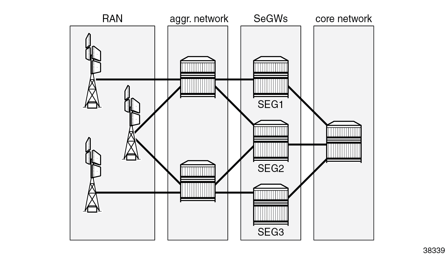
Radio access network (RAN) elements are opening IPsec tunnels toward SeGW cluster tunnel endpoint IP addresses. The RAN, aggregation network, and core network are emulated with standard routing nodes. For this deployment, assume that connectivity between elements is established using routing protocols and, as for a classic SeGW router, the public side where traffic is encrypted is built on top of a public-side VPRN, while private side (clear-text traffic) is associated with another VPRN. ISA2 or ESA resources manage encryption and decryption operations across the VPRN boundary.
This chapter describes configuration of SeGW elements, as well as MD-CLI commands for tracking the functionality of N:M nodes in the same redundancy domain (RD).
Configuration
Assume that IP connectivity is established across the IP network elements in the architecture. It is beyond the scope of this chapter to describe how traffic is carried from the RAN to the SeGW or from SeGW to the mobile packet core. Among the protocols and techniques that are required to speed up convergence of routing, the bidirectional forwarding detection (BFD) protocol is especially useful to keep network convergence time in a range compatible with mobile traffic use case.
ISA2 or ESA setup for N:M
The nodes participating in the IPsec domain have a standard setup for ISA2 or ESA resources.
SEG1 and SEG 2 can each be configured like a classic SeGW, as follows:
[gl:/configure isa]
A:admin@SEG1# info
    tunnel-group 1 {
        admin-state enable
        isa-scale-mode tunnel-limit-2k
        ipsec-responder-only true
        multi-active {
            isa 1/2 { }
            active-isa-number 1
        }
        reassembly {
            max-wait-time 1200
        }
        stats-collection {
            isa-dp-cpu-usage true
        }
    }
The active-isa-number command specifies the number of active encryption and decryption elements. Nokia recommends implementing the same number of ISA2 and ESA resources among the nodes participating in the RD, which allows for the DS node to activate the same number of ISA2 or ESA resources when failover occurs. However, a failover can occur even if the DS node has a lower number of ISA2 or ESA resources available in its local pool. This allows operators to save costs, but if the ISA2 ore ESA resources on the initial DA nodes were fully loaded, the DS node cannot host all tunnels and the protection is only partial.
N:M redundancy allows DS nodes to cover multiple TGs, and therefore, multiple RDs. DS nodes may have more ISA2 or ESA resources than the DA nodes, because the DS nodes should be able to cover one or more DA node failures, with a maximum of 16.
The output from SEG2 is the same as for SEG1.
SEG3 is configured as the DS node of the domain, where the configuration contains the tunnel-member-pool command:
[gl:/configure isa]
A:admin@SEG3# info
    tunnel-group 1 {
        admin-state enable
        isa-scale-mode tunnel-limit-2k
        ipsec-responder-only true
        multi-active {
            member-pool "MP1"
        }
        reassembly {
            max-wait-time 1200
        }
    }
    tunnel-member-pool "MP1" {
        isa 1/2 { }
    }
The tunnel-member-pool option defines the set of ISA2 or ESA resources used by the DS node during failures on active nodes. It is referenced in the tunnel group (TG) configuration, because multiple TGs can use the same tunnel member pool using the same set of ISA2 or ESA resources.
The output of the show isa tunnel-member-pool command lists ISA (ISA2 or ESA) members and their states. Under normal conditions, the ISA2 or ESA resource is not active on SEG3.
[gl:/configure isa]
A:admin@SEG3# /show isa tunnel-member-pool "MP1" detail

===============================================================================
ISA Tunnel Member Pool : MP1
Description            : (Not Specified)
Associated Tunnel Grps : 1
===============================================================================
Isa Members                   Active In Group     Last Configuration Change
-------------------------------------------------------------------------------
1/2                                               11/25/2022 12:10:14
-------------------------------------------------------------------------------
Number of Configured Entries: 1
Number of Active Entries: 0
===============================================================================
Redundancy domain configuration
The configuration of MC-IPsec as N:M starts by defining node roles and behavior. The configuration on SEG1 (with system IP address 192.0.2.1) is as follows:
[gl:/configure redundancy]
A:admin@SEG1# info
    multi-chassis {
        ipsec-domain 1 {
            admin-state enable
            designated-role active
            priority 250
            tunnel-group 1
        }
        peer 192.0.2.2  {
            admin-state enable
            sync {
                admin-state enable
                ipsec true
            }
            mc-ipsec {
                bfd-liveness true
                domain 1 {
                    admin-state enable
                }
            }
        }
        peer 192.0.2.3 {
            admin-state enable
            sync {
                admin-state enable
                ipsec true
            }
            mc-ipsec {
                bfd-liveness true
                domain 1 {
                    admin-state enable
                }
            }
        }
    }
The preceding configuration example shows a multi-chassis IPsec domain, where the following domain characteristics have been specified:
- domain number – must be shared across all the nodes joining the redundancy domain (RD)
- designated role – DA or DS
- priority – required by the multi-chassis IPsec mastership protocol (MIMPv2) when an operationally active (OA) node must be elected. Setting a higher priority for an SeGW increases the likelihood of it being elected as the OA. In this case, SEG1 has the highest priority and DA role, so it is elected OA for RD 1.
- tunnel group – must be defined as per the ISA2 or ESA setup. The TG is always mapped to the RD in a 1:1 relationship
-
peers – up to three peers can be added. While full-mesh peering between them is required, Nokia also recommends deploying highly redundant network paths between these peers.
Each peer has its own CLI tree where the following characteristics must be defined:
- the domain or domains the peer belongs to
- the synchronization state for IPsec
- whether BFD is applied to check peer liveliness.
- (optional) other parameters for keepalives, hold-time, and discovery-interval are configured with default values. Do not change these values unless a different setup is required under specific network conditions.
The configuration for the redundancy domain on SEG2 is the same as on SEG1, but with different IP addresses for peers and different priority:
A:admin@SEG2# info
    multi-chassis {
        ipsec-domain 1 {
            admin-state enable
            designated-role active
            priority 240
            tunnel-group 1
        }
        peer 192.0.2.1 {
            admin-state enable
            sync {
                admin-state enable
                ipsec true
            }
            mc-ipsec {
                bfd-liveness true
                domain 1 {
                    admin-state enable
                }
            }
        }
        peer 192.0.2.3 {
            admin-state enable
            sync {
                admin-state enable
                ipsec true
            }
            mc-ipsec {
                bfd-liveness true
                domain 1 {
                    admin-state enable
                }
            }
        }
    }
The designated role of SEG2 is active, which means SEG2 behaves similarly to the 1:1 model where tunnel states are synchronized with SEG1 and immediately pushed to ISA2 or ESA resources. This behavior allows for a very quick failover when SEG1 experiences a failure.
The priority is 240, which is lower than for SEG1. As a result, SEG1 receives node role DA and is operationally active (OA) while SEG2 receives node role DA and is operationally standby (OS).
The RD configuration for DS SEG3 is as follows:
[gl:/configure redundancy multi-chassis]
A:admin@SEG3# info
    ipsec-domain 1 {
        admin-state enable
        designated-role standby
        priority 230
        tunnel-group 1
    }
    peer 192.0.2.1 {
        admin-state enable
        sync {
            admin-state enable
            ipsec true
        }
        mc-ipsec {
            bfd-liveness true
            domain 1 {
                admin-state enable
            }
        }
    }
    peer 192.0.2.2 {
        admin-state enable
        sync {
            admin-state enable
            ipsec true
        }
        mc-ipsec {
            bfd-liveness true
            domain 1 {
                admin-state enable
            }
        }
    }
The peer configuration is similar to those of other nodes where BFD liveliness is enabled.
The designated role is standby (DS). The default value in the configuration is not shown from the info command.
The priority is 230 but the node role is DS. The DS node will not become OA because the DA role of SEG1 and SEG2 always prevails when electing the OA, regardless of priority value. Therefore, a DS node can become OA only if there are no DA nodes available in the domain.
After the setup of MC IPsec RD is completed across all the nodes, show commands can be used to track RD behavior and state:
A:admin@SEG1# show redundancy multi-chassis ipsec-domain 1

===============================================================================
Multi-Chassis IPsec Domain: 1
===============================================================================
Designated Role    : active             Priority           : 250
Tunnel Group       : 1                  Revertive          : false
Admin State        : Up                 Protection Status  : nominal
Router Id          : 192.0.2.1          Current Active     : 192.0.2.1
Activity State     : active
===============================================================================

===============================================================================
Domain 1 Adjacencies
===============================================================================
Peer                                        Oper    Remote       Remote
  Router-Id                                 State   Activity     Designated
                                                    State        Role
-------------------------------------------------------------------------------
192.0.2.2                                     Up      standby      active
  192.0.2.2
192.0.2.3                                     Up      standby      standby
  192.0.2.3
-------------------------------------------------------------------------------
Domain Adjacency Entries found: 2
===============================================================================

===============================================================================
Multi-Chassis Tunnel Statistics
===============================================================================
                              Static              Dynamic
-------------------------------------------------------------------------------
Installed                     0                   7
Installing                    0                   0
Standby Dormant               0                   0
Awaiting Config               0                   0
Failed                        0                   0
===============================================================================
The output shows important information about the redundancy domain:
- the designated role of the node – active or standby
- the activity state based on fault conditions – active or standby
- the protection status – "nominal" means that the nodes are synchronized.
- the domain adjacencies – list of peers and their activity state and designated role
- the tunnel statistics – in this case, seven dynamic tunnels are established
The same show command executed on SEG2 provides similar output, with differences for the priority and the designated role. The seven tunnels are shown in the "Installed" state because SEG2 is a DA node.
The same show command on DS SEG3 shows the following:
A:admin@SEG3# show redundancy multi-chassis ipsec-domain 1

===============================================================================
Multi-Chassis IPsec Domain: 1
===============================================================================
Designated Role    : standby            Priority           : 230
Tunnel Group       : 1                  Revertive          : false
Admin State        : Up                 Protection Status  : nominal
Router Id          : 192.0.2.3          Current Active     : 192.0.2.1
Activity State     : standby
===============================================================================

===============================================================================
Domain 1 Adjacencies
===============================================================================
Peer                                        Oper    Remote       Remote
  Router-Id                                 State   Activity     Designated
                                                    State        Role
-------------------------------------------------------------------------------
192.0.2.1                                     Up      active       active
  192.0.2.1
192.0.2.2                                     Up      standby      active
  192.0.2.2
-------------------------------------------------------------------------------
Domain Adjacency Entries found: 2
===============================================================================

===============================================================================
Multi-Chassis Tunnel Statistics
===============================================================================
                              Static              Dynamic
-------------------------------------------------------------------------------
Installed                     0                   0
Installing                    0                   0
Standby Dormant               0                   7
Awaiting Config               0                   0
Failed                        0                   0
===============================================================================
Relevant information from the SEG3 CLI output, apart from the activity state, the designated role, and the peer’s state, is the tunnel state, which is now marked as "Standby Dormant".
Tunnels on SEG3 are not installed on the ISA2 or ESA; rather, they are stored in the router CPM and are kept ready to be offloaded on the ISA2 or ESA resources connected to the router. These tunnels are offloaded as soon as SEG3 becomes OA, following a node reboot, failure, or manual switchover.
Services configuration
The tunnels opened by RAN elements are terminated in a public-side VPRN IP address called TEIP (the public side can also be made on a IES service). Assume that the RAN nodes are using a single tunnel setup with a single IKE_SA, whereas the Child_SA’s number is specific to the deployment. The configuration of this public side VPRN is the same for all three nodes and follows the standard SeGW setup:
[gl:/configure service vprn "100"]
A:admin@SEG1# info
    vprn "100" {
        admin-state enable
        description "public side"
        customer "1"
        ipsec {
            multi-chassis-shunt-interface "to_SEG2_Shunt" {
                next-hop {
                    address 10.1.12.2
                }
            }
            multi-chassis-shunt-interface "to_SEG3_Shunt" {
                next-hop {
                    address 10.1.13.2
                }
            }
            multi-chassis-shunting-profile "MCSPROF1" {
                peer 192.0.2.2 {
                    multi-chassis-shunt-interface "to_SEG2_Shunt"
                }
                peer 192.0.2.3 {
                    multi-chassis-shunt-interface "to_SEG3_Shunt"
                }
            }
        }
        interface "PUBLIC1" {
            multi-chassis-shunting-profile "MCSPROF1"
            sap tunnel-1.public:100 {
                ipsec-gateway "IPSECGW1" {
                    admin-state enable
                    default-tunnel-template 1
                    ike-policy 1
                    pre-shared-key "uCLxzS3PxoW0foPjmAKJ/Wv41hy6O3H76tg=" hash2
                    default-secure-service {
                        service-name "200"
                        interface "PRIVATE1"
                    }
                    local {
                        gateway-address 10.51.100.1
                    }
                }
            }
            ipv4 {
                primary {
                    address 198.51.100.2
                    prefix-length 24
                }
            }
        }
        interface "to_SEG2_Shunt" {
            spoke-sdp 2000:1 {
            }
            ipv4 {
                primary {
                    address 10.1.12.1
                    prefix-length 30
                }
            }
        }
        interface "to_SEG3_Shunt" {
            spoke-sdp 3000:1 {
            }
            ipv4 {
                primary {
                    address 10.1.13.1
                    prefix-length 30
                }
            }
        }
        ospf 0 {
            export-policy ["EXPORT_OSPF"]
        }
The parts of the configuration that are exclusive of N:M are those related to shunt-link setup.
The multi-chassis-shunting-profile command can be found under the ipsec configuration for the IES or VPRN service, where the multi-chassis shunting (MCS) profile is required to map each peer to a dedicated shunt interface. The MCS profile is referenced under the interface where the IPsec gateway is configured. In this scenario, peer 192.0.2.2 is reached through the to_SEG2_Shunt interface, which is defined under the same VPRN as an interface built on top of sdp:2000:1.
A full mesh of shunt interfaces is made across the RD, for both public and private side services.
A:admin@SEG1# show ipsec multi-chassis-shunt-interface service "100"

===============================================================================
IPsec Multi-Chassis Shunt Interfaces
===============================================================================
Service Id  MC Shunt Interface Name          Next Hop                 Resolved
-------------------------------------------------------------------------------
100         to_SEG2_Shunt                    10.1.12.2                Yes
100         to_SEG3_Shunt                    10.1.13.2                Yes
-------------------------------------------------------------------------------
No. of IPsec MC Shunt Interfaces: 2
===============================================================================
The show ipsec multi-chassis-shunt-interface service command shows the liveliness of shunt interfaces and information on the next-hop resolution, whereas the show ipsec multi-chassis-shunting-profile service command provides a summary of the MCS profile and associated peers:
A:admin@SEG1# show ipsec multi-chassis-shunting-profile service "100"

===============================================================================
Multi-Chassis Shunting Profile Params Entries
===============================================================================
Service Id  MC Shunting Profile Name                 MC Shunt Interface Name
            Peer
-------------------------------------------------------------------------------
100         MCSPROF1                                 to_SEG2_Shunt
            192.0.2.2
100         MCSPROF1                                 to_SEG3_Shunt
            192.0.2.3
-------------------------------------------------------------------------------
No. of IPsec MC Shunting Profile Params Entries: 2
===============================================================================
The SDP full mesh must be configured on both sides, as shown in the figure SDP full mesh.
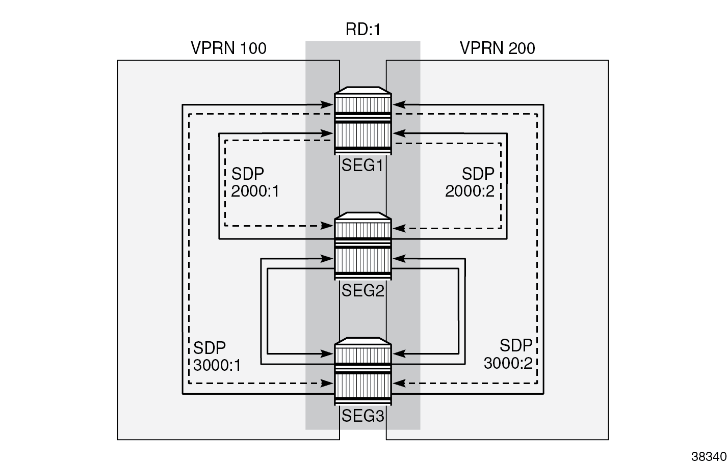
The shunt link can be built from a standard spoke SDP or from a port-based interface. In this example, the following spoke SDPs are used in the public-side VPRN 100:
A:admin@SEG1# show service id "100" sdp

===============================================================================
Services: Service Destination Points
===============================================================================
SdpId            Type     Far End addr    Adm     Opr       I.Lbl     E.Lbl
-------------------------------------------------------------------------------
2000:1           Spok     192.0.2.2       Up      Up        524285    524285
3000:1           Spok     192.0.2.3       Up      Up        524283    524285
-------------------------------------------------------------------------------
Number of SDPs : 2
-------------------------------------------------------------------------------
===============================================================================
The show output for the private-side VPRN 200 looks similar to that for the public-side VPRN, except for the SDP IDs and label values:
A:admin@SEG1# show service id "200" sdp

===============================================================================
Services: Service Destination Points
===============================================================================
SdpId            Type     Far End addr    Adm     Opr       I.Lbl     E.Lbl
-------------------------------------------------------------------------------
2000:2           Spok     192.0.2.2       Up      Up        524284    524284
3000:2           Spok     192.0.2.3       Up      Up        524282    524284
-------------------------------------------------------------------------------
Number of SDPs : 2
-------------------------------------------------------------------------------
===============================================================================
There are no routing policy changes from the 1:1 MC-IPsec cluster, although this example could have a more complex routing setup, considering that the number of routers in a domain is higher than in the 1:1 model. The following configuration shows the SEG1-2-3 export policy used on the public side where the OSPF protocol is used under VPRN 100:
[gl:/configure policy-options policy-statement "EXPORT_OSPF"]
A:admin@SEG1# info
    description "EXPORT TEIP OSPF - PUBLIC SIDE"
    entry 10 {
        from {
            state ipsec-master-with-peer
            protocol {
                name [ipsec]
            }
        }
        action {
            action-type accept
            tag 100
            metric {
                set 30
            }
        }
    }
    entry 20 {
        from {
            state ipsec-non-master
            protocol {
                name [ipsec]
            }
        }
        action {
            action-type accept
            tag 100
            metric {
                set 190
            }
        }
    }
    entry 30 {
        from {
            state ipsec-master-without-peer
            protocol {
                name [ipsec]
            }
        }
        action {
            action-type accept
            tag 100
            metric {
                set 40
            }
        }
    }
    default-action {
        action-type reject
    }
On SEG2, only the metrics are different and are aligned with DA priorities:
[gl:/configure policy-options policy-statement "EXPORT_OSPF"]
A:admin@SEG2# info
    policy-statement "EXPORT_OSPF" {
        description "EXPORT TEIP OSPF - PUBLIC SIDE"
        entry 10 {
            from {
                state ipsec-master-with-peer
                protocol {
                    name [ipsec]
                }
            }
            action {
                action-type accept
                tag 200
                metric {
                    set 60
                }
            }
        }
        entry 20 {
            from {
                state ipsec-non-master
                protocol {
                    name [ipsec]
                }
            }
            action {
                action-type accept
                tag 200
                metric {
                    set 190
                }
            }
        }
        entry 30 {
            from {
                state ipsec-master-without-peer
                protocol {
                    name [ipsec]
                }
            }
            action {
                action-type accept
                tag 200
                metric {
                    set 50
                }
            }
        }
        default-action {
            action-type reject
        }
    }
On SEG3, the export policy is as follows:
[gl:/configure policy-options policy-statement "EXPORT_OSPF"]
A:admin@SEG3# info
    policy-statement "EXPORT_OSPF" {
        description "EXPORT TEIP OSPF - PUBLIC SIDE"
        entry 10 {
            from {
                state ipsec-master-with-peer
                protocol {
                    name [ipsec]
                }
            }
            action {
                action-type accept
                tag 300
                metric {
                    set 90
                }
            }
        }
        entry 20 {
            from {
                state ipsec-non-master
                protocol {
                    name [ipsec]
                }
            }
            action {
                action-type accept
                tag 300
                metric {
                    set 195
                }
            }
        }
        entry 30 {
            from {
                state ipsec-master-without-peer
                protocol {
                    name [ipsec]
                }
            }
            action {
                action-type accept
                tag 300
                metric {
                    set 60
                }
            }
        }
        default-action {
            action-type reject
        }
    }
The export policy on the private-side VPRN is made with the same concept as the public side, but is not shown here.
On the private side of SeGWs, a different VPRN is required, as per standard IPsec configuration. The private-side VPRN configuration on SEG1 is as follows:
[gl:/configure service vprn "200"]
A:admin@SEG1# info
    admin-state enable
    description "private segw testing"
    customer "1"
    ipsec {
        multi-chassis-shunt-interface "to_SEG2_Shunt" {
            next-hop {
                address 10.2.12.2
            }
        }
        multi-chassis-shunt-interface "to_SEG3_Shunt" {
            next-hop {
                address 10.2.13.2
            }
        }
        multi-chassis-shunting-profile "MCSPROF1" {
            peer 192.0.2.2 {
                multi-chassis-shunt-interface "to_SEG2_Shunt"
            }
            peer 192.0.2.3 {
                multi-chassis-shunt-interface "to_SEG3_Shunt"
            }
        }
    }
    bgp-ipvpn {
        mpls {
            admin-state enable
            route-distinguisher "300:4"
        }
    }
    interface "PRIVATE1" {
        tunnel true
        multi-chassis-shunting-profile "MCSPROF1"
        sap tunnel-1.private:100 {
        }
    }
    interface "to_SEG2_Shunt" {
        ipv4 {
            primary {
                address 10.2.12.1
                prefix-length 30
            }
        }
        spoke-sdp 2000:2 {
        }
    }
    interface "to_SEG3_Shunt" {
        ipv4 {
            primary {
                address 10.2.13.1
                prefix-length 30
            }
        }
        spoke-sdp 3000:2 {
        }
    }
As the configuration shows, the same setup of shunt links is required on the private side to allow path resiliency in case of faults for the traffic going downstream from core toward the RAN.
Failure scenario – active node experiences a power failure
N:M can be triggered by different fault conditions, such as a complete node failure, an ISA2 or ESA failure, or a manual switchover executed with the tools command. In this scenario, complete node failures are simulated. When SEG1 experiences a node failure, SEG2 takes over. When SEG2 fails too, SEG3 takes over and remains the only node with active tunnels.
The initial scenario has SEG1 and SEG2 configured as DA nodes, while SEG3 is the DS node for the domain configured as ipsec-domain 1. The state can be verified with the show redundancy multi-chassis ipsec-domain 1 command (as shown above in the Redundancy domain configurationsection ).
As soon as SEG1 experiences a node failure, SEG2 takes over:
A:admin@SEG2# show redundancy multi-chassis ipsec-domain 1

===============================================================================
Multi-Chassis IPsec Domain: 1
===============================================================================
Designated Role    : active             Priority           : 240
Tunnel Group       : 1                  Revertive          : false
Admin State        : Up                 Protection Status  : notReady
Router Id          : 192.0.2.2          Current Active     : 192.0.2.2
Activity State     : active
===============================================================================

===============================================================================
Domain 1 Adjacencies
===============================================================================
Peer                                        Oper    Remote       Remote
  Router-Id                                 State   Activity     Designated
                                                    State        Role
-------------------------------------------------------------------------------
192.0.2.1                                   Down    unknown      unknown
  0.0.0.0
192.0.2.3                                   Up      standby      standby
  192.0.2.3
-------------------------------------------------------------------------------
Domain Adjacency Entries found: 2
===============================================================================

===============================================================================
Multi-Chassis Tunnel Statistics
===============================================================================
                              Static              Dynamic
-------------------------------------------------------------------------------
Installed                     0                   7
Installing                    0                   0
Standby Dormant               0                   0
Awaiting Config               0                   0
Failed                        0                   0
===============================================================================
Although the protection status, as seen from SEG2 and SEG3, is initially "notReady", it changes to "nominal" after few minutes. From the SEG2 and SEG3 point of view, SEG1 is unreachable, and its activity state remains unknown. Log 99 also records the failure event:
A:admin@SEG2# show log log-id 99

===============================================================================
Event Log 99 log-name 99
===============================================================================
Description : Default System Log
Memory Log contents  [size=500   next event=187  (not wrapped)]

186 2022/12/13 14:05:32.534 UTC WARNING: MC_REDUNDANCY #2047 Base MC-IPSEC-DOMAIN 1
"Protection status for the multi-chassis ipsec domain 1 changed to nominal"

185 2022/12/13 14:02:19.611 UTC MINOR: VRTR #2061 Base 192.0.2.1
"BFD: Local Discriminator 1 BFD session on node 192.0.2.1 is down due to noHeartBeat "

---snip---

179 2022/12/13 14:02:19.124 UTC WARNING: MC_REDUNDANCY #2004 Base
"The Sync status of peer 192.0.2.1 changed to outOfSync"

178 2022/12/13 14:02:18.746 UTC WARNING: MC_REDUNDANCY #2046 Base MC-IPSEC-DOMAIN 1
"Multi-chassis ipsec domain 1 local activity state changed from standby to active because an inter-chassis link went down. The active router in the domain is 192.0.2.2."
Next, SEG2 also experiences a full node failure, and SEG3 takes over:
A:admin@SEG3# show redundancy multi-chassis ipsec-domain 1

===============================================================================
Multi-Chassis IPsec Domain: 1
===============================================================================
Designated Role    : standby            Priority           : 230
Tunnel Group       : 1                  Revertive          : false
Admin State        : Up                 Protection Status  : notReady
Router Id          : 192.0.2.3          Current Active     : 192.0.2.3
Activity State     : eligible
===============================================================================

===============================================================================
Domain 1 Adjacencies
===============================================================================
Peer                                        Oper    Remote       Remote
  Router-Id                                 State   Activity     Designated
                                                    State        Role
-------------------------------------------------------------------------------
192.0.2.1                                   Down    unknown      unknown
  0.0.0.0
192.0.2.2                                   Down    unknown      unknown
  0.0.0.0
-------------------------------------------------------------------------------
Domain Adjacency Entries found: 2
===============================================================================

===============================================================================
Multi-Chassis Tunnel Statistics
===============================================================================
                              Static              Dynamic
-------------------------------------------------------------------------------
Installed                     0                   7
Installing                    0                   0
Standby Dormant               0                   0
Awaiting Config               0                   0
Failed                        0                   0
===============================================================================
Both SEG1 and SEG2 are seen as operationally down with an unknown activity state. On SEG3, the tunnel states have been copied from the CPM to the ISA2 or ESA entities and are now shown as "Installed", rather than "Standby Dormant". As soon as SEG1 or SEG2 are back up, the revertive flag configured under the ipsec-domain command determines if the tunnels are kept on the current active DS node or if they are moved back to SEG1 ownership.
Failure scenario – using the tools command line
A planned failure condition is commonly seen when executing software upgrades or hardware maintenance on SeGW nodes, which leverages the tools command line utility to move tunnels toward other peering nodes.
The initial state is the same as for the previous example where SEG1 is initially the operationally active DA.
The following tools command triggers a switchover and therefore causes all the tunnels installed on the operationally active DA node to move on another node in the domain, selected by the auto flag in this case.
A:admin@SEG1# tools perform redundancy multi-chassis mc-ipsec force-switchover domain 1 auto now
To specify a peer IP address among those available in the domain, the to <peer_ip> option could be used instead of auto.
The following output shows the domain state as seen from SEG1 after the execution of the tools command:
A:admin@SEG1# show redundancy multi-chassis ipsec-domain 1

===============================================================================
Multi-Chassis IPsec Domain: 1
===============================================================================
Designated Role    : active             Priority           : 250
Tunnel Group       : 1                  Revertive          : false
Admin State        : Up                 Protection Status  : notReady
Router Id          : 192.0.2.1          Current Active     : 192.0.2.2
Activity State     : standby
===============================================================================

===============================================================================
Domain 1 Adjacencies
===============================================================================
Peer                                        Oper    Remote       Remote
  Router-Id                                 State   Activity     Designated
                                                    State        Role
-------------------------------------------------------------------------------
192.0.2.2                                   Up      active       active
  192.0.2.2
192.0.2.3                                   Up      standby      standby
  192.0.2.3
-------------------------------------------------------------------------------
Domain Adjacency Entries found: 2
===============================================================================

===============================================================================
Multi-Chassis Tunnel Statistics
===============================================================================
                              Static              Dynamic
-------------------------------------------------------------------------------
Installed                     0                   7
Installing                    0                   0
Standby Dormant               0                   0
Awaiting Config               0                   0
Failed                        0                   0
===============================================================================
As shown in the output, the current active node is SEG2 (192.0.2.2). The auto flag forced all the traffic to move across the second preferred active node in the domain, which is SEG2.
The protection status, as seen from SEG2, changes to "nominal" after a few minutes:
A:admin@SEG2# show redundancy multi-chassis ipsec-domain 1

===============================================================================
Multi-Chassis IPsec Domain: 1
===============================================================================
Designated Role    : active             Priority           : 240
Tunnel Group       : 1                  Revertive          : false
Admin State        : Up                 Protection Status  : nominal
Router Id          : 192.0.2.2          Current Active     : 192.0.2.2
Activity State     : active
===============================================================================

===============================================================================
Domain 1 Adjacencies
===============================================================================
Peer                                        Oper    Remote       Remote
  Router-Id                                 State   Activity     Designated
                                                    State        Role
-------------------------------------------------------------------------------
192.0.2.1                                     Up      standby      active
  192.0.2.1
192.0.2.3                                     Up      standby      standby
  192.0.2.3
-------------------------------------------------------------------------------
Domain Adjacency Entries found: 2
===============================================================================

===============================================================================
Multi-Chassis Tunnel Statistics
===============================================================================
                              Static              Dynamic
-------------------------------------------------------------------------------
Installed                     0                   7
Installing                    0                   0
Standby Dormant               0                   0
Awaiting Config               0                   0
Failed                        0                   0
===============================================================================
After maintenance operations on SEG1 have been completed and the node is operational (which can be verified using the show commands described in this chapter), the operator reverts services and traffic back to SEG1. For this purpose and in this specific example, the same tools command can be used. The auto flag selects SEG1, according to its highest priority in the domain. If more predictability is required in the selection choice, the to <peer_ip> flag can be used, as in this example:
A:admin@SEG2# tools perform redundancy multi-chassis mc-ipsec force-switchover domain 1 to 192.0.2.1 now
Conclusion
N:M adds a level of redundancy to an already efficient redundancy model; it ensures that RAN elements stay connected to the core network under a wide range of failure conditions. SR OS uses a full set of commands to implement this feature, available for both classic and MD-CLI. N:M also gives network engineers and architects the capability to deploy SeGW services with greater flexibility; for example, to deploy super-resilient SeGW clusters to serve high-density RAN areas, or to introduce cost-optimized solutions with an acceptable level of automated fault recovery.