RSVP Signaled Point-to-Multipoint LSPs
This chapter provides information about RSVP-signaled point-to-multipoint LSPs.
Topics in this chapter include:
Applicability
This chapter was originally written for SR OS Release 7.0.R5, but the CLI in the current edition corresponds toSR OS Release 24.10.R2.
Overview
Point-to-MultiPoint (P2MP) Multi-Protocol Label Switching (MPLS) Label Switched Paths (LSPs) allow the source of multicast traffic to forward packets to one or many multicast receivers over a network without requiring a multicast protocol, such as Protocol Independent Multicast (PIM), to be configured in the network. A P2MP LSP tree is established in the control plane, and the path consists of a head-end node, one or many branch and bud nodes, and the leaf nodes. A bud node combines the roles of branch node and leaf node (for different source-to-leaf (S2L) LSPs). Packets injected by the head-end node are replicated in the data plane at the branching nodes before they are delivered to the leaf nodes.
Similar to point-to-point (P2P) LSPs, also P2MP LSPs are unidirectional, originating on a head-end node (the ingress LER) and terminating on one or more leaf nodes (the egress LERs). Resource Reservation Protocol (RSVP) is used as signaling protocol. A P2MP LSP is modeled as a set of root-to-leaf sub LSPs (S2L). Each S2L is modeled as a point-to-point LSP in the control plane. This means that each S2L has its own PATH/RESV messages. This is called the de-aggregated method.
The forwarding of multicast packets to the LSP tree was initially based on static multicast routes, and has evolved to BGP-based VPN routes afterward (but the latter is beyond the scope of this chapter). In this example, forwarding multicast packets is done over P2MP RSVP LSPs in the base router instance.
RSVP signaled P2MP LSPs can have fast reroute (FRR) enabled. The FRR facility method (one-to-many) with link protection is supported.
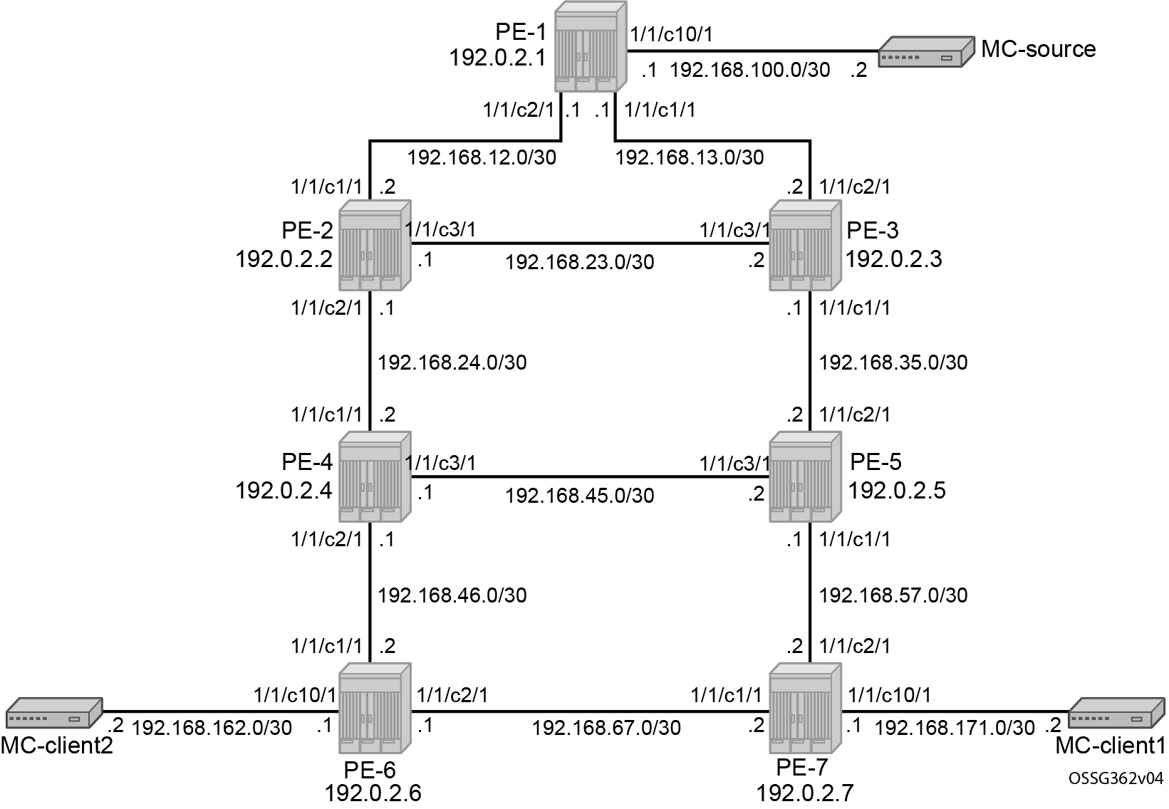
P2MP example topology shows the P2MP example topology with seven PEs. The multicast source is connected to PE-1, multicast client 1 is attached to PE-7, and multicast client 2 to PE-6, as follows:
Configuration
The following sections describe the steps that must be performed to configure RSVP signaled point-to-multipoint LSPs.
Configuring the IP/MPLS network
The system addresses and Layer 3 interface addresses are configured according to P2MP example topology. An Interior Gateway Protocol (IGP) is needed to distribute routing information to all PEs. In this case, the IGP is OSPF using the backbone area 0.0.0.0. A configuration example is shown for PE-1. A similar configuration is needed on all PEs.
# on PE-1:
configure
    router Base
        interface "int-PE-1-PE-2"
            address 192.168.12.1/30
            port 1/1/c2/1:1000
        exit
        interface "int-PE-1-PE-3"
            address 192.168.13.1/30
            port 1/1/c1/1:1000
        exit
        interface "system"
            address 192.0.2.1/32
        exit
        ospf 0
            traffic-engineering
            area 0.0.0.0
                interface "system"
                exit
                interface "int-PE-1-PE-2"
                    interface-type point-to-point
                exit
                interface "int-PE-1-PE-3"
                    interface-type point-to-point
                exit
            exit
            no shutdown
        exit
Because FRR is enabled for the P2MP LSP, Traffic Engineering (TE) is needed on the IGP. With TE enabled, OSPF generates opaque link state advertisements (LSAs) which are collected in a Traffic Engineering Database (TED), separate from the traditional OSPF topology database. OSPF interfaces are set up as type point-to-point to improve convergence, because no Designated Router/Backup Designated Router (DR/BDR) election process is done. However, convergence is out of the scope of this chapter.
The following command verifies that the OSPF neighbors are up (state Full):
*A:PE-1# show router ospf neighbor

===============================================================================
Rtr Base OSPFv2 Instance 0 Neighbors
===============================================================================
Interface-Name                   Rtr Id          State      Pri  RetxQ   TTL
   Area-Id
-------------------------------------------------------------------------------
int-PE-1-PE-2                    192.0.2.2       Full       1    0       36
   0.0.0.0
int-PE-1-PE-3                    192.0.2.3       Full       1    0       36
   0.0.0.0
-------------------------------------------------------------------------------
No. of Neighbors: 2
===============================================================================
The route table shows the Layer 3 interface addresses/subnets that are known on the PEs. The route table on head-end PE-1 is as follows:
*A:PE-1# show router route-table

===============================================================================
Route Table (Router: Base)
===============================================================================
Dest Prefix[Flags]                            Type    Proto     Age        Pref
      Next Hop[Interface Name]                                    Metric
-------------------------------------------------------------------------------
192.0.2.1/32                                  Local   Local     00h00m55s  0
       system                                                       0
192.0.2.2/32                                  Remote  OSPF      00h00m43s  10
       192.168.12.2                                                 1
192.0.2.3/32                                  Remote  OSPF      00h00m32s  10
       192.168.13.2                                                 1
192.0.2.4/32                                  Remote  OSPF      00h00m23s  10
       192.168.12.2                                                 2
192.0.2.5/32                                  Remote  OSPF      00h00m17s  10
       192.168.13.2                                                 2
192.0.2.6/32                                  Remote  OSPF      00h00m09s  10
       192.168.12.2                                                 3
192.0.2.7/32                                  Remote  OSPF      00h00m09s  10
       192.168.13.2                                                 3
192.168.12.0/30                               Local   Local     00h00m55s  0
       int-PE-1-PE-2                                                0
192.168.13.0/30                               Local   Local     00h00m55s  0
       int-PE-1-PE-3                                                0
192.168.23.0/30                               Remote  OSPF      00h00m43s  10
       192.168.12.2                                                 2
192.168.24.0/30                               Remote  OSPF      00h00m43s  10
       192.168.12.2                                                 2
192.168.35.0/30                               Remote  OSPF      00h00m32s  10
       192.168.13.2                                                 2
192.168.45.0/30                               Remote  OSPF      00h00m23s  10
       192.168.12.2                                                 3
192.168.46.0/30                               Remote  OSPF      00h00m23s  10
       192.168.12.2                                                 3
192.168.57.0/30                               Remote  OSPF      00h00m17s  10
       192.168.13.2                                                 3
192.168.67.0/30                               Remote  OSPF      00h00m09s  10
       192.168.12.2                                                 4
-------------------------------------------------------------------------------
No. of Routes: 16
Flags: n = Number of times nexthop is repeated
       B = BGP backup route available
       L = LFA nexthop available
       S = Sticky ECMP requested
===============================================================================
The following command shows the contents of the forwarding information base (FIB) for IOM card slot 1:
*A:PE-1# show router fib 1

===============================================================================
FIB Display
===============================================================================
Prefix [Flags]                                              Protocol
  NextHop
-------------------------------------------------------------------------------
192.0.2.1/32                                                LOCAL
  192.0.2.1 (system)
192.0.2.2/32                                                OSPF
  192.168.12.2 (int-PE-1-PE-2)
192.0.2.3/32                                                OSPF
  192.168.13.2 (int-PE-1-PE-3)
192.0.2.4/32                                                OSPF
  192.168.12.2 (int-PE-1-PE-2)
192.0.2.5/32                                                OSPF
  192.168.13.2 (int-PE-1-PE-3)
192.0.2.6/32                                                OSPF
  192.168.12.2 (int-PE-1-PE-2)
192.0.2.7/32                                                OSPF
  192.168.13.2 (int-PE-1-PE-3)
192.168.12.0/30                                             LOCAL
  192.168.12.0 (int-PE-1-PE-2)
192.168.13.0/30                                             LOCAL
  192.168.13.0 (int-PE-1-PE-3)
192.168.23.0/30                                             OSPF
  192.168.12.2 (int-PE-1-PE-2)
192.168.24.0/30                                             OSPF
  192.168.12.2 (int-PE-1-PE-2)
192.168.35.0/30                                             OSPF
  192.168.13.2 (int-PE-1-PE-3)
192.168.45.0/30                                             OSPF
  192.168.12.2 (int-PE-1-PE-2)
192.168.46.0/30                                             OSPF
  192.168.12.2 (int-PE-1-PE-2)
192.168.57.0/30                                             OSPF
  192.168.13.2 (int-PE-1-PE-3)
192.168.67.0/30                                             OSPF
  192.168.12.2 (int-PE-1-PE-2)
-------------------------------------------------------------------------------
Total Entries : 16
-------------------------------------------------------------------------------
===============================================================================
On PE-1, the interface toward the multicast source is configured in an IES service. This could have been on a router interface instead.
# on PE-1:
configure
    service
        ies 1 name "IES 1" customer 1 create
            interface "int-PE-1-MC-source" create
                address 192.168.100.1/30
                sap 1/1/c10/1 create
                exit
            exit
            no shutdown
        exit
    exit
    router Base
        ospf 0
            area 0.0.0.0
                interface "int-PE-1-MC-source"
                    interface-type point-to-point
                    no shutdown
                exit
            exit
Similar IES services are configured on PE-7 and PE-6 for multicast client 1 and multicast client 2.
# on PE-7:
configure
    service
        ies 1 name "IES 1" customer 1 create
            interface "int-PE-7-MC-client1" create
                address 192.168.171.1/30
                sap 1/1/c10/1 create
                exit
            exit
            no shutdown
        exit
# on PE-6:
configure
    service
        ies 1 name "IES 1" customer 1 create
            interface "int-PE-6-MC-client2" create
                address 192.168.162.1/30
                sap 1/1/c10/1 create
                exit
            exit
            no shutdown
        exit
The next step in the process of setting up a P2MP LSP, is enabling the L3 interfaces in the MPLS and RSVP context on all involved PE nodes (from PE-1 to PE-7). By default, the system interface is put automatically within the MPLS and RSVP context. When an interface is put in the mpls context, SR OS copies it also in the rsvp context. Explicit enabling of mpls and rsvp context is done by the no shutdown command. The MPLS and RSVP configuration for PE-1 is as follows:
# on PE-1:
configure
    router Base
        mpls
            interface "int-PE-1-PE-2"
            exit
            interface "int-PE-1-PE-3"
            exit
            no shutdown
        exit
        rsvp
            no shutdown
        exit
Configuring P2MP RSVP LSP
P2MP LSP LSP-p2mp-1 with bypass tunnels shows the P2MP LSP LSP-p2mp-1 with FRR facility backup.
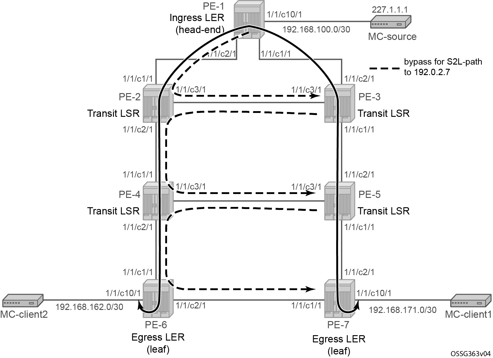
A P2MP LSP (LSP-p2mp-1) is set up from PE-1 acting as head-end node and PE-6 and PE-7 acting as leaf nodes. Because FRR is enabled, Constrained Shortest Path First (CSPF) is enabled to calculate the routes on the Traffic Engineering Database (TED). FRR facility method is used without node protection; the facility method stands for one-to-many, meaning that one bypass tunnel can protect a set of primary LSPs with similar backup constraints. When a link failure occurs on one of the active S2L paths, the Point of Local Repair (PLR) node pushes an additional MPLS label on the incoming MPLS packet before sending it into the bypass tunnel downstream toward the Merge Point (MP) node.
In the first example, the IGP OSPF calculates the path to the two destinations PE-6 and PE-7. The intermediate hops of the LSP are dynamically assigned by OSPF best route selection, so the S2L paths follow the IGP least cost path. Therefore, an empty MPLS path is configured without specifying any hops.
# on PE-1:
configure
    router Base
        mpls
            path "empty"
                no shutdown
            exit
The P2MP LSP "LSP-p2mp-1" is created on the ingress LER or head-end node (PE-1 in the example) and can be seen in following CLI output. A create-time keyword p2mp-lsp is added to the P2MP name to make a distinction in configuration between normal point-to-point LSPs and point-to-multipoint LSPs. A primary P2MP instance is initiated using the primary-p2mp-instance keyword accompanied with the P2MP instance name "p-LSP-p2mp-1". Within this primary P2MP instance, the different S2Ls are defined using the s2l-path keyword. The same MPLS path name can be used for different S2Ls as long as the destination is different (to command).
# on PE-1:
configure
    router Base
        mpls
            lsp "LSP-p2mp-1" p2mp-lsp
                from 192.0.2.1
                path-computation-method local-cspf
                fast-reroute facility
                    no node-protect
                exit
                primary-p2mp-instance "p-LSP-p2mp-1"
                    s2l-path "empty" to 192.0.2.6
                    exit
                    s2l-path "empty" to 192.0.2.7
                    exit
                exit
                no shutdown
            exit
On the head-end LER node of the P2MP LSP, several show commands can be used. The following command shows that the only P2MP LSP on PE-1 is LSP-p2mp-1 and the administrative and operational state of this P2MP LSP is up and FRR is enabled:
*A:PE-1# show router mpls p2mp-lsp

===============================================================================
MPLS P2MP LSPs (Originating)
===============================================================================
LSP Name                                            Tun     Fastfail  Adm  Opr
                                                    Id      Config
-------------------------------------------------------------------------------
LSP-p2mp-1                                          1       Yes       Up   Up
-------------------------------------------------------------------------------
LSPs : 1
===============================================================================
In this example, P2MP LSP "LSP-p2mp-1" has two active S2L paths: one toward leaf node PE-6 and one to leaf node PE-7. FRR is enabled and the FRR method is facility.
*A:PE-1# show router mpls p2mp-lsp "LSP-p2mp-1" detail

===============================================================================
MPLS P2MP LSPs (Originating) (Detail)
===============================================================================
Legend :
    + - Inherited
===============================================================================
-------------------------------------------------------------------------------
Type : Originating
-------------------------------------------------------------------------------
LSP Name   : LSP-p2mp-1
LSP Type        : P2mpLsp                   LSP Tunnel ID        : 1
LSP Index       : 1                         TTM Tunnel Id        : 1
From            : 192.0.2.1
To              : Not configured
Adm State       : Up                        Oper State           : Up
LSP Up Time     : 0d 00:00:00               LSP Down Time        : 0d 00:00:00
Transitions     : 1                         Path Changes         : 1
Retry Limit     : 0                         Retry Timer          : 30 sec
Signaling       : RSVP                      Resv. Style          : SE
Hop Limit       : 255                       Negotiated MTU       : n/a
Adaptive        : Enabled                   ClassType            : 0
FastReroute     : Enabled                   Oper FR              : Enabled
FR Method       : Facility                  FR Hop Limit         : 16
FR Node Protect : Disabled                  FR Prop Adm Grp      : Disabled
FR Object       : Enabled
PathCompMethod  : local-cspf                ADSPEC               : Disabled
FallbkPathComp  : not-applicable
Metric          : Disabled                  Metric Type          : igp
Load Bal Wt     : N/A                       ClassForwarding      : Disabled
Include Grps    :                           Exclude Grps         :
None                                           None
Least Fill      : Disabled                  Soft Preemption      : Disabled

Revert Timer    : Disabled                  Next Revert In       : N/A
Auto BW         : Disabled
LdpOverRsvp     : Disabled
VprnAutoBind    : Disabled
IGP Shortcut    : Disabled                  BGP Shortcut         : Disabled
IGP LFA         : Disabled                  IGP Rel Metric       : Disabled
AllowSrOverSrte : Disabled
BGPTransTun     : Disabled
Oper Metric     : Disabled
Prop Adm Grp    : Disabled

P2MPInstance    : p-LSP-p2mp-1
                                            P2MP-Inst-type       : Primary
S2L Cfg Counter : 2                         S2L Oper Counter     : 2
S2L-Name        : empty
                                            To                   : 192.0.2.6
S2L-Name        : empty
                                            To                   : 192.0.2.7
===============================================================================
*A:PE-1# show router mpls p2mp-info

===============================================================================
MPLS P2MP Cross Connect Information
===============================================================================
-------------------------------------------------------------------------------
S2L:LSP-p2mp-1::empty
-------------------------------------------------------------------------------
Source IP Address    : 192.0.2.1             Tunnel ID     : 1
P2MP ID              : 0                     Lsp ID        : 52736
To                   : 192.0.2.6
Out Interface        : 1/1/c2/1:1000         Out Label     : 524287
Num. of S2ls         : 1
-------------------------------------------------------------------------------
S2L:LSP-p2mp-1::empty
-------------------------------------------------------------------------------
Source IP Address    : 192.0.2.1             Tunnel ID     : 1
P2MP ID              : 0                     Lsp ID        : 52736
To                   : 192.0.2.7
Out Interface        : 1/1/c1/1:1000         Out Label     : 524287
Num. of S2ls         : 1
-------------------------------------------------------------------------------
P2MP Cross-connect instances : 2
===============================================================================
*A:PE-1# show router mpls p2mp-lsp "LSP-p2mp-1" p2mp-instance "p-LSP-p2mp-1"

===============================================================================
MPLS P2MP Instance (Originating)
===============================================================================
-------------------------------------------------------------------------------
Type : Originating
-------------------------------------------------------------------------------
LSP Name    : LSP-p2mp-1
P2MP ID         : 0                         LSP Tunnel ID        : 1
Adm State       : Up                        Oper State           : Up

P2MPInstance    : p-LSP-p2mp-1
                                            P2MP-Inst-type       : Primary
P2MP Inst Id    : 1                         P2MP Lsp Id          : 52736
Inst Admin      : Up                        Inst Oper            : Up
Inst Up Time    : 0d 00:00:00               Inst Dn Time         : 0d 00:00:00
Hop Limit       : 255                       Adaptive             : Enabled
Record Route    : Record                    Record Label         : Record
Setup Priority  : 7                         Hold Priority        : 0
Include Grps    :                           Exclude Grps         :
None                                           None
Bandwidth       : No Reservation            Oper Bw              : 0 Mbps
S2L-Name        : empty
                                            To                   : 192.0.2.6
S2L Admin       : Up                        S2L Oper             : Up
S2L-Name        : empty
                                            To                   : 192.0.2.7
S2L Admin       : Up                        S2L Oper             : Up
-------------------------------------------------------------------------------
P2MP instances : 1
===============================================================================
As long as one S2L path is operationally up (show router mpls p2mp-lsp <p2mp-lsp-name> p2mp-instance <p2mp-instance-name>) , the operational state of the P2MP LSP is up.
FRR information can be displayed in detail for each S2L path. From this moment onward, the focus is on the S2L path toward PE-7. The following command shows that link protection is present for the link between PE-1 and PE-3, for the link between PE-3 and PE-5, and for the link between PE-5 and PE-7 (as indicated by the ‛@’-reference inside the list of actual hops).
*A:PE-1# show router mpls p2mp-lsp "LSP-p2mp-1" p2mp-instance "p-LSP-p2mp-1" s2l empty to 192.0.2.7 detail

===============================================================================
MPLS LSP LSP-p2mp-1 S2L empty (Detail)
===============================================================================
Legend :
    @ - Detour Available                          # - Detour In Use
    b - Bandwidth Protected                       n - Node Protected
    S - Strict                                    L - Loose
    A - ABR
    s - Soft Preemption
===============================================================================
LSP Name         : LSP-p2mp-1
S2L LSP ID       : 52736
P2MP ID          : 0                       S2L Grp Id        : 2
Admin State      : Up                      Oper State        : Up
S2L State:       : Active                                    :
S2L Name         : empty
To               : 192.0.2.7
S2L Admin        : Up                      S2L Oper          : Up
OutInterface     : 1/1/c1/1:1000           Out Label         : 524287
S2L Up Time      : 0d 00:01:44             S2L Dn Time       : 0d 00:00:00
RetryAttempt     : 0                       NextRetryIn       : 0 sec
S2L Trans        : 1                       CSPF Queries      : 1
Failure Code     : noError                 Failure Node      : n/a
Inter-area       : False
ExplicitHops     :
    No Hops Specified
Actual Hops      :
    192.168.13.1(192.0.2.1) @                    Record Label        : N/A
 -> 192.168.13.2(192.0.2.3) @                    Record Label        : 524287
 -> 192.168.35.2(192.0.2.5) @                    Record Label        : 524287
 -> 192.168.57.2(192.0.2.7)                      Record Label        : 524287
ComputedHops     :
    192.168.13.1(S)
 -> 192.168.13.2(S)
 -> 192.168.35.2(S)
 -> 192.168.57.2(S)
LastResignal     : n/a
===============================================================================
More in detail, show router mpls bypass-tunnel detail can be used. The list of actual hops provides the explicit hops of the bypass tunnel used to avoid the direct link between PE-1 and PE-3. On node PE-1, the MPLS path from PE-1 to PE-3 via PE-2 is followed (see P2MP LSP LSP-p2mp-1 with bypass tunnels).
*A:PE-1# show router mpls bypass-tunnel detail

===============================================================================
MPLS Bypass Tunnels (Detail)
===============================================================================
---snip---
-------------------------------------------------------------------------------
bypass-link192.168.13.2-61441
-------------------------------------------------------------------------------
To             : 192.168.23.2        State               : Up
Out I/F        : 1/1/c2/1:1000       Out Label           : 524285
Up Time        : 0d 00:04:23         Active Time         : n/a
Reserved BW    : 0 Kbps              Protected LSP Count : 1
Type           : P2mp                Bypass Path Cost    : 2
Setup Priority : 7                   Hold Priority       : 0
Class Type     : 0
Exclude Node   : None                Inter-Area          : False
Computed Hops  :
    192.168.12.1(S)                  Egress Admin Groups : None
 -> 192.168.12.2(S)                  Egress Admin Groups : None
 -> 192.168.23.2(S)                  Egress Admin Groups : None
Actual Hops    :
    192.168.12.1(192.0.2.1)          Record Label        : N/A
 -> 192.168.12.2(192.0.2.2)          Record Label        : 524285
 -> 192.168.23.2(192.0.2.3)          Record Label        : 524285
---snip---
On node PE-3, the MPLS path from PE-3 to PE-5 via PE-2 and PE-4 is followed (see P2MP LSP LSP-p2mp-1 with bypass tunnels) to avoid the direct link between PE-3 and PE-5.
*A:PE-3# show router mpls bypass-tunnel protected-lsp p2mp detail

===============================================================================
MPLS Bypass Tunnels (Detail)
===============================================================================
-------------------------------------------------------------------------------
bypass-link192.168.35.2-61441
-------------------------------------------------------------------------------
To             : 192.168.45.2        State               : Up
Out I/F        : 1/1/c3/1:1000       Out Label           : 524286
Up Time        : 0d 00:04:54         Active Time         : n/a
Reserved BW    : 0 Kbps              Protected LSP Count : 1
Type           : P2mp                Bypass Path Cost    : 3
Setup Priority : 7                   Hold Priority       : 0
Class Type     : 0
Exclude Node   : None                Inter-Area          : False
Computed Hops  :
    192.168.23.2(S)                  Egress Admin Groups : None
 -> 192.168.23.1(S)                  Egress Admin Groups : None
 -> 192.168.24.2(S)                  Egress Admin Groups : None
 -> 192.168.45.2(S)                  Egress Admin Groups : None
Actual Hops    :
    192.168.23.2(192.0.2.3)          Record Label        : N/A
 -> 192.168.23.1(192.0.2.2)          Record Label        : 524286
 -> 192.168.24.2(192.0.2.4)          Record Label        : 524285
 -> 192.168.45.2(192.0.2.5)          Record Label        : 524285

Protected LSPs -
LSP Name       : LSP-p2mp-1::empty
From           : 192.0.2.1           To                  : 192.0.2.7
Avoid Node/Hop : 192.168.35.2        Downstream Label    : 524287
Bandwidth      : 0 Kbps

===============================================================================
A similar output can be seen on PE-5 node also. To avoid the direct link from PE-5 to PE-7, the MPLS path from PE-5 to PE-7 via PE-4 and PE-6 is followed, as shown in P2MP LSP LSP-p2mp-1 with bypass tunnels.
On the transit LSRs and egress LER/leaf node (see P2MP LSP LSP-p2mp-1 with bypass tunnels), the show router mpls p2mp-info command can be used. See the show command on node PE-3 for the S2L path to 192.0.2.7. Similar outputs are possible for nodes PE-5 and PE-7.
*A:PE-3# show router mpls p2mp-info ?
  - p2mp-info [type {originate|transit|terminate}] [s2l-endpoint <ip-address>]

 <originate|transit*> : keywords
 <ip-address>         : [a.b.c.d]
*A:PE-3# show router mpls p2mp-info

===============================================================================
MPLS P2MP Cross Connect Information
===============================================================================
-------------------------------------------------------------------------------
S2L:LSP-p2mp-1::empty
-------------------------------------------------------------------------------
Source IP Address    : 192.0.2.1             Tunnel ID     : 1
P2MP ID              : 0                     Lsp ID        : 52736
To                   : 192.0.2.7
Out Interface        : 1/1/c1/1:1000         Out Label     : 524287
Num. of S2ls         : 1
-------------------------------------------------------------------------------
P2MP Cross-connect instances : 1
===============================================================================
Mapping multicast traffic
To map multicast traffic into the LSP tree from the head-end node until leaf node, PIM and Internet Group Management Protocol (IGMP) configurations are needed on the head-end node (PE-1) and leaf nodes (PE-6 and PE-7) of the P2MP RSVP LSP. The intermediate nodes (transit LSR or branch LSR) do not need any explicit configuration for that.
Head-end node (ingress LER) PE-1
PIM must be enabled on the interface toward the multicast source and PIM must be enabled on the tunnel interface. A tunnel interface is an internal representation of a specific P2MP LSP and the tunnel interface is configured within the pim context using the tunnel-interface rsvp-p2mp command followed by the P2MP LSP name, as follows:
# on PE-1:
configure
    router Base
        pim
            interface "int-PE-1-MC-source"
            exit
            tunnel-interface rsvp-p2mp LSP-p2mp-1
For multicast packets received on an interface to pass through the data plane, a successful reverse path forwarding (RPF) check must be done on the source address, otherwise the packet is dropped.
Besides enabling PIM on the tunnel interface, also IGMP is enabled to do a static <S,G> or <*,G> join of a multicast group address (227.1.1.1 in the example) to the tunnel interface for the P2MP LSP. There is always a one-to-one mapping between <S,G> or <*,G> and the tunnel interface for the P2MP LSP. In the example an <S,G> is configured. A <*,G> join scenario is included in the Additional topics section.
# on PE-1:
configure
    router Base
        igmp
            tunnel-interface rsvp-p2mp "LSP-p2mp-1"
                static
                    group 227.1.1.1
                        source 192.168.100.2
                    exit
                exit
            exit
            no shutdown
The show router pim tunnel-interface command shows the administrative and operational state of the tunnel interface and an association to an internal local interface index (73728 in the example).
*A:PE-1# show router pim tunnel-interface

===============================================================================
PIM Interfaces ipv4
===============================================================================
Interface                        Originator Address   Adm  Opr  Transport Type
-------------------------------------------------------------------------------
mpls-if-73728                    N/A                  Up   Up   Tx-IPMSI
-------------------------------------------------------------------------------
Interfaces : 1
===============================================================================
The show router igmp group command provides the configured <S,G> entry:
*A:PE-1# show router igmp group 227.1.1.1
===============================================================================
IGMP Interface Groups
===============================================================================

(192.168.100.2,227.1.1.1)                                 UpTime: 0d 00:00:48
    Fwd List  :
-------------------------------------------------------------------------------
Entries : 1
===============================================================================
IGMP Host Groups
===============================================================================
No Matching Entries
===============================================================================
IGMP SAP Groups
===============================================================================
No Matching Entries
===============================================================================
IGMP SLA Profile Instance Groups
===============================================================================
No Matching Entries
===============================================================================
The show router pim group <group-address> detail command on PE-1 shows that multicast traffic is sent from source 192.168.100.2 via incoming interface int-PE-1-MC-source to outgoing tunnel interface mpls-if-73728, as follows:
*A:PE-1# show router pim group 227.1.1.1 detail

===============================================================================
PIM Source Group ipv4
===============================================================================
Group Address      : 227.1.1.1
Source Address     : 192.168.100.2
RP Address         : 0
Advt Router        : 192.0.2.1
Flags              :                    Type               : (S,G)
Mode               : sparse
MRIB Next Hop      : 192.168.100.2
MRIB Src Flags     : direct
Keepalive Timer    : Not Running
Up Time            : 0d 00:01:25        Resolved By        : rtable-u

Up JP State        : Joined             Up JP Expiry       : 0d 00:00:00
Up JP Rpt          : Not Joined StarG   Up JP Rpt Override : 0d 00:00:00

Register State     : No Info
Reg From Anycast RP: No

Rpf Neighbor       : 192.168.100.2
Incoming Intf      : int-PE-1-MC-source
Outgoing Intf List : mpls-if-73728

Curr Fwding Rate   : 7659.080 kbps
Forwarded Packets  : 715732             Discarded Packets  : 0
Forwarded Octets   : 78730520           RPF Mismatches     : 0
Spt threshold      : 0 kbps             ECMP opt threshold : 7
Admin bandwidth    : 1 kbps
-------------------------------------------------------------------------------
Groups : 1
===============================================================================
Leaf node (egress LER)
On the leaf nodes, the following command creates the same tunnel interface in the PIM context as the head-end node. An explicit reference to the head-end system address, using the sender <systemIP_head-end_node> parameter is needed.
# on PE-7:
configure
    router Base
        pim
            tunnel-interface rsvp-p2mp "LSP-p2mp-1" sender 192.0.2.1
The show router pim tunnel-interface command provides the administrative and operational state of the tunnel interface and an association to an internal local interface index (73728 in this example, by coincidence the same interface index as the one on the head-end node PE-1).
*A:PE-7# show router pim tunnel-interface

===============================================================================
PIM Interfaces ipv4
===============================================================================
Interface                        Originator Address   Adm  Opr  Transport Type
-------------------------------------------------------------------------------
mpls-if-73728                    N/A                  Up   Up   Tx-IPMSI
-------------------------------------------------------------------------------
Interfaces : 1
===============================================================================
The main goal on the leaf nodes is to get traffic off the P2MP LSP tunnel interface. This is done using a multicast information policy (multicast-info-policy). Inside this multicast information policy, a range of multicast group addresses is defined under a bundle context (bundle1) in order to see traffic (channel). Also inside the bundle context, the P2MP LSP is presented by the tunnel interface (primary-tunnel-interface). The following configures the multicast information policy on leaf node PE-7:
# on PE-7:
configure
    mcast-management
        multicast-info-policy "p2mp-pol" create
            bundle "bundle1" create
                primary-tunnel-interface rsvp-p2mp "LSP-p2mp-1" sender 192.0.2.1
                channel "227.1.1.1" "227.1.1.1" create
                exit
            exit
        exit
The channel command must be seen as a range command with a start-mc-group-address and an end-mc-group-address. In this example, only one multicast group address, 227.1.1.1, is seen.
The configured multicast information policy must be applied to the base router instance:
# on PE-7:
configure
    router Base
        multicast-info-policy "p2mp-pol"
On the leaf nodes PE-7 and PE-6, multicast clients are connected. IGMP is enabled on those multicast clients with a static <S,G> join to redirect multicast traffic downstream to the multicast client. This is configured as follows:
# on PE-7:
configure
    router Base
        igmp
            interface "int-PE-7-MC-client1"
                static
                    group 227.1.1.1
                        source 192.168.100.2
                    exit
                exit
            exit
The show router igmp group provides the configured <S,G> entry and outgoing interface "int-PE-7-MC-client1".
*A:PE-7# show router igmp group 227.1.1.1
===============================================================================
IGMP Interface Groups
===============================================================================

(192.168.100.2,227.1.1.1)                                 UpTime: 0d 00:00:14
    Fwd List  : int-PE-7-MC-client1
-------------------------------------------------------------------------------
Entries : 1
===============================================================================
IGMP Host Groups
===============================================================================
No Matching Entries
===============================================================================
IGMP SAP Groups
===============================================================================
No Matching Entries
===============================================================================
IGMP SLA Profile Instance Groups
===============================================================================
No Matching Entries
===============================================================================
Now, users can verify if multicast traffic is sent to the multicast client using the show router pim group group-address detail command
*A:PE-7# show router pim group 227.1.1.1 detail

===============================================================================
PIM Source Group ipv4
===============================================================================
Group Address      : 227.1.1.1
Source Address     : 192.168.100.2
RP Address         : 0
Advt Router        :
Flags              :                    Type               : (S,G)
Mode               : sparse
MRIB Next Hop      :
MRIB Src Flags     : remote
Keepalive Timer    : Not Running
Up Time            : 0d 00:13:59        Resolved By        : unresolved

Up JP State        : Joined             Up JP Expiry       : 0d 00:00:01
Up JP Rpt          : Not Joined StarG   Up JP Rpt Override : 0d 00:00:00

Register State     : No Info
Reg From Anycast RP: No

Rpf Neighbor       :
Incoming Intf      : mpls-if-73728
Outgoing Intf List : int-PE-7-MC-client1

Curr Fwding Rate   : 6447.545 kbps
Forwarded Packets  : 966380             Discarded Packets  : 0
Forwarded Octets   : 106301800          RPF Mismatches     : 0
Spt threshold      : 0 kbps             ECMP opt threshold : 7
Admin bandwidth    : 1 kbps
-------------------------------------------------------------------------------
Groups : 1
===============================================================================
OAM tools
P2P LSP Operation, Administration, and Maintenance (OAM) commands (oam lsp-ping and oam lsp-trace) are extended for P2MP LSP. The user can instruct the head-end node to generate an P2MP LSP ping or a P2MP LSP trace by entering the command oam p2mp-lsp-ping or oam p2mp-lsp-trace. The P2MP OAM extensions are defined in draft-ietf-mpls-p2mp-lsp-ping.
For P2MP LSP ping, the echo request is sent on the active P2MP instance and replicated in the data path over all branches of the P2MP LSP instance. By default, all egress LER nodes which are leaves of the P2MP LSP instance reply. Echo reply messages can be reduced by configuring the s2l-dest-address (a maximum of five egress nodes in a single run of the OAM command). Replies are sent by IP.
*A:PE-1# oam p2mp-lsp-ping ?
  - p2mp-lsp-ping <lsp-name> [p2mp-instance <instance-name> [s2l-dest-address <ipv4-address> [... up to 5]]]
    [ttl <label-ttl>]
  - p2mp-lsp-ping ldp <p2mp-identifier> [vpn-recursive-fec] [sender-addr <ipv4-address>] [leaf-addr
    <ipv4-address> [... up to 5]]
  - p2mp-lsp-ping ldp-ssm source <ip-address> group <ip-address> [router <router-instance>|service-name
    <service-name>] [sender-addr <ipv4-address>] [leaf-addr <ipv4-address> [... up to 5]]
  - p2mp-lsp-ping p2mp-policy root-address <ipv4-address> root-tree-id <tree-id> instance-id <instance-id>
    [sender-addr <ipv4-address>] [leaf-addr <ipv4-address> [... up to 5]]
  - options common to all p2mp-lsp-ping cases:  [detail] [fc <fc-name> [profile {in|out}]] [size <octets>]
    [timeout <timeout>]

 <lsp-name>           : [64 chars max]
 <instance-name>      : [32 chars max]
 <in|out>             : in|out - Default: out
 <fc-name>            : be|l2|af|l1|h2|ef|h1|nc - Default: be
 <octets>             : [1..9786] - Default: 1
 <label-ttl>          : [1..255] hops - Default: 255
 <timeout>            : [1..120] seconds - Default: 10
 <detail>             : keyword - displays detailed information
 <p2mp-identifier>    : [1..4294967295]
 <ldp-ssm>            : keyword - Label Distribution Protocol, Source-Specific Multicast
 <ip-address>         : ipv4-address   - a.b.c.d
                        ipv6-address   - x:x:x:x:x:x:x:x   (eight 16-bit pieces)
                                         x:x:x:x:x:x:d.d.d.d
                                         x - [0..FFFF]H
                                         d - [0..255]D
 <ipv4-address>       : a.b.c.d
 <router-instance>    : <router-name>|<vprn-svc-id>
                        router-name    - "Base"  Default - Base
                        vprn-svc-id    - [1..2147483647]
 <service-name>       : [64 chars max]
 <vpn-recursive-fec>  : keyword - add a VPN Recursive FEC element to the launched packet (useful for pinging a
                        VPN BGP inter-AS Option B leaf)
 <p2mp-policy>        : keyword - ping a P2MP segment routing policy
 <tree-id>            : [8193..16286]
 <instance-id>        : [1..4294967295]
*A:PE-1# oam p2mp-lsp-ping "LSP-p2mp-1" detail
P2MP LSP LSP-p2mp-1: 92 bytes MPLS payload

===============================================================================
S2L Information
===============================================================================
From             RTT                  Return Code
-------------------------------------------------------------------------------
192.0.2.6        =3.79ms              EgressRtr(3)
192.0.2.7        =3.88ms              EgressRtr(3)
===============================================================================

Total S2L configured/up/responded = 2/2/2,
          round-trip min/avg/max  = 3.79 / 3.83 / 3.88 ms

Responses based on return code:
        EgressRtr(3)=2
Return codes are based on RFC 4379. Value 3 means the replying router is an egress for the FEC at stack depth.
P2MP LSP trace allows the user to trace the path of a single S2L path of a P2MP LSP from head-end node to leaf node. Using the downstream mapping TLV, each node along the S2L path can fill in the appropriate flags: B or E flag. The B-flag is set when the responding node is a branch LSR and the E-flag is set when the responding node is an egress LER.
*A:PE-1# oam p2mp-lsp-trace ?
  - p2mp-lsp-trace <lsp-name> p2mp-instance <instance-name> s2l-dest-address <ip-address> [fc <fc-name> [profile
    {in|out}]] [size <octets>] [max-fail <no-response-count>] [probe-count <probes-per-hop>] [min-ttl
    <min-label-ttl>] [max-ttl <max-label-ttl>] [timeout <timeout>]  [interval <interval>] [detail]

 <lsp-name>           : [64 chars max]
 <instance-name>      : [32 chars max]
 <ip-address>         : ipv4 address    a.b.c.d
 <fc-name>            : be|l2|af|l1|h2|ef|h1|nc - Default: be
 <in|out>             : in|out - Default: out
 <octets>             : [1..9786] - Default: 1
 <no-response-count>  : [1..10] - Default: 5
 <probes-per-hop>     : [1..10] - Default: 1
 <min-label-ttl>      : [1..255] hops - Default: 1
 <max-label-ttl>      : [1..255] hops - Default: 30
 <timeout>            : [1..60] seconds - Default: 3
 <detail>             : keyword - displays detailed information
 <interval>           : [1..10] seconds - Default: 1
*A:PE-1# oam p2mp-lsp-trace "LSP-p2mp-1" p2mp-instance "p-LSP-p2mp-1" s2l-dest-address 192.0.2.7 detail
P2MP LSP LSP-p2mp-1: 132 bytes MPLS payload
P2MP Instance p-LSP-p2mp-1, S2L Egress 192.0.2.7

  1  192.0.2.3  rtt=1.48 ms rc=8(DSRtrMatchLabel)
     DS 1: ipaddr=192.168.35.2 ifaddr=192.168.35.2 iftype=ipv4Numbered MRU=8982 label=524287 proto=4(RSVP-TE) B/E flags:0/0
  2  192.0.2.5  rtt=2.33 ms rc=8(DSRtrMatchLabel)
     DS 1: ipaddr=192.168.57.2 ifaddr=192.168.57.2 iftype=ipv4Numbered MRU=8982 label=524287 proto=4(RSVP-TE) B/E flags:0/0
  3  192.0.2.7  rtt=3.13 ms rc=3(EgressRtr)
Return codes (rc) are based on RFC 4279. Value 8 means that the label is switched at stack depth. This is the case for a transit LSR doing MPLS label swapping. No B or E flag is set.
Additional topics
<*,G> IGMP join instead of <S,G> IGMP join
In the Head-end node (ingress LER) PE-1 and Leaf node (egress LER) steps, a source specific IGMP join (<S,G> join) is used at the head-end node and leaf nodes. Another possibility is to use a source unknown or starg IGMP join (<*,G> join). When doing the latter, a rendezvous point (RP) must be defined in the PIM network. The RP allows multicast data flows between sources and receivers to meet at a predefined network location (in this example, the loopback address of node PE-1). It must be seen as an intermediate device to establish a multicast flow.
The RP can be defined in a dynamic way (bootstrap router (BSR) protocol) or a static way. In this example, the static way is chosen meaning that on all involved PIM nodes, the RP address is statically configured. The following configuration is needed on head-end and leaf nodes.
# on PE-1, PE-6, PE-7:
configure
    router Base
        pim
            rp
                static
                    address 192.0.2.1
                        group-prefix 227.1.1.1/32
                    exit
                exit
The group-prefix is a mandatory keyword that references a group address or group address range for which this rendezvous point is used.
*A:PE-1# show router pim rp

===============================================================================
PIM RP Set ipv4
===============================================================================
Group Address                                                Hold Expiry
  RP Address                                   Type     Prio Time Time
-------------------------------------------------------------------------------
227.1.1.1/32
  192.0.2.1                                    Static   1    N/A  N/A
-------------------------------------------------------------------------------
Group Prefixes : 1
===============================================================================
As previously mentioned, the configuration of the <*,G> IGMP join is done on the head-end node (PE-1) and leaf nodes (PE-6 and PE-7)
# on PE-1:
configure
    router Base
        igmp
            tunnel-interface rsvp-p2mp "LSP-p2mp-1"
                no shutdown
                static
                    group 227.1.1.1
                        starg
                    exit
                exit
            exit
# on PE-6:
configure
    router Base
        igmp
            interface "int-PE-6-MC-client2"
                static
                    group 227.1.1.1
                        starg
                    exit
                exit
            exit
# on PE-7:
configure
    router Base
        igmp
            interface "int-PE-7-MC-client1"
                static
                    group 227.1.1.1
                        starg
                    exit
                exit
            exit
The same preceding show commands can be used to verify the multicast traffic on head-end node and leaf nodes, show router igmp group 227.1.1.1 and show router pim group 227.1.1.1 detail.
*A:PE-7# show router igmp group 227.1.1.1

===============================================================================
IGMP Interface Groups
===============================================================================

(*,227.1.1.1)                                             UpTime: 0d 00:06:58
    Fwd List  : int-PE-7-MC-client1
-------------------------------------------------------------------------------
Entries : 1
===============================================================================
IGMP Host Groups
===============================================================================
No Matching Entries
===============================================================================
IGMP SAP Groups
===============================================================================
No Matching Entries
===============================================================================
IGMP SLA Profile Instance Groups
===============================================================================
No Matching Entries
===============================================================================
*A:PE-7# show router pim group 227.1.1.1 detail

===============================================================================
PIM Source Group ipv4
===============================================================================
Group Address      : 227.1.1.1
Source Address     : *
RP Address         : 192.0.2.1
Advt Router        :
Flags              :                    Type               : (*,G)
Mode               : sparse
MRIB Next Hop      :
MRIB Src Flags     : remote
Keepalive Timer    : Not Running
Up Time            : 0d 00:00:05        Resolved By        : unresolved

Up JP State        : Joined             Up JP Expiry       : 0d 00:00:54
Up JP Rpt          : Not Joined StarG   Up JP Rpt Override : 0d 00:00:00

Rpf Neighbor       :
Incoming Intf      : mpls-if-73728
Outgoing Intf List : int-PE-7-MC-client1

Curr Fwding Rate   : 0.000 kbps
Forwarded Packets  : 73                 Discarded Packets  : 0
Forwarded Octets   : 8030               RPF Mismatches     : 0
Spt threshold      : 0 kbps             ECMP opt threshold : 7
Admin bandwidth    : 1 kbps

===============================================================================
PIM Source Group ipv4
===============================================================================
Group Address      : 227.1.1.1
Source Address     : 192.168.100.2
RP Address         : 192.0.2.1
Advt Router        :
Flags              : spt                Type               : (S,G)
Mode               : sparse
MRIB Next Hop      :
MRIB Src Flags     : remote
Keepalive Timer Exp: 0d 00:03:26
Up Time            : 0d 00:00:05        Resolved By        : unresolved

Up JP State        : Joined             Up JP Expiry       : 0d 00:00:54
Up JP Rpt          : Not Pruned         Up JP Rpt Override : 0d 00:00:00

Register State     : No Info
Reg From Anycast RP: No

Rpf Neighbor       :
Incoming Intf      : mpls-if-73728
Outgoing Intf List : int-PE-7-MC-client1

Curr Fwding Rate   : 6179.360 kbps
Forwarded Packets  : 37089              Discarded Packets  : 0
Forwarded Octets   : 4079790            RPF Mismatches     : 0
Spt threshold      : 0 kbps             ECMP opt threshold : 7
Admin bandwidth    : 1 kbps
-------------------------------------------------------------------------------
Groups : 2
===============================================================================
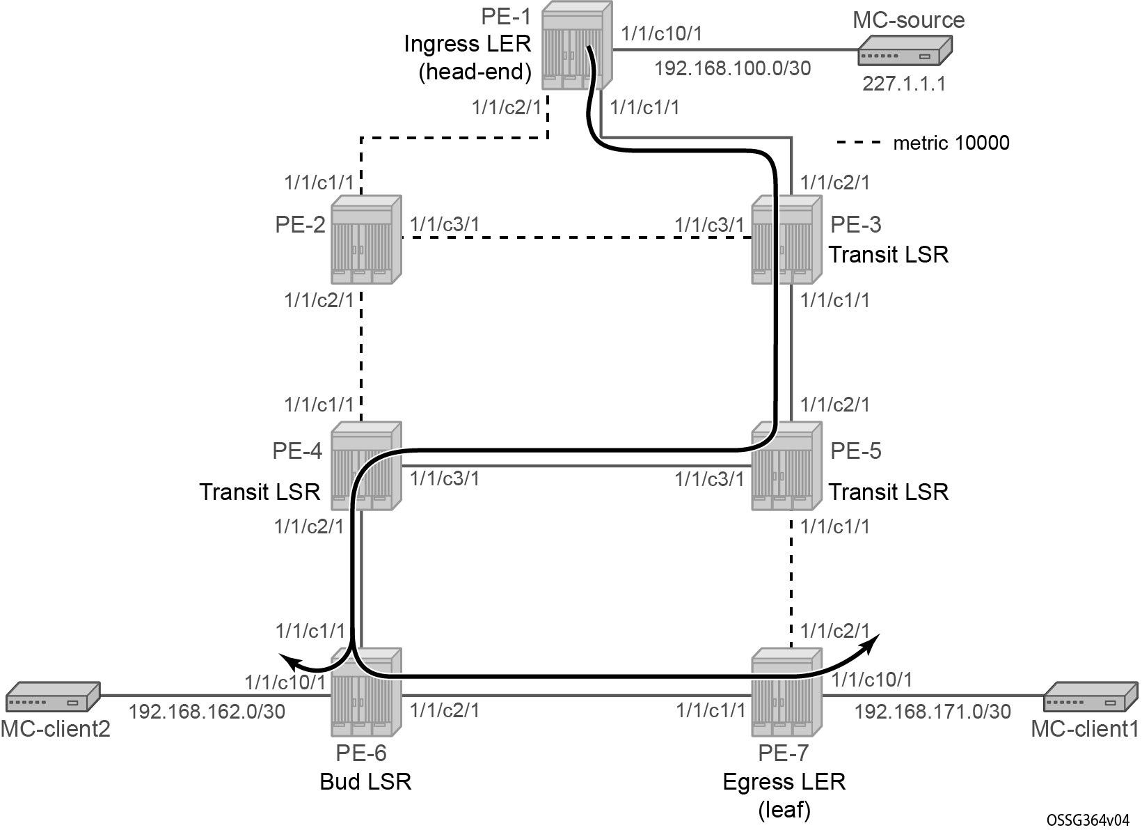
Influence IGP metric
The IGP metric is increased on all links pointing to/from PE-2 and on the link between PE-5 and PE-7.
# on PE-1:
configure
    router Base
        ospf 0
            area 0.0.0.0
                interface "int-PE-1-PE-2"
                    metric 10000
# on PE-2:
configure
    router Base
        ospf 0
            area 0.0.0.0
                interface "int-PE-2-PE-1"
                    metric 10000
                exit
                interface "int-PE-2-PE-3"
                    metric 10000
                exit
                interface "int-PE-2-PE-4"
                    metric 10000
                exit
# on PE-3:
configure
    router Base
        ospf 0
            area 0.0.0.0
                interface "int-PE-3-PE-2"
                    metric 10000
# on PE-4:
configure
    router Base
        ospf 0
            area 0.0.0.0
                interface "int-PE-4-PE-2"
                    metric 10000
# on PE-5:
configure
    router Base
        ospf 0
            area 0.0.0.0
                interface "int-PE-5-PE-7"
                    metric 10000
# on PE-7:
configure
    router Base
        ospf 0
            area 0.0.0.0
                interface "int-PE-7-PE-5"
                    metric 10000
The existing P2MP LSP LSP-p2mp-1 does not take into account these new constraints. The two S2L paths (one empty toward PE-6 and another empty toward PE-7) are calculated using the default OSPF metric. To trigger MPLS to recompute the S2L paths, configure a p2mp-resignal-timer on the head-end node inside the global MPLS context. Each time this timer expires (in the example, every 60 minutes), MPLS triggers CSPF to recompute the whole set of S2L paths of all active P2MP instances. MPLS performs a global Make-Before-Break (MBB) and moves each S2L sub-LSP in the instance into its new path using a new P2MP LSP ID if the global MBB is successful. show router mpls status gives an indication when the P2MP resignal timer will expire and which types of LSPs are set up on the node.
# on PE-1:
configure
    router Base
        mpls
            p2mp-resignal-timer 60        # in minutes
*A:PE-1# show router mpls status

===============================================================================
MPLS Status
===============================================================================
Admin Status              : Up
Oper(V4) State            : Up          Oper(V6) State            : Down
IPv4 Oper Down Reason     : n/a
IPv6 Oper Down Reason     : ipv6TeRtrDown
FRR Object                : Enabled     Resignal Timer            : Disabled
Hold Timer                : 1 seconds   Next Resignal             : N/A
Srlg Frr                  : Disabled    Srlg Frr Strict           : Disabled
Admin Group Frr           : Disabled
Dynamic Bypass            : Enabled     User Srlg Database        : Disabled
BypassResignalTimer       : Disabled    BypassNextResignal        : N/A
LeastFill Min Thd         : 5 percent   LeastFill Reopti Thd      : 10 percent
Local TTL Prop            : Enabled     Transit TTL Prop          : Enabled
P2mp TTL Prop             : Enabled
AB Sample Multiplier      : 1           AB Adjust Multiplier      : 288
Exp Backoff Retry         : Disabled    CSPF On Loose Hop         : Disabled
Lsp Init RetryTimeout     : 30 seconds  MBB Pref Current Hops     : Disabled
Logger Event Bundling     : Disabled
Retry on IGP Overload     : Disabled    Resignal on IGP Overload  : Disabled
Resignal on IGP Event     : Disabled
StrictEroNhopDirectRes    : Disabled

P2mp Resignal Timer       : 60 minutes  P2mp Next Resignal        : 59 minutes
Sec FastRetryTimer        : Disabled    Static LSP FR Timer       : 30 seconds
P2P Max Bypass Association: 1000
Max Bypass PLR Association: 16
P2PActPathFastRetry       : Disabled    P2MP S2L Fast Retry       : Disabled
In Maintenance Mode       : No
MplsTp                    : Disabled
Next Available Lsp Index  : 2
Entropy Label RSVP-TE     : Enabled     Entropy Label SR-TE       : Enabled
PCE Report RSVP-TE        : Disabled    PCE Report SR-TE          : Disabled
PCE Init LSP              : Disabled
PCC Oper Status RSVP-TE   : Down        PCE Oper Status RSVP-TE   : Down
PCC Oper Status SR-TE     : Down        PCE Oper Status SR-TE     : Down
SR-TE Resignal Timer      : Disabled    SR-TE Next Resignal       : N/A
SR-TE Resig on IGP Event  : Disabled    SR-TE Resig on IGP Overlo*: Disabled
LSP BSID Block            : N/A
LSP History               : Disabled
LSP Self Ping Timeout     : 300 seconds LSP Self Ping Interval    : 1 seconds
RSVP-TE LSP Self Ping     : Disabled    Self Ping Timeout Action  : retry
RSVP-TE Tunnel Table Pref : 7           SR-TE Tunnel Table Pref   : 8

===============================================================================
MPLS LSP Count
===============================================================================
                          Originate         Transit           Terminate
-------------------------------------------------------------------------------
Static LSPs               0                 0                 0
Dynamic LSPs              2                 0                 0
P2P LSPs                  0                 N/A               N/A
Detour LSPs               0                 0                 0
P2MP S2Ls                 2                 0                 0
MPLS-TP LSPs              0                 0                 0
Mesh-P2P LSPs             0                 N/A               N/A
One Hop-P2P LSPs          0                 N/A               N/A
SR-TE LSPs                0                 N/A               N/A
Mesh-P2P SR-TE LSPs       0                 N/A               N/A
One Hop-P2P SR-TE LSPs    0                 N/A               N/A
PCE Init SR-TE LSPs       0                 N/A               N/A
On-Demand SR-TE LSPs      0                 N/A               N/A
===============================================================================
As an alternative, users can also perform a manual resignal of a P2MP instance on the head-end node using the following tools command:
# on PE-1:
tools
    perform
        router Base
            mpls
                resignal p2mp-lsp "LSP-p2mp-1" p2mp-instance "p-LSP-p2mp-1"
# on PE-1:
tools
    perform
        router Base
            mpls
                resignal p2mp-delay 0
P2MP LSP p-to-mp-1 with metric change shows the resignaled S2L paths. Node PE-6 is now a bud LSR node (instead of egress LER before).
The following command shows the new actual and computed hops in the resignaled S2L path to PE-7:
*A:PE-1# show router mpls p2mp-lsp "LSP-p2mp-1" p2mp-instance "p-LSP-p2mp-1" s2l empty to 192.0.2.7 detail

===============================================================================
MPLS LSP LSP-p2mp-1 S2L empty (Detail)
===============================================================================
Legend :
    @ - Detour Available                          # - Detour In Use
    b - Bandwidth Protected                       n - Node Protected
    S - Strict                                    L - Loose
    A - ABR
    s - Soft Preemption
===============================================================================
LSP Name         : LSP-p2mp-1
S2L LSP ID       : 52738
P2MP ID          : 0                       S2L Grp Id        : 1
Admin State      : Up                      Oper State        : Up
S2L State:       : Active                                    :
S2L Name         : empty
To               : 192.0.2.7
S2L Admin        : Up                      S2L Oper          : Up
OutInterface     : 1/1/c1/1:1000           Out Label         : 524283
S2L Up Time      : 0d 00:21:04             S2L Dn Time       : 0d 00:00:00
RetryAttempt     : 0                       NextRetryIn       : 0 sec
S2L Trans        : 2                       CSPF Queries      : 2
Failure Code     : noError                 Failure Node      : n/a
Inter-area       : False
ExplicitHops     :
    No Hops Specified
Actual Hops      :
    192.168.13.1(192.0.2.1) @                    Record Label        : N/A
 -> 192.168.13.2(192.0.2.3) @                    Record Label        : 524283
 -> 192.168.35.2(192.0.2.5) @                    Record Label        : 524283
 -> 192.168.45.1(192.0.2.4) @                    Record Label        : 524283
 -> 192.168.46.2(192.0.2.6) @                    Record Label        : 524284
 -> 192.168.67.2(192.0.2.7)                      Record Label        : 524284
ComputedHops     :
    192.168.13.1(S)
 -> 192.168.13.2(S)
 -> 192.168.35.2(S)
 -> 192.168.45.1(S)
 -> 192.168.46.2(S)
 -> 192.168.67.2(S)
LastResignal     : n/a
===============================================================================
The following command shows the new actual and computed hops in the resignaled S2L path to PE-6:
*A:PE-1# show router mpls p2mp-lsp "LSP-p2mp-1" p2mp-instance "p-LSP-p2mp-1" s2l empty to 192.0.2.6 detail

===============================================================================
MPLS LSP LSP-p2mp-1 S2L empty (Detail)
===============================================================================
Legend :
    @ - Detour Available                          # - Detour In Use
    b - Bandwidth Protected                       n - Node Protected
    S - Strict                                    L - Loose
    A - ABR
    s - Soft Preemption
===============================================================================
LSP Name         : LSP-p2mp-1
S2L LSP ID       : 52738
P2MP ID          : 0                       S2L Grp Id        : 2
Admin State      : Up                      Oper State        : Up
S2L State:       : Active                                    :
S2L Name         : empty
To               : 192.0.2.6
S2L Admin        : Up                      S2L Oper          : Up
OutInterface     : 1/1/c1/1:1000           Out Label         : 524283
S2L Up Time      : 0d 00:21:04             S2L Dn Time       : 0d 00:00:00
RetryAttempt     : 0                       NextRetryIn       : 0 sec
S2L Trans        : 2                       CSPF Queries      : 2
Failure Code     : noError                 Failure Node      : n/a
Inter-area       : False
ExplicitHops     :
    No Hops Specified
Actual Hops      :
    192.168.13.1(192.0.2.1) @                    Record Label        : N/A
 -> 192.168.13.2(192.0.2.3) @                    Record Label        : 524283
 -> 192.168.35.2(192.0.2.5) @                    Record Label        : 524283
 -> 192.168.45.1(192.0.2.4) @                    Record Label        : 524283
 -> 192.168.46.2(192.0.2.6)                      Record Label        : 524284
ComputedHops     :
    192.168.13.1(S)
 -> 192.168.13.2(S)
 -> 192.168.35.2(S)
 -> 192.168.45.1(S)
 -> 192.168.46.2(S)
LastResignal     : n/a
===============================================================================
An oam p2mp-lsp-trace command toward PE-7 now sets the E flag on PE-6 because PE-6 acts also as an egress LER node.
*A:PE-1# oam p2mp-lsp-trace "LSP-p2mp-1" p2mp-instance "p-LSP-p2mp-1" s2l-dest-address 192.0.2.7 detail
P2MP LSP LSP-p2mp-1: 132 bytes MPLS payload
P2MP Instance p-LSP-p2mp-1, S2L Egress 192.0.2.7

  1  192.0.2.3  rtt=2.06 ms rc=8(DSRtrMatchLabel)
     DS 1: ipaddr=192.168.35.2 ifaddr=192.168.35.2 iftype=ipv4Numbered MRU=8982 label=524283 proto=4(RSVP-TE) B/E flags:0/0
  2  192.0.2.5  rtt=3.29 ms rc=8(DSRtrMatchLabel)
     DS 1: ipaddr=192.168.45.1 ifaddr=192.168.45.1 iftype=ipv4Numbered MRU=8982 label=524283 proto=4(RSVP-TE) B/E flags:0/0
  3  192.0.2.4  rtt=3.57 ms rc=8(DSRtrMatchLabel)
     DS 1: ipaddr=192.168.46.2 ifaddr=192.168.46.2 iftype=ipv4Numbered MRU=8982 label=524284 proto=4(RSVP-TE) B/E flags:0/0
  4  192.0.2.6  rtt=4.83 ms rc=8(DSRtrMatchLabel)
     DS 1: ipaddr=192.168.67.2 ifaddr=192.168.67.2 iftype=ipv4Numbered MRU=8982 label=524284 proto=4(RSVP-TE) B/E flags:0/1
  5  192.0.2.7  rtt=5.75 ms rc=3(EgressRtr)
In the next step, the S2L path toward PE-7 is changed from an empty path to a strict direct MPLS path (path-strict-to-PE-7). In that way, OSPF is not calculating the shortest path to the leaf node anymore.
# on PE-1:
configure
    router Base
        mpls
            path "path-strict-to-PE-7"
                hop 10 192.168.13.2 strict
                hop 20 192.168.35.2 strict
                hop 30 192.168.57.2 strict
                no shutdown
            exit
Before applying this new S2L path to the existing P2MP LSP (LSP-p2mp-1), the existing S2L path toward PE-7 must be removed.
# on PE-1:
configure
    router Base
        mpls
            lsp "LSP-p2mp-1"
                primary-p2mp-instance "p-LSP-p2mp-1"
                    s2l-path "empty" to 192.0.2.7 shutdown
                    no s2l-path "empty" to 192.0.2.7
                    s2l-path "path-strict-to-PE-7" to 192.0.2.7
                    exit
                exit
As a consequence of this, only the S2L group ID changes while S2L LSP ID remains the same. P2MP LSP LSP-p2mp-1 with strict S2L path toward PE-7 shows the P2MP LSP LSP-p2mp-1 with strict S2L path to leaf PE-7.
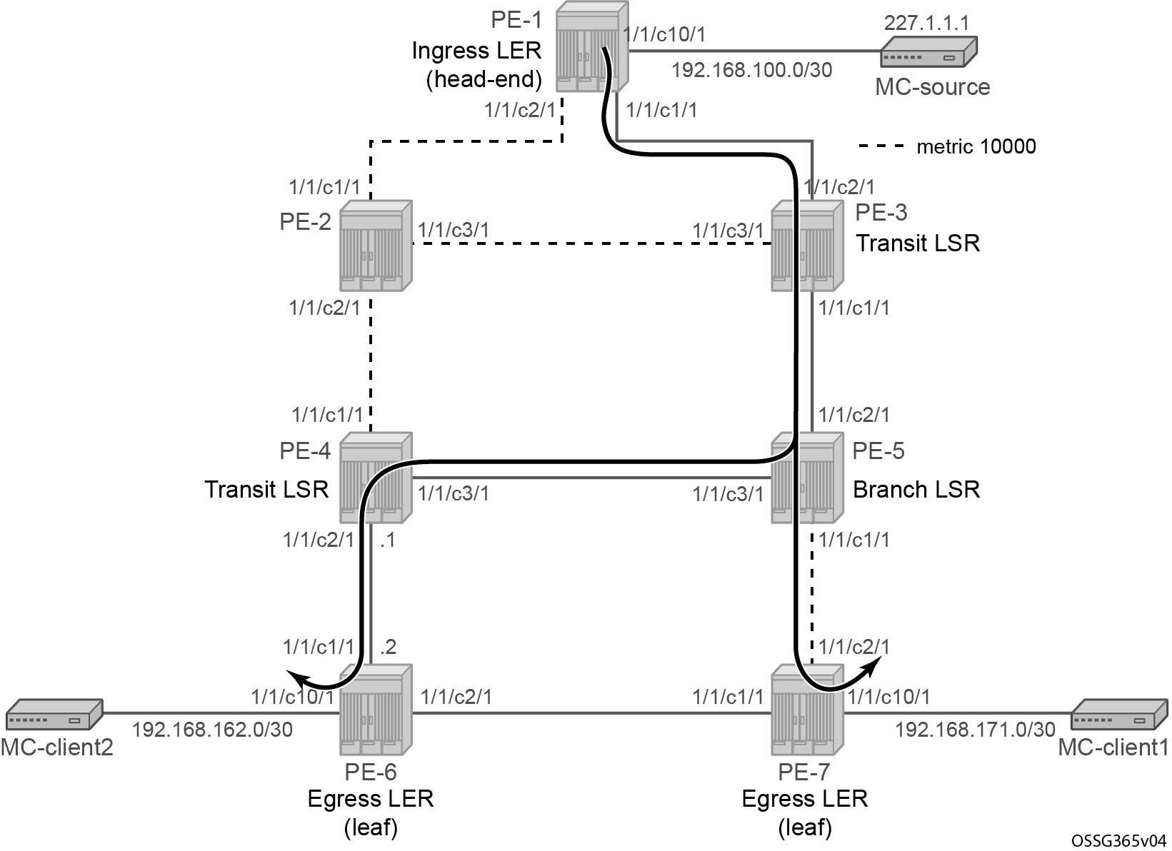
S2L paths can be verified according to P2MP LSP LSP-p2mp-1 with strict S2L path toward PE-7. PE-5 is now a branch LSR node (instead of a transit LSR before).
*A:PE-1# show router mpls p2mp-lsp "LSP-p2mp-1" p2mp-instance "p-LSP-p2mp-1" s2l path-strict-to-PE-7 to 192.0.2.7 detail

===============================================================================
MPLS LSP LSP-p2mp-1 S2L path-strict-to-PE-7 (Detail)
===============================================================================
Legend :
    @ - Detour Available                          # - Detour In Use
    b - Bandwidth Protected                       n - Node Protected
    S - Strict                                    L - Loose
    A - ABR
    s - Soft Preemption
===============================================================================
LSP Name         : LSP-p2mp-1
S2L LSP ID       : 52738
P2MP ID          : 0                       S2L Grp Id        : 3
Admin State      : Up                      Oper State        : Up
S2L State:       : Active                                    :
S2L Name         : path-strict-to-PE-7
To               : 192.0.2.7
S2L Admin        : Up                      S2L Oper          : Up
OutInterface     : 1/1/c1/1:1000           Out Label         : 524283
S2L Up Time      : 0d 00:01:12             S2L Dn Time       : 0d 00:00:00
RetryAttempt     : 0                       NextRetryIn       : 0 sec
S2L Trans        : 1                       CSPF Queries      : 1
Failure Code     : noError                 Failure Node      : n/a
Inter-area       : False
ExplicitHops     :
                  192.168.13.2(S)
               -> 192.168.35.2(S)
               -> 192.168.57.2(S)
Actual Hops      :
    192.168.13.1(192.0.2.1) @                    Record Label        : N/A
 -> 192.168.13.2(192.0.2.3) @                    Record Label        : 524283
 -> 192.168.35.2(192.0.2.5) @                    Record Label        : 524283
 -> 192.168.57.2(192.0.2.7)                      Record Label        : 524287
ComputedHops     :
    192.168.13.1(S)
 -> 192.168.13.2(S)
 -> 192.168.35.2(S)
 -> 192.168.57.2(S)
LastResignal     : n/a
===============================================================================
An oam p2mp-lsp-trace command toward PE-7 now sets the B flag on PE-5 because PE-5 acts as a branch LSR now.
*A:PE-1# oam p2mp-lsp-trace "LSP-p2mp-1" p2mp-instance "p-LSP-p2mp-1" s2l-dest-address 192.0.2.7 detail
P2MP LSP LSP-p2mp-1: 132 bytes MPLS payload
P2MP Instance p-LSP-p2mp-1, S2L Egress 192.0.2.7

  1  192.0.2.3  rtt=1.98 ms rc=8(DSRtrMatchLabel)
     DS 1: ipaddr=192.168.35.2 ifaddr=192.168.35.2 iftype=ipv4Numbered MRU=8982 label=524283 proto=4(RSVP-TE) B/E flags:0/0
  2  192.0.2.5  rtt=3.12 ms rc=8(DSRtrMatchLabel)
     DS 1: ipaddr=192.168.57.2 ifaddr=192.168.57.2 iftype=ipv4Numbered MRU=8982 label=524287 proto=4(RSVP-TE) B/E flags:1/0
  3  192.0.2.7  rtt=4.41 ms rc=3(EgressRtr)
Intelligent remerge
Intelligent remerge protects users from receiving duplicate multicast traffic during convergence. It also protects against duplicate traffic in case of badly designed S2L paths. Three cases are described for which intelligent remerge is implemented.
Intelligent remerge case 1 - Badly designed S2L paths
In this example, the paths of two different S2Ls of the same P2MP LSP instance have ingress label maps (ILMs) on different ports but go out on the same Next-Hop Label Forwarding Entry (NHLFE).
Intelligent remerge, case 1 shows P2MP LSP LSP-p2mp-2 with two incoming S2L paths at PE-5.
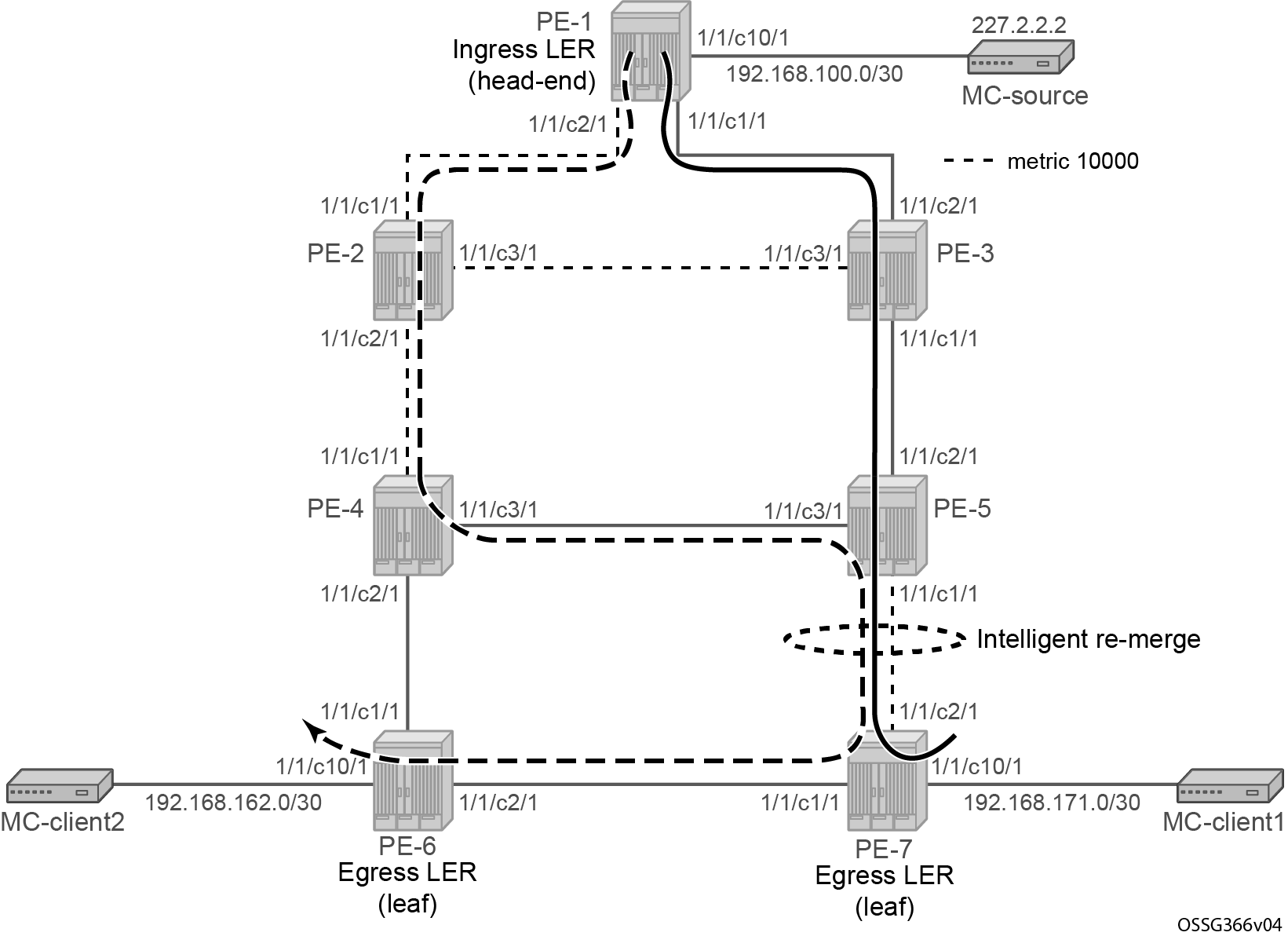
On the head-end node (PE-1), P2MP LSP LSP-p2mp-2 is created with two strict direct MPLS paths (path-strict-to-PE-7 and path-strict-to-PE-6), as follows. Intelligent remerge is performed at node PE-5.
# on PE-1:
configure
    router Base
        mpls
            path "path-strict-to-PE-7"
                hop 10 192.168.13.2 strict
                hop 20 192.168.35.2 strict
                hop 30 192.168.57.2 strict
                no shutdown
            exit
            path "path-strict-to-PE-6"
                hop 10 192.168.12.2 strict
                hop 20 192.168.24.2 strict
                hop 30 192.168.45.2 strict
                hop 40 192.168.57.2 strict
                hop 50 192.168.67.1 strict
                no shutdown
            exit
            lsp "LSP-p2mp-2" p2mp-lsp
                from 192.0.2.1
                primary-p2mp-instance "p-LSP-p2mp-2"
                    s2l-path "path-strict-to-PE-7" to 192.0.2.7
                    exit
                    s2l-path "path-strict-to-PE-6" to 192.0.2.6
                    exit
                exit
                no shutdown
            exit
            no shutdown
*A:PE-1# show router mpls p2mp-lsp "LSP-p2mp-2" p2mp-instance "p-LSP-p2mp-2"

===============================================================================
MPLS P2MP Instance (Originating)
===============================================================================
-------------------------------------------------------------------------------
Type : Originating
-------------------------------------------------------------------------------
LSP Name    : LSP-p2mp-2
P2MP ID         : 0                         LSP Tunnel ID        : 2
Adm State       : Up                        Oper State           : Up

P2MPInstance    : p-LSP-p2mp-2
                                            P2MP-Inst-type       : Primary
P2MP Inst Id    : 2                         P2MP Lsp Id          : 55808
Inst Admin      : Up                        Inst Oper            : Up
Inst Up Time    : 0d 00:00:03               Inst Dn Time         : 0d 00:00:00
Hop Limit       : 255                       Adaptive             : Enabled
Record Route    : Record                    Record Label         : Record
Setup Priority  : 7                         Hold Priority        : 0
Include Grps    :                           Exclude Grps         :
None                                           None
Bandwidth       : No Reservation            Oper Bw              : 0 Mbps
S2L-Name        : path-strict-to-PE-7
                                            To                   : 192.0.2.7
S2L Admin       : Up                        S2L Oper             : Up
S2L-Name        : path-strict-to-PE-6
                                            To                   : 192.0.2.6
S2L Admin       : Up                        S2L Oper             : Up
-------------------------------------------------------------------------------
P2MP instances : 1
===============================================================================
To verify that node PE-5 is not sending duplicate multicast traffic downstream toward PE-7 while it receives two incoming multicast streams, a new tunnel interface and a new static <S,G> IGMP join are configured on head-end node (PE-1) and leaf nodes (PE-6 and PE-7). Also on the leaf nodes, an extension to the existing multicast information policy is needed. The configuration is as follows:
# on PE-1:
configure
    router Base
        pim
            tunnel-interface rsvp-p2mp "LSP-p2mp-2"
        exit
        igmp
            tunnel-interface rsvp-p2mp "LSP-p2mp-2"
                static
                    group 227.2.2.2
                        source 192.168.100.2
                    exit
                exit
            exit
# on PE-6:
configure
    router Base
        pim
            tunnel-interface rsvp-p2mp "LSP-p2mp-2" sender 192.0.2.1
        exit
        igmp
            interface "int-PE-6-MC-client2"
                static
                    group 227.2.2.2
                        source 192.168.100.2
                    exit
                exit
            exit
        exit
    exit
    mcast-management
        multicast-info-policy "p2mp-pol" create
            bundle "bundle2" create
                primary-tunnel-interface rsvp-p2mp "LSP-p2mp-2" sender 192.0.2.1
                    channel "227.2.2.2" "227.2.2.2" create
                    exit
                exit
            exit
# on PE-7:
configure
    router Base
        pim
            tunnel-interface rsvp-p2mp "LSP-p2mp-2" sender 192.0.2.1
        exit
        igmp
            interface int-PE-7-MC-client1
                static
                    group 227.2.2.2
                        source 192.168.100.2
                    exit
                exit
            exit
        exit
    exit
    mcast-management
        multicast-info-policy "p2mp-pol" create
            bundle "bundle2" create
                primary-tunnel-interface rsvp-p2mp "LSP-p2mp-2" sender 192.0.2.1
                    channel "227.2.2.2" "227.2.2.2" create
                    exit
                exit
            exit
For verification of incoming/outgoing multicast traffic at node PE-5, the monitor command is used.
*A:PE-5# monitor port 1/1/c1/1 1/1/c2/1 1/1/c3/1 rate interval 3 repeat 10

===============================================================================
Monitor statistics for Ports
===============================================================================
                                                   Input                 Output
-------------------------------------------------------------------------------
-------------------------------------------------------------------------------

---snip---
-------------------------------------------------------------------------------
At time t = 6 sec (Mode: Rate)
-------------------------------------------------------------------------------
Port 1/1/c1/1
-------------------------------------------------------------------------------
Octets                                                51                1239733
Packets                                                0                    881
Errors                                                 0                      0
Bits                                                 408                9917864
Utilization (% of port capacity)                   ~0.00                   0.01

Port 1/1/c2/1
-------------------------------------------------------------------------------
Octets                                           1239669                     73
Packets                                              881                      1
Errors                                                 0                      0
Bits                                             9917352                    584
Utilization (% of port capacity)                    0.01                  ~0.00

Port 1/1/c3/1
-------------------------------------------------------------------------------
Octets                                           1239598                     21
Packets                                              881                      0
Errors                                                 0                      0
Bits                                             9916784                    168
Utilization (% of port capacity)                    0.01                  ~0.00

-------------------------------------------------------------------------------
---snip---
Two incoming multicast streams are seen at PE-5 node (port 1/1/c2/1 and port 1/1/c3/1) and only one outgoing multicast stream (port 1/1/c1/1) is sent. No traffic duplication is seen.
Intelligent remerge case 2 - Make-before-break after graceful shutdown
Intelligent remerge, case 2 shows two paths of the same S2L that have Ingress Label Map (ILM) entries on different incoming ports and go out on the same NHLFE. This is the case during a make-before-break (MBB) operation on an S2L path after a graceful shutdown or global revertive. This is only a temporary situation until the original path is torn down.
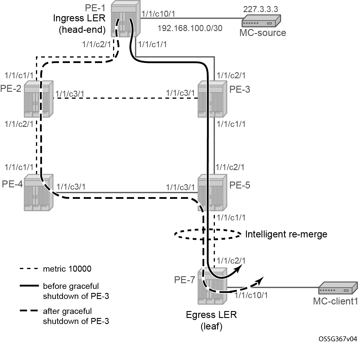
For this test, only multicast client MC-client1 is used (the one connected to leaf node PE-7). On nodes PE-4 and PE-7, the port to PE-6 is disabled to isolate PE-6. On the head-end node PE-1, a new P2MP LSP LSP-p2mp-3 is created with an empty MPLS path and with CSPF enabled. The metric type is TE to ensure that CSPF uses the TE metric instead of the IGP metric. In this case, the TE metric has the same value on all MPLS interfaces and the path has the hops PE-1, PE-3, PE-5, and PE-7. Also in this case, intelligent remerge is performed at node PE-5.
# on PE-1:
configure
    router Base
        mpls
            path "empty"
                no shutdown
            exit
            lsp "LSP-p2mp-3" p2mp-lsp
                from 192.0.2.1
                path-computation-method local-cspf
                metric-type te
                primary-p2mp-instance "p-LSP-p2mp-3"
                    s2l-path "empty" to 192.0.2.7
                    exit
                exit
                no shutdown
            exit
*A:PE-1# show router mpls p2mp-lsp "LSP-p2mp-3" p2mp-instance "p-LSP-p2mp-3" s2l "empty" to 192.0.2.7 detail

===============================================================================
MPLS LSP LSP-p2mp-3 S2L empty (Detail)
===============================================================================
Legend :
    @ - Detour Available                          # - Detour In Use
    b - Bandwidth Protected                       n - Node Protected
    S - Strict                                    L - Loose
    A - ABR
    s - Soft Preemption
===============================================================================
LSP Name         : LSP-p2mp-3
S2L LSP ID       : 26624
P2MP ID          : 0                       S2L Grp Id        : 1
Admin State      : Up                      Oper State        : Up
S2L State:       : Active                                    :
S2L Name         : empty
To               : 192.0.2.7
S2L Admin        : Up                      S2L Oper          : Up
OutInterface     : 1/1/c1/1:1000           Out Label         : 524286
S2L Up Time      : 0d 00:00:15             S2L Dn Time       : 0d 00:00:00
RetryAttempt     : 0                       NextRetryIn       : 0 sec
S2L Trans        : 1                       CSPF Queries      : 1
Failure Code     : noError                 Failure Node      : n/a
Inter-area       : False
ExplicitHops     :
    No Hops Specified
Actual Hops      :
    192.168.13.1(192.0.2.1)                      Record Label        : N/A
 -> 192.168.13.2(192.0.2.3)                      Record Label        : 524286
 -> 192.168.35.2(192.0.2.5)                      Record Label        : 524282
 -> 192.168.57.2(192.0.2.7)                      Record Label        : 524282
ComputedHops     :
    192.168.13.1(S)
 -> 192.168.13.2(S)
 -> 192.168.35.2(S)
 -> 192.168.57.2(S)
LastResignal     : n/a
===============================================================================
In a normal situation, the P2MP LSP follows the nodes PE-1, PE-3, PE-5, and PE-7. This can be verified with multicast traffic. Therefore, a new tunnel interface and a new static <S,G> IGMP join are configured on head-end node PE-1 and leaf node PE-7. On the leaf node, an extension to the existing multicast information policy is needed. The configuration is as follows:
# on PE-1:
configure
    router Base
        pim
            tunnel-interface rsvp-p2mp "LSP-p2mp-3"
        exit
        igmp
            tunnel-interface rsvp-p2mp "LSP-p2mp-3"
                no shutdown
                static
                    group 227.3.3.3
                        source 192.168.100.2
                    exit
                exit
            exit
# on PE-7:
configure
    router Base
        pim
            tunnel-interface rsvp-p2mp "LSP-p2mp-3" sender 192.0.2.1
        exit
        igmp
            interface "int-PE-7-MC-client1"
                static
                    group 227.3.3.3
                        source 192.168.100.2
                    exit
                exit
            exit
        exit
    exit
    mcast-management
        multicast-info-policy "p2mp-pol" create
            bundle "bundle3" create
                primary-tunnel-interface rsvp-p2mp "LSP-p2mp-3" sender 192.0.2.1
                channel "227.3.3.3" "227.3.3.3" create
                exit
            exit
        exit
The traffic on PE-5 is monitored. Under normal circumstances, the ingress port is 1/1/c2/1 and the egress port is 1/1/c1/1.
*A:PE-5# monitor port 1/1/c1/1 1/1/c2/1 1/1/c3/1 rate interval 3

===============================================================================
Monitor statistics for Ports
===============================================================================
                                                   Input                 Output
-------------------------------------------------------------------------------
-------------------------------------------------------------------------------

---snip---
-------------------------------------------------------------------------------
At time t = 6 sec (Mode: Rate)
-------------------------------------------------------------------------------
Port 1/1/c1/1
-------------------------------------------------------------------------------
Octets                                                51                1239561
Packets                                                0                    881
Errors                                                 0                      0
Bits                                                 408                9916488
Utilization (% of port capacity)                   ~0.00                   0.01

Port 1/1/c2/1
-------------------------------------------------------------------------------
Octets                                           1239061                     21
Packets                                              880                      0
Errors                                                 0                      0
Bits                                             9912488                    168
Utilization (% of port capacity)                    0.01                  ~0.00

Port 1/1/c3/1
-------------------------------------------------------------------------------
Octets                                                21                     21
Packets                                                0                      0
Errors                                                 0                      0
Bits                                                 168                    168
Utilization (% of port capacity)                   ~0.00                  ~0.00

-------------------------------------------------------------------------------
An RSVP graceful shutdown is performed on node PE-3, as follows:
# on PE-3:
configure
    router Base
        rsvp
            graceful-shutdown
The graceful shutdown on PE-3 triggers a global revertive on head-end node PE-1. A new MPLS path is calculated (see the dashed line in Intelligent remerge, case 2). For a few seconds or even less than a second, the old path and new path are active (two incoming multicast streams on node PE-5). Node PE-5 is doing intelligent remerge, not sending duplicate multicast traffic downstream toward PE-7:
*A:PE-5# monitor port 1/1/c1/1 1/1/c2/1 1/1/c31 rate interval 3 repeat 20

===============================================================================
Monitor statistics for Ports
===============================================================================
                                                   Input                 Output
-------------------------------------------------------------------------------
---snip---

-------------------------------------------------------------------------------
At time t = 30 sec (Mode: Rate)
-------------------------------------------------------------------------------
Port 1/1/c1/1
-------------------------------------------------------------------------------
Octets                                               131                1239824
Packets                                                1                    882
Errors                                                 0                      0
Bits                                                1048                9918592
Utilization (% of port capacity)                   ~0.00                   0.01

Port 1/1/c2/1
-------------------------------------------------------------------------------
Octets                                           1239552                     43
Packets                                              881                      1
Errors                                                 0                      0
Bits                                             9916416                    344
Utilization (% of port capacity)                    0.01                  ~0.00

Port 1/1/c3/1
-------------------------------------------------------------------------------
Octets                                             10124                    166
Packets                                                8                      1
Errors                                                 0                      0
Bits                                               80992                   1328
Utilization (% of port capacity)                   ~0.00                  ~0.00

---snip---
The granularity of the monitoring command is 3 seconds. The graceful shutdown takes less than 3 seconds. However, it is clear that the number of outgoing packets on port 1/1/c1/1 equals the number of incoming packets on port 1/1/c2/1. A number of these incoming packets also arrived on port 1/1/c3/1, but no duplicate packets were sent on the outgoing port. No traffic duplication is seen.
<continued>
-------------------------------------------------------------------------------
At time t = 33 sec (Mode: Rate)
-------------------------------------------------------------------------------
Port 1/1/c1/1
-------------------------------------------------------------------------------
Octets                                                63                1238788
Packets                                                0                    880
Errors                                                 0                      0
Bits                                                 504                9910304
Utilization (% of port capacity)                   ~0.00                   0.01

Port 1/1/c2/1
-------------------------------------------------------------------------------
Octets                                            291673                    131
Packets                                              208                      1
Errors                                                 0                      0
Bits                                             2333384                   1048
Utilization (% of port capacity)                   ~0.00                  ~0.00

Port 1/1/c3/1
-------------------------------------------------------------------------------
Octets                                           1239678                    225
Packets                                              881                      1
Errors                                                 0                      0
Bits                                             9917424                   1800
Utilization (% of port capacity)                    0.01                  ~0.00

-------------------------------------------------------------------------------
---snip---
Eventually, port 1/1/c3/1 takes over all traffic.
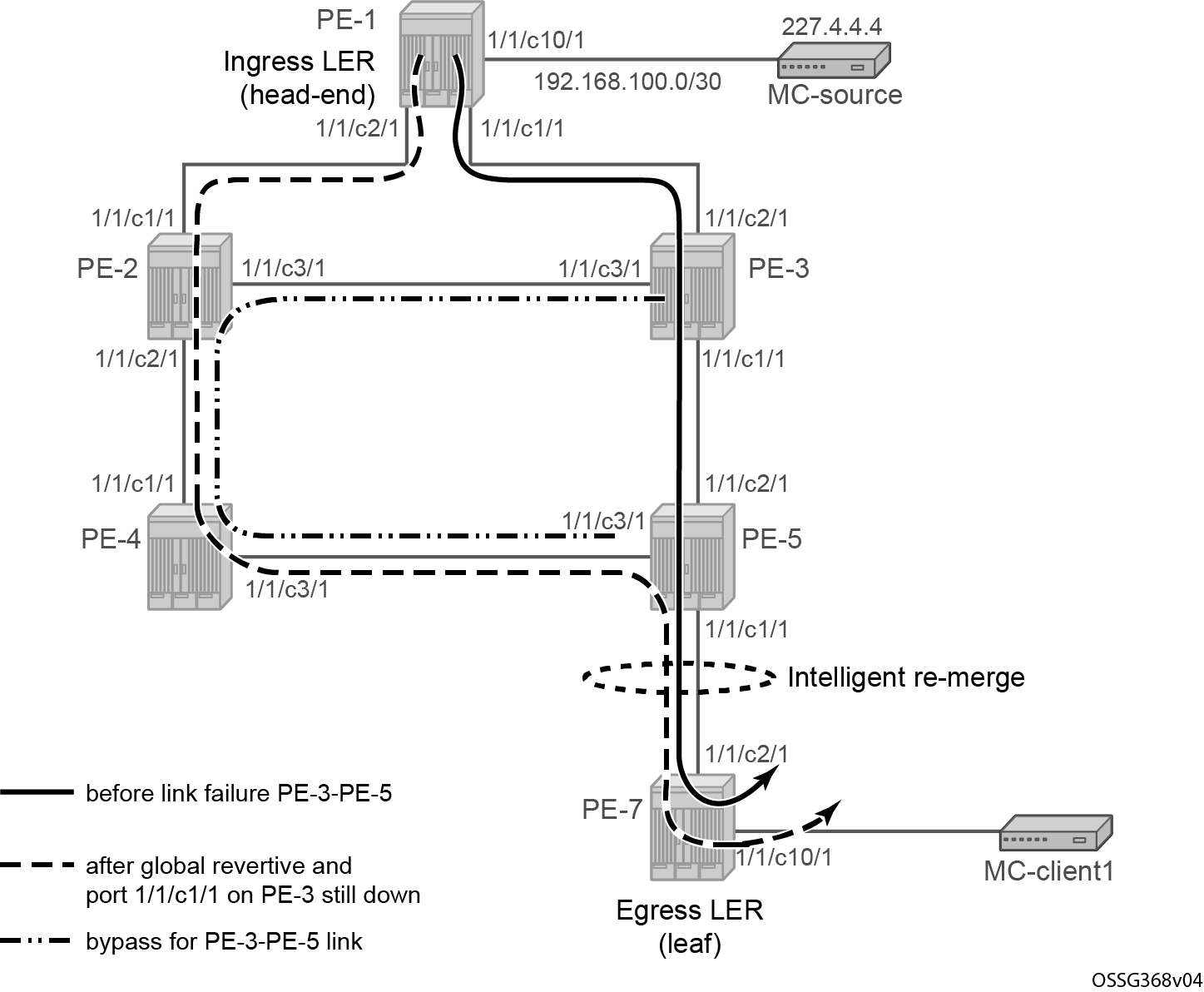
Intelligent remerge case 3 - Bypass and new global revertive path
When a bypass is active on the S2L path and the new global revertive path of the same S2L arrives on the same incoming interface as the original path (interface flapped) at the FRR merge point node, the node performs intelligent remerge. The implementation recognizes this specific case and signals a different label from the original S2L path coming on that same interface.
Intelligent remerge, case 3 shows the initial S2L path before the link failure (solid line), the bypass path to protect the link between PE-3 and PE-5, and the new global revertive path of the S2L (dotted line). Both the bypass path and the global revertive path share the links between PE-2 and PE-4 and between PE-4 and PE-5.
For this test, all the non-default OSPF metrics are removed from the interfaces on all the PEs; on PE-1, as follows:
# on PE-1:
configure
    router Base
        ospf 0
            area 0.0.0.0
                interface "int-PE-1-PE-2"
                    no metric
Only one MC-client is used (MC-client1 connected to leaf node PE-7). On nodes PE-4 and PE-7, the port toward PE-6 is disabled to isolate PE-6. On the head-end node PE-1, a new P2MP LSP "LSP-p2mp-4" is created with an empty MPLS path and FRR enabled. Also in this case, intelligent remerge is performed at node PE-5.
# on PE-1:
configure
    router Base
        mpls
            path "empty"
                no shutdown
            exit
            lsp "LSP-p2mp-4" p2mp-lsp
                from 192.0.2.1
                path-computation-method local-cspf
                fast-reroute facility
                    no node-protect
                exit
                primary-p2mp-instance "p-LSP-p2mp-4"
                    s2l-path "empty" to 192.0.2.7
                    exit
                exit
                no shutdown
            exit
            no shutdown
*A:PE-1# show router mpls p2mp-lsp "LSP-p2mp-4" p2mp-instance "p-LSP-p2mp-4" s2l empty to 192.0.2.7 detail

===============================================================================
MPLS LSP LSP-p2mp-4 S2L empty (Detail)
===============================================================================
Legend :
    @ - Detour Available                          # - Detour In Use
    b - Bandwidth Protected                       n - Node Protected
    S - Strict                                    L - Loose
    A - ABR
    s - Soft Preemption
===============================================================================
LSP Name         : LSP-p2mp-4
S2L LSP ID       : 15872
P2MP ID          : 0                       S2L Grp Id        : 1
Admin State      : Up                      Oper State        : Up
S2L State:       : Active                                    :
S2L Name         : empty
To               : 192.0.2.7
S2L Admin        : Up                      S2L Oper          : Up
OutInterface     : 1/1/c1/1:1000           Out Label         : 524284
S2L Up Time      : 0d 00:01:04             S2L Dn Time       : 0d 00:00:00
RetryAttempt     : 0                       NextRetryIn       : 0 sec
S2L Trans        : 1                       CSPF Queries      : 1
Failure Code     : noError                 Failure Node      : n/a
Inter-area       : False
ExplicitHops     :
    No Hops Specified
Actual Hops      :
    192.168.13.1(192.0.2.1) @                    Record Label        : N/A
 -> 192.168.13.2(192.0.2.3) @                    Record Label        : 524284
 -> 192.168.35.2(192.0.2.5)                      Record Label        : 524284
 -> 192.168.57.2(192.0.2.7)                      Record Label        : 524286
ComputedHops     :
    192.168.13.1(S)
 -> 192.168.13.2(S)
 -> 192.168.35.2(S)
 -> 192.168.57.2(S)
LastResignal     : n/a
===============================================================================
In the normal situation, the P2MP LSP follows the nodes PE-1, PE-3, PE-5, and PE-7. This can be verified with multicast traffic. Therefore, a new tunnel interface and a new static <S,G> IGMP join are configured on head-end node PE-1 and leaf node PE-7. On the leaf node, an extension to the existing multicast information policy is needed. This is configured as follows:
# on PE-1:
configure
    router Base
        pim
            tunnel-interface rsvp-p2mp "LSP-p2mp-4"
        exit
        igmp
            tunnel-interface rsvp-p2mp "LSP-p2mp-4"
                no shutdown
                static
                    group 227.4.4.4
                        source 192.168.100.2
                    exit
                exit
            exit
        exit
# on PE-7:
configure
router Base
pim
tunnel-interface rsvp-p2mp "LSP-p2mp-4" sender 192.0.2.1
exit
igmp
interface "int-PE-7-MC-client1"
static
group 227.4.4.4
source 192.168.100.2
exit
exit
exit
exit
exit
mcast-management
multicast-info-policy "p2mp-pol" create
bundle "bundle4" create
primary-tunnel-interface rsvp-p2mp "LSP-p2mp-4" sender 192.0.2.1
channel "227.4.4.4" "227.4.4.4" create
exit
exit
exit
The initial path goes from PE-1 via PE-3 and PE-5 to PE-7. The following command emulates a link failure on the interface from PE-3 to PE-5:
# on PE-3:
configure
    port 1/1/c1/1
        shutdown
As a consequence of this, traffic flows from PE-1 to PE-3 and then over the bypass link from PE-3 via PE-2 and PE-4 to PE-5, as shown in Intelligent remerge, case 3. The following command shows the ‛#’ symbol for actual hop 192.168.13.2 and the failure code is tunnelLocallyRepaired:
*A:PE-1# show router mpls p2mp-lsp "LSP-p2mp-4" p2mp-instance "p-LSP-p2mp-4" s2l empty to 192.0.2.7 detail

===============================================================================
MPLS LSP LSP-p2mp-4 S2L empty (Detail)
===============================================================================
Legend :
    @ - Detour Available                          # - Detour In Use
    b - Bandwidth Protected                       n - Node Protected
    S - Strict                                    L - Loose
    A - ABR
    s - Soft Preemption
===============================================================================
LSP Name         : LSP-p2mp-4
S2L LSP ID       : 48640
P2MP ID          : 0                       S2L Grp Id        : 1
Admin State      : Up                      Oper State        : Up
S2L State:       : Active                                    :
S2L Name         : empty
To               : 192.0.2.7
S2L Admin        : Up                      S2L Oper          : Up
OutInterface     : 1/1/c1/1:1000           Out Label         : 524284
S2L Up Time      : 0d 00:01:45             S2L Dn Time       : 0d 00:00:00
RetryAttempt     : 0                       NextRetryIn       : 0 sec
S2L Trans        : 1                       CSPF Queries      : 2
Failure Code     : tunnelLocallyRepaired   Failure Node      : 192.0.2.3
Inter-area       : False
ExplicitHops     :
    No Hops Specified
Actual Hops      :
    192.168.13.1(192.0.2.1) @                    Record Label        : N/A
 -> 192.168.13.2(192.0.2.3) @ #                  Record Label        : 524284
 -> 192.168.35.2(192.0.2.5)                      Record Label        : 524284
 -> 192.168.57.2(192.0.2.7)                      Record Label        : 524286
ComputedHops     :
    192.168.13.1(S)
 -> 192.168.13.2(S)
 -> 192.168.35.2(S)
 -> 192.168.57.2(S)
LastResignal     : n/a
In Prog MBB :
 MBB Type        : GlobalRevert            NextRetryIn       : 7 sec
 Started At      : 02/11/2025 08:59:39     RetryAttempt      : 0
 FailureCode     : noError                 Failure Node      : n/a
===============================================================================
In the meantime, PE-3 triggers a global revertive action by sending a PathErr message toward the head-end node PE-1. After the global revert, the path goes from PE-1 via PE-2, PE-4, and PE-5 to PE-7.
*A:PE-1# show router mpls p2mp-lsp "LSP-p2mp-4" p2mp-instance "p-LSP-p2mp-4" s2l empty to 192.0.2.7 detail

===============================================================================
MPLS LSP LSP-p2mp-4 S2L empty (Detail)
===============================================================================
Legend :
    @ - Detour Available                          # - Detour In Use
    b - Bandwidth Protected                       n - Node Protected
    S - Strict                                    L - Loose
    A - ABR
    s - Soft Preemption
===============================================================================
LSP Name         : LSP-p2mp-4
S2L LSP ID       : 15872
P2MP ID          : 0                       S2L Grp Id        : 2
Admin State      : Up                      Oper State        : Up
S2L State:       : Active                                    :
S2L Name         : empty
To               : 192.0.2.7
S2L Admin        : Up                      S2L Oper          : Up
OutInterface     : 1/1/c2/1:1000           Out Label         : 524283
S2L Up Time      : 0d 00:03:36             S2L Dn Time       : 0d 00:00:00
RetryAttempt     : 0                       NextRetryIn       : 0 sec
S2L Trans        : 2                       CSPF Queries      : 2
Failure Code     : noError                 Failure Node      : n/a
Inter-area       : False
ExplicitHops     :
    No Hops Specified
Actual Hops      :
    192.168.12.1(192.0.2.1) @                    Record Label        : N/A
 -> 192.168.12.2(192.0.2.2)                      Record Label        : 524283
 -> 192.168.24.2(192.0.2.4)                      Record Label        : 524284
 -> 192.168.45.2(192.0.2.5)                      Record Label        : 524282
 -> 192.168.57.2(192.0.2.7)                      Record Label        : 524286
ComputedHops     :
    192.168.12.1(S)
 -> 192.168.12.2(S)
 -> 192.168.24.2(S)
 -> 192.168.45.2(S)
 -> 192.168.57.2(S)
LastResignal     : n/a
Last MBB    :
 MBB Type        : GlobalRevert            MBB State         : Success
 Ended At        : 02/11/2025 09:00:13
===============================================================================
For the very short time that the bypass path is used together with the new calculated path, PE-5 receives two incoming MC streams (both arriving on port 1/1/c3/1): one from the bypass path (PE-3 => PE-2 => PE-4 => PE-5) and one from the new MPLS path (PE-1 => PE-2 => PE-4 => PE-5 => PE-7). Port 1/1/c1/1 on PE-5 performs intelligent remerge, so only one MC stream is sent downstream toward leaf node PE-7.
Conclusion
From a configuration point of view, a P2MP LSP is only configured on the head-end node of that P2MP LSP; no explicit configuration is needed on the transit LSRs, branch LSRs, bud LSRs, and egress LERs/leaf nodes.
Because the PIM protocol is only needed on the head-end node and the leaf nodes, the core network can remain PIM-free. Although convergence is not covered in this chapter, failures in the core will be resolved by MPLS (in case of FRR, traffic loss for less than 50ms is expected), which is a major improvement compared to PIM convergence.