Intra-AS NG-MVPN over BIER
This chapter provides information about Intra-AS NG-MVPN over BIER.
Topics in this chapter include:
Applicability
This chapter was initially based on SR OS Release 16.0.R7, but the MD-CLI in the current edition corresponds to SR OS Release 25.3.R1.
Overview
RFC 8279 defines an architecture for the forwarding of multicast data packets through a multicast domain, without requiring any explicit tree-building protocol nor any intermediate nodes to maintain any per-flow state, thereby offering significant operational simplification.
BIER concepts
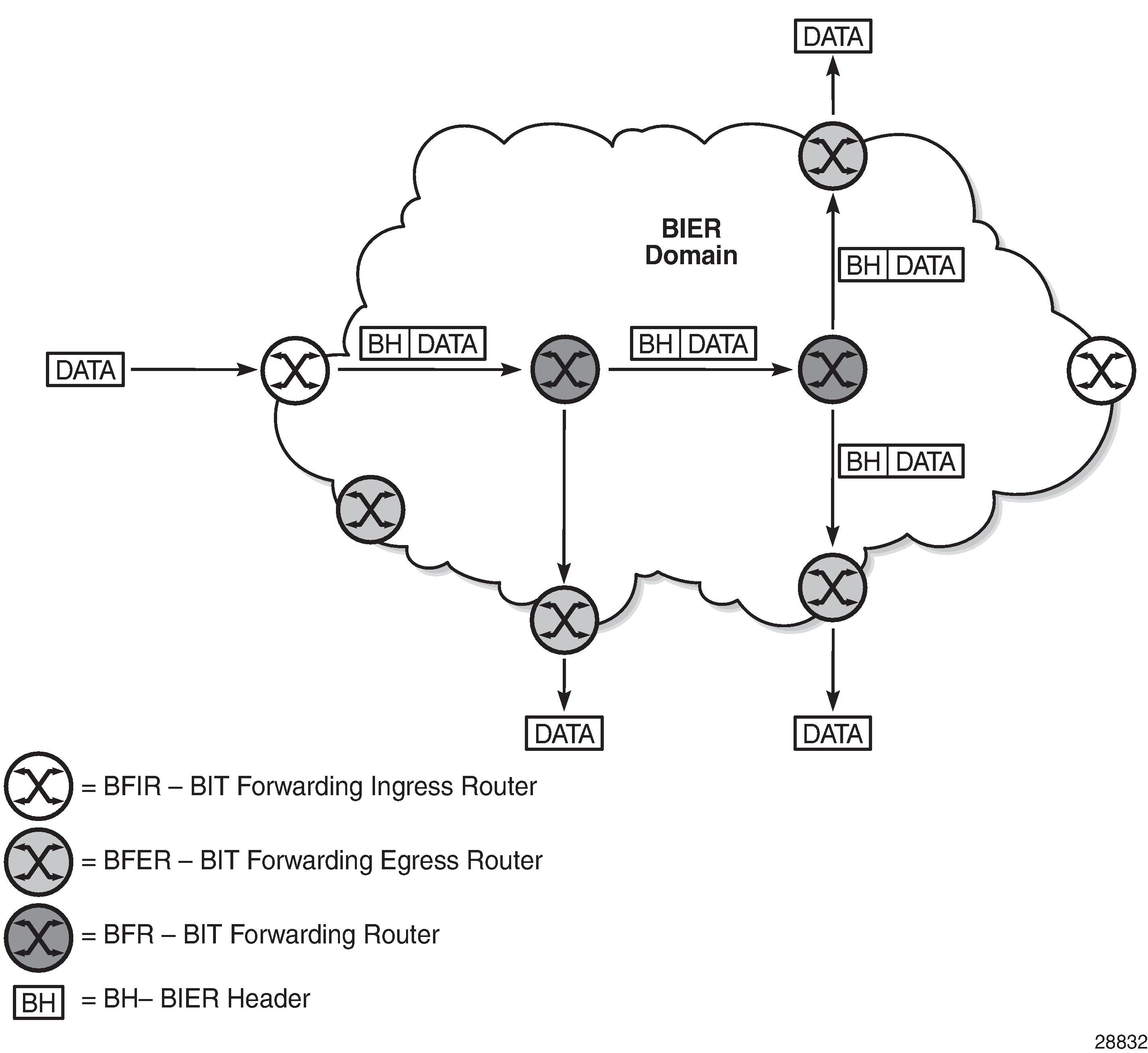
BIER-enabled routers are known as Bit Forwarding Routers (BFRs). A BIER domain contains Bit Forwarding Ingress Routers (BFIRs), Bit Forwarding Egress Routers (BFERs), and transit BFRs; see Bit Forwarding Router types. A router can be a BFIR for one flow, and at the same time be a BFER or a transit BFR for other flows. A BFIR adds a BIER header holding the information used by the BIER forwarding procedures to the multicast packets entering the BIER domain. A BFER removes the BIER header when forwarding the packets out of the BIER domain. The BIER encapsulated data can be further encapsulated in MPLS, where a BIER forwarding table is identified through an MPLS label on the adjacent node. BIER tunnels can build a fully meshed multicast network, thereby providing multicast interconnections between all the PEs in the network.
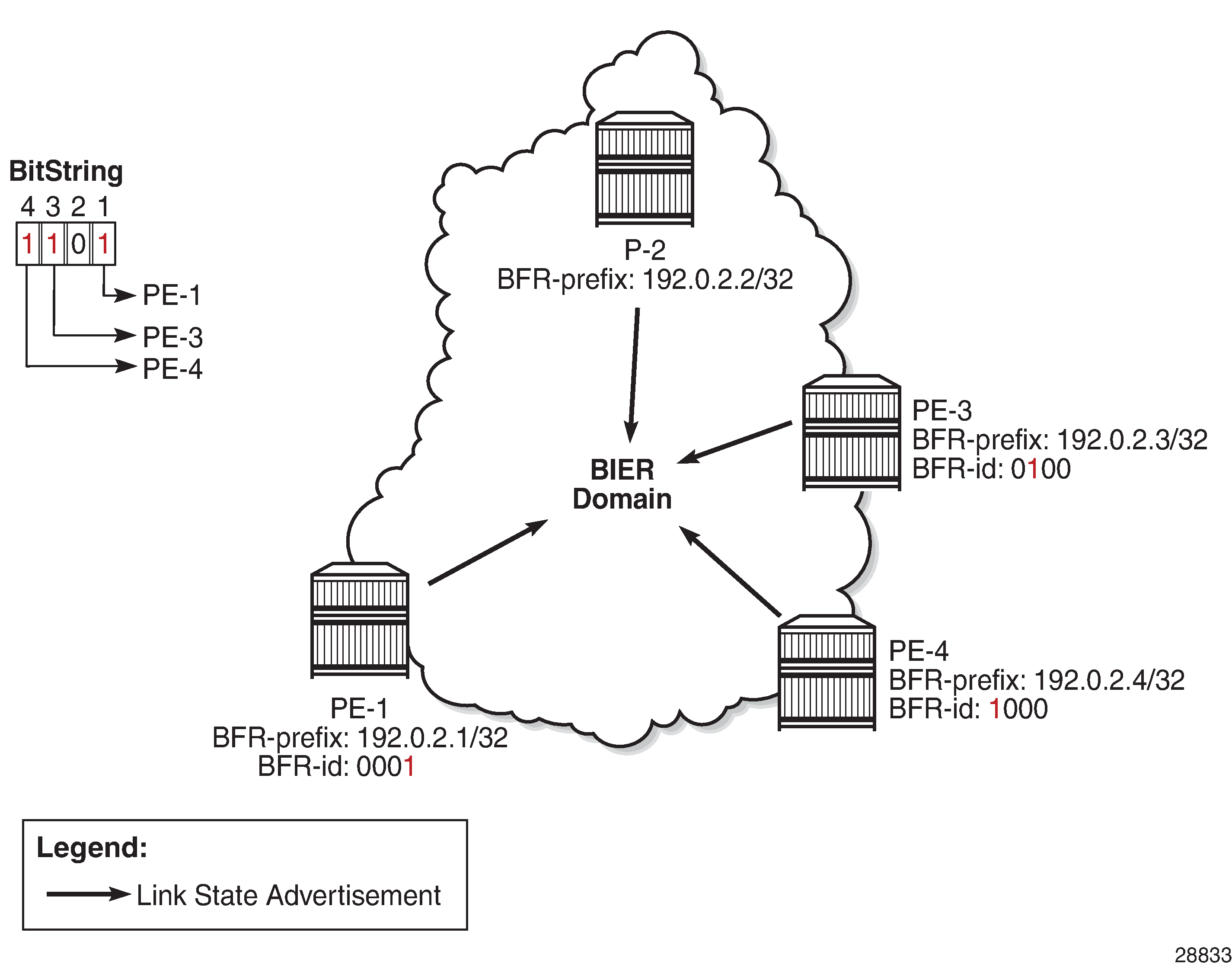
Every BIER receiver has a BFR prefix and a BFR ID. The BFR ID identifies a unique bit position in a bit string assigned to that BFR; by convention, the rightmost bit is bit number 1. The mapping between the BFR ID and the BFR prefix must be known to all BFRs in the domain; therefore, this information is distributed by the underlying Interior Gateway Protocol (IGP) in new TLVs and sub-TLVs defined in IGP extensions. In the example in BIER control plane: example bit position assignment and advertisement, PE-1 has BFR prefix 192.0.2.1/32 and BFR ID 1, PE-3 has BFR prefix 192.0.2.3/32 and BFR ID 3, and so on. Routers in the core of the network are transit BFRs and, therefore, they are not BIER receivers; they require a BFR prefix but not a BFR ID, so their BFR ID is zero.
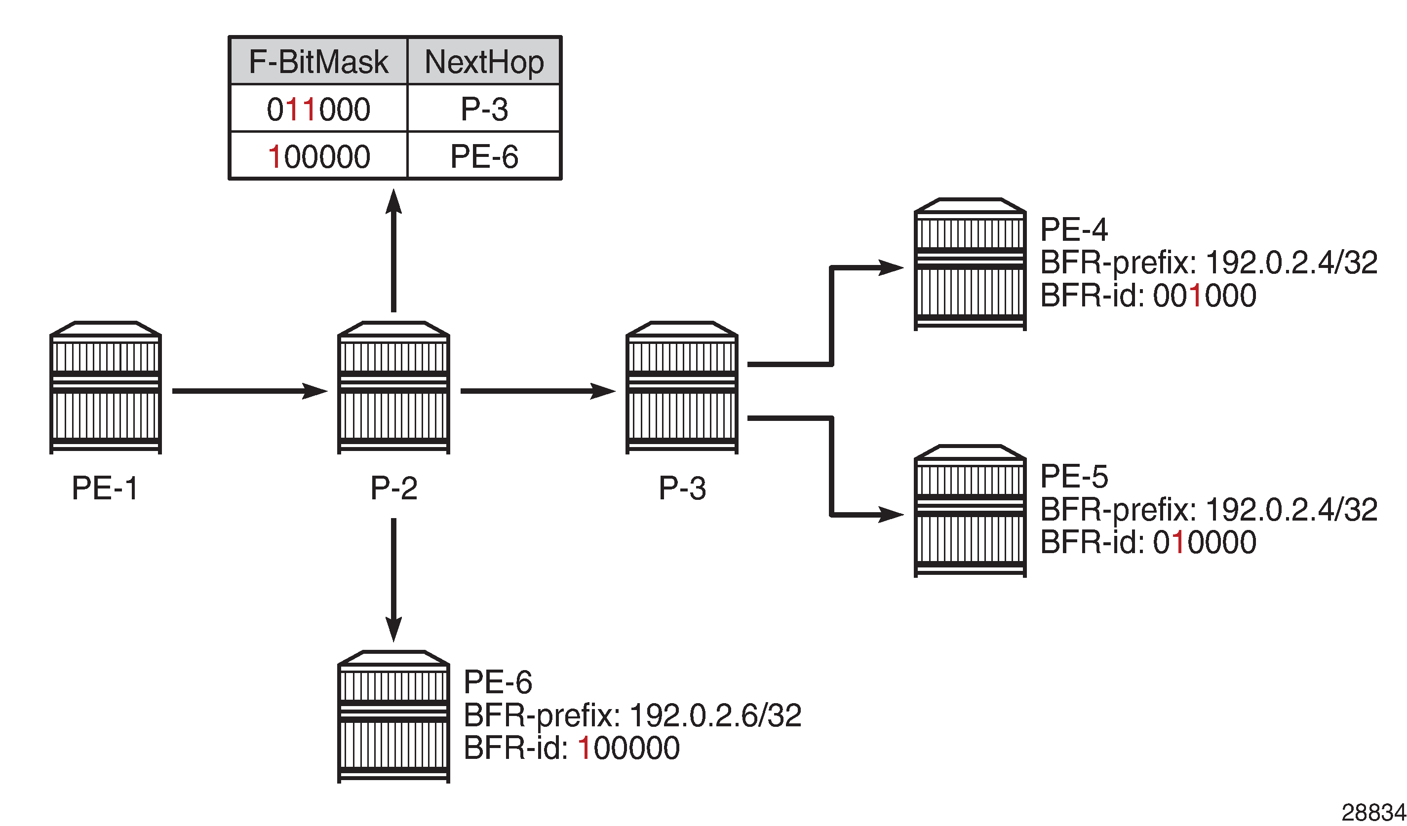
Every BFR in the domain constructs a Bit Indexed Forwarding Table (BIFT) using the shortest unicast path route (SPF). In the construction of a BIFT, every BFR computes the unicast SPF path to each BFR prefix. BFR IDs sharing the same next hop are combined using a logical OR operation, thereby saving memory resources by occupying a single entry in the BIFT; see BIER data plane: example BIER forwarding table for P-2 for an example. On P-2, PE-4 and PE-5 are reachable via P-3, so the forwarding bitmask is 011000 with next hop P-3.
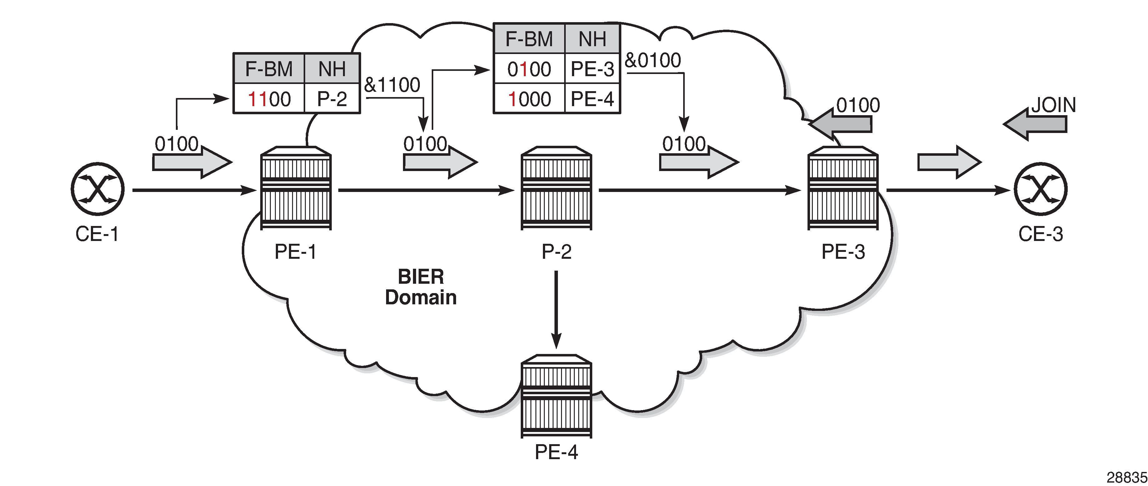
The set of receivers a multicast data packet must be sent to is encoded in a bit string that is embedded in the BIER header. A BFR receiving a multicast data packet uses its BIFT to replicate these packets. When replicating a packet, the bit string in the BIER header is rewritten by the BFRs to avoid loops. Packets are forwarded and replicated hop by hop, following the unicast path from the BFIR to the BFERs.
The example in BIER data plane: example BIER packet forwarding assumes that CE-3 sends an IGMP join to PE-3, which in turn signals the join in MP-BGP to PE-1. PE-1 searches and finds BFR ID 3 in its BIFT with P-2 as the next hop, and logically ANDs (&1100) its bitmap when forwarding the packet to P-2. The AND operation explicitly clears bits for destinations that do not need the packet, thereby preventing potential duplication, and avoiding multicast routing loops. P-2 performs a similar set of steps to forward the packet to PE-3, which delivers the packet to CE-3. The overall result is that only nodes that requested the multicast stream will get that stream, leading to better, more optimal network usage.
A BIER domain contains one or more sub-domains (SDs), where each SD is associated with a single IS-IS or OSPF topology. Each SD is identified by a number in the range 0 to 255, and each BIER domain must contain at least one SD, where SD 0 is the default. If a BIER domain contains more than one SD, each BFR in the domain must be provisioned with the set of SDs it belongs to. The BFR ID of a BFR is a number in the range 1 to 65535, and must be unique within an SD. If a BFR belongs to more than one SD, it may have different BFR IDs in each SD. Nokia recommends using a loopback interface for the BFR prefix. The BFR prefix to BFR ID mapping is flooded within the SD.
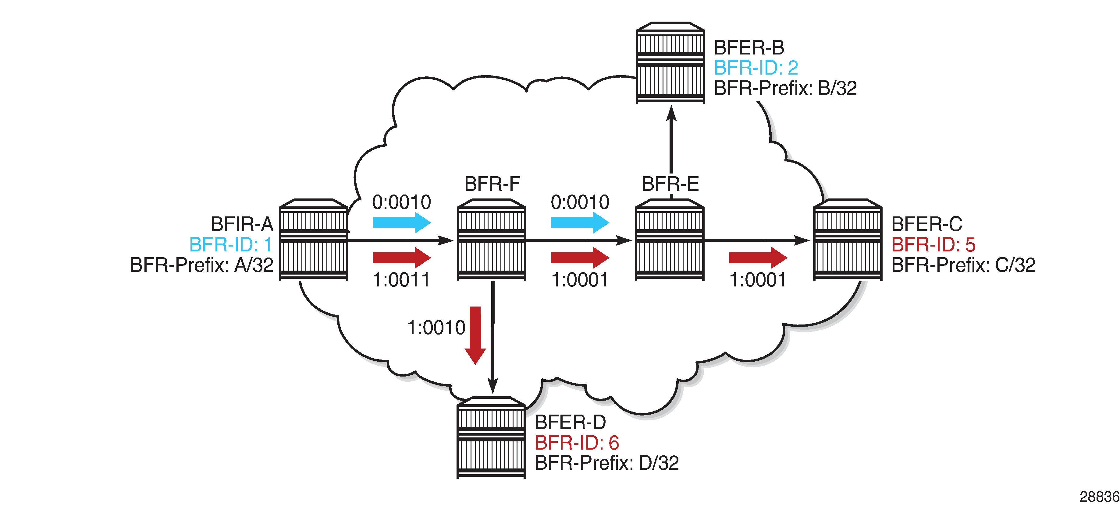
For scalability, a BIER domain contains one or more BIER sets, where each BIER set is identified by a Set Identifier [SI]. The Bit String Length (BSL) dictates how many BFRs can be represented in a BIER set. The BSL, the SI, and the Bit Position (BP) are encoded in the BIER header, where the SI and the BP are derived from the BFR ID. Assuming a BSL of 256, BPs can range from 1 to 256 in BIER set 0. If more than 256 BFIRs and BFERs are required, a second BIER set is required with SI 1, where the BP can again range from 1 to 256. However, if a multicast flow has multiple receivers in different BIER sets on the same outgoing interface, the packet must be replicated to every BIER set.
BIER sets provides an example where BSL is 4 bits, and BFER B, C, and D are interested in the same stream entering the BIER domain at BFIR A. Because BFER C and D have BFR ID 5 and 6, respectively, they are part of SI 1, and BFIR A has to make two copies of the stream; a first (blue) copy to reach BFER-B, and a second (red) copy to reach BFER C and BFER D. Therefore, Nokia recommends assigning BFR IDs as dense as possible; for example, in consecutive order starting from 1.
BIER is encapsulated in MPLS and the MPLS label for each forwarding table (identified through BSL, SI, and SD) is distributed through IS-IS; the BSL is 256 and the maximum number of BIER sets is 16. RFC 8401 defines the extensions needed for distributing BIER information in IS-IS.
Multicast VPN over BIER
Multicast VPN (MVPN) or Next Generation IP Multicast in an IP-VPN (NG-MVPN) architectures describe a set of virtual routing and forwarding (VRF) or virtual private routed networks (VPRNs) that support the transport of multicast traffic across a provider network. MVPNs are defined in RFC 6513 and RFC 6514.
The NG-MVPN Configuration with MPLS and NG-MVPN Configuration with PIM chapters provide examples where the provider tunnels are signaled through either MLDP or PIM.
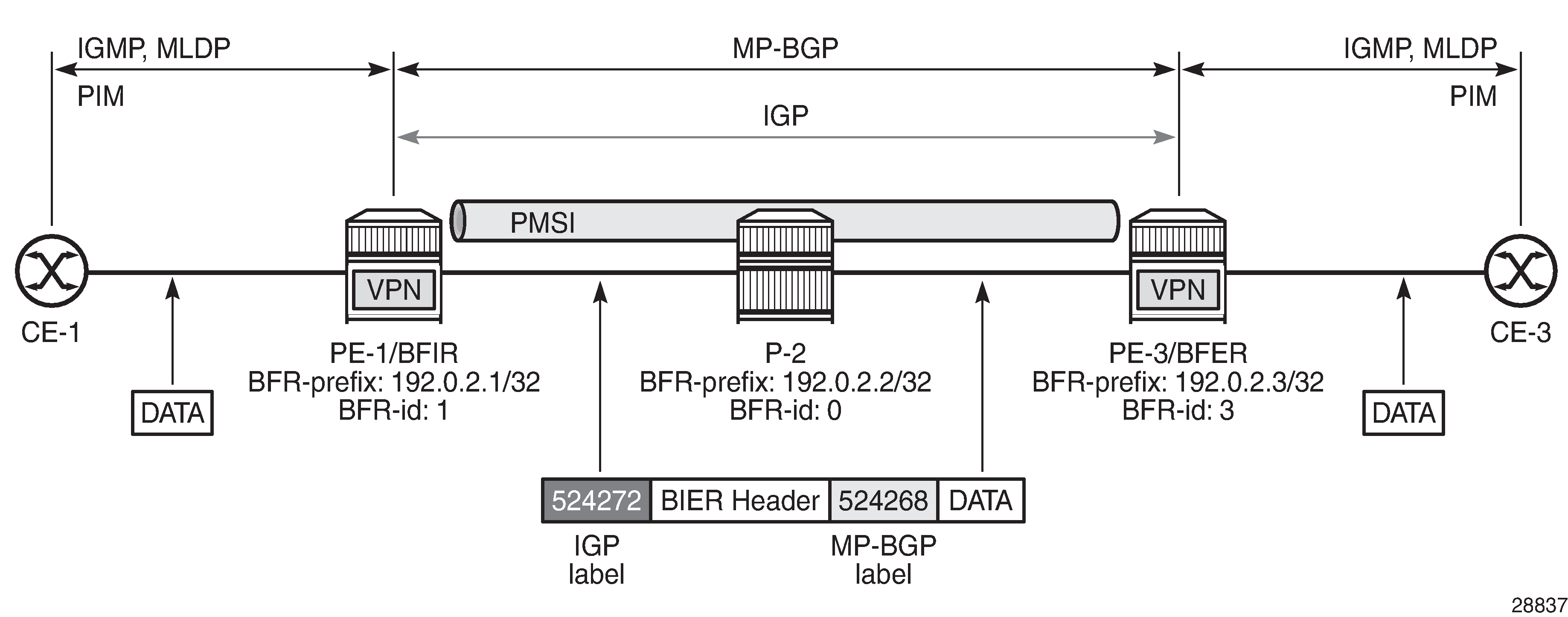
In this chapter, MVPN is used as the overlay to BIER in a single Autonomous System (AS). The MP-BGP control plane is used for the Auto-Discovery (A-D) of the MVPN memberships, the provider tunnel (P-tunnel) signaling, and the customer route (C-route) signaling; see MVPN over BIER.
BIER supports the use of Inclusive PMSIs (I-PMSIs) and Selective PMSIs (S-PMSIs). In the case of I-PMSI, the A-D route signaling, P-tunnel instantiation, and C-multicast routing information are restricted to the I-PMSI, where every BFIR and BFER participating in the MVPN receives every packet forwarded onto the I-PMSI. This way BFIRs and BFERs are interconnected in full mesh. Bandwidth utilization can be optimized by using S-PMSIs, where the C-flow is sent only to BFERs that have interested receivers, and where explicit tracking is used to create the list of interested receivers. The C-flow will be moved from I-PMSI to S-PMSI by the BFIR when a configured data threshold is reached.
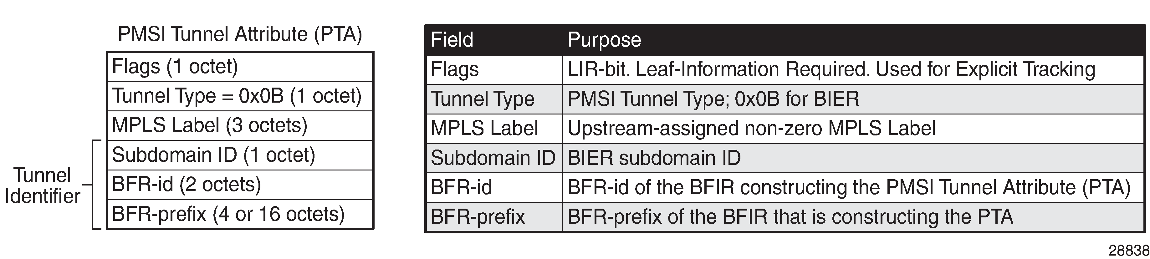
The MP-BGP UPDATE messages used to establish the I-PMSI and the S-PMSI tunnels include the PMSI Tunnel Attribute (PTA), where the tunnel type is set to BIER, and where the MPLS label value is the upstream assigned MPLS label that identifies the VRF; see PTA: PMSI tunnel attribute. By using BIER, multicast provisioning in the core can be simplified; the core routers must be provisioned for BIER, but not for PIM, MLDP, or RSVP-TE. A PIM-free core can be created where no multicast state needs to be maintained.
A multicast client joining a group through IGMP, MLD, or PIM results in the VRF sending an MP-BGP Source-Join message to the BFIR. The BFIR responds with a Source-AD message and establishes an S-PMSI tunnel if S-PMSI is enabled for the VPRN. Next, the S-PMSI tunnel is used to transport the C-flow from the BFIR to the BFER. Otherwise, the I-PMSI tunnel is used for transporting the C-flow.
On CE to PE links, PIM Hello messages are used to establish C-PIM adjacencies. Also between the PEs, across the I-PMSIs, adjacencies are established, not using PIM but using MP-BGP instead. The announcement of MP-REACH-NLRI Intra-AS I-PMSI A-D routes in the discovery process serves as the means to establish the PE-PE adjacencies. A response of the corresponding MP-UNREACH-NLRI results in the adjacency being dropped.
Configuration
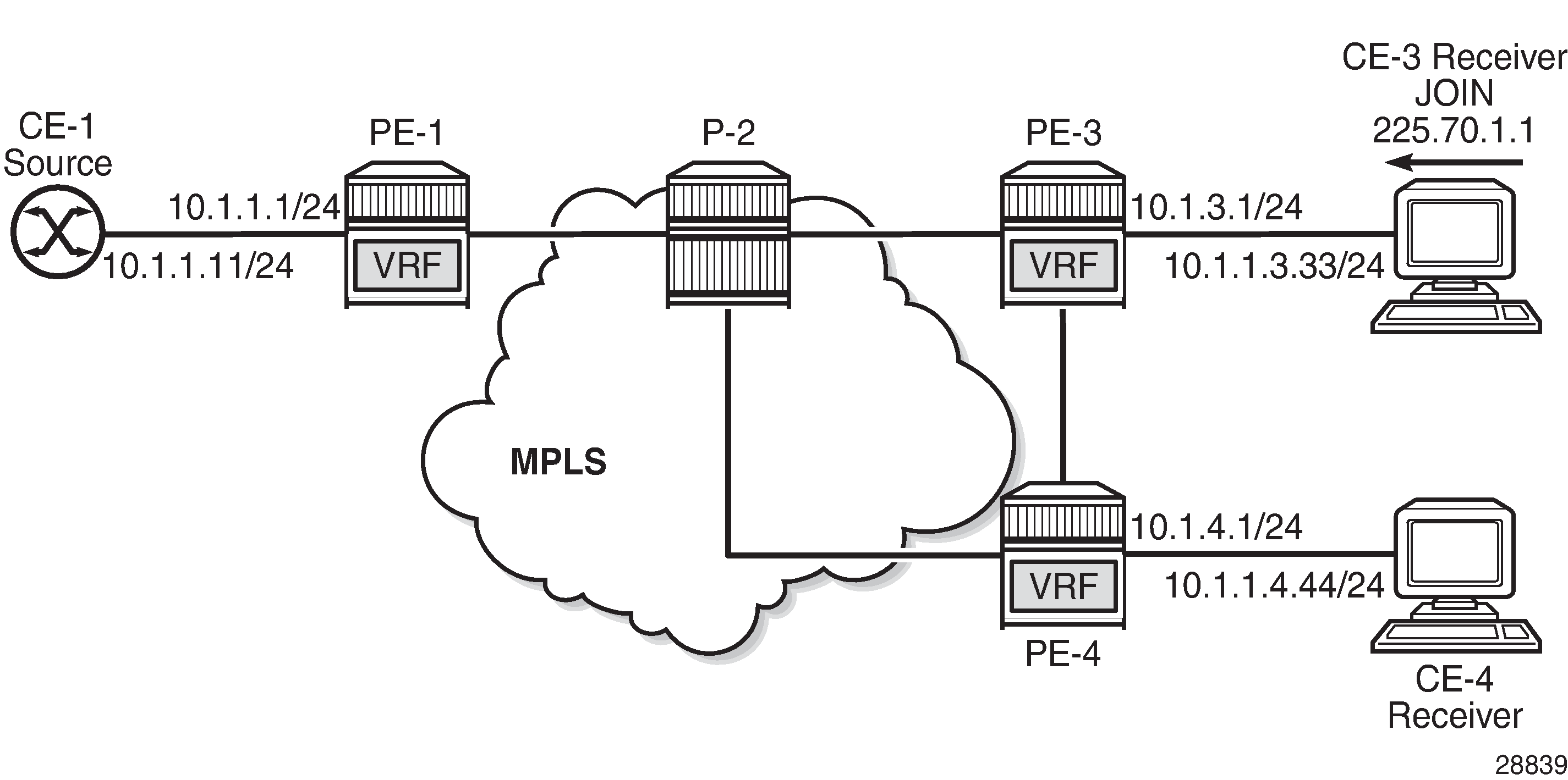
The configuration used in this chapter is shown in Intra-AS NG-MVPN over BIER. IS-IS is the interior gateway protocol (IGP) used in AS 64496, and all nodes are at IS-IS level 2. These nodes share the same BIER domain and sub-domain (0). A multicast stream with group address 225.70.1.1 is transmitted by source 10.1.1.11 connected to PE-1. CE-3 and CE-4 are multicast receivers connected to PE-3 and PE-4, respectively. VPRN 1 is defined in PE-1, PE-3, and PE-4, and uses NG-MVPN for transporting the multicast traffic through the core of the network. See the NG-MVPN Configuration with MPLS and the NG-MVPN Configuration with PIM chapters for more information about NG-MVPN. The BFR IDs used by PE-1, PE-3, and PE-4 are 1, 3, and 4, respectively, so they are part of a single set with SI 0.
The initial configuration on the PE nodes includes the following:
Cards, MDAs, ports
Router interfaces
IS-IS
BGP configuration
BGP is required at the core of the network, using the VPN IPv4 and MVPN IPv4 address families in support of unicast and multicast for VPRN services. PE-1, PE-3, and PE-4 are clients of the route reflector located in P-2. The BGP configuration on PE-1, PE-3, and PE-4 is as follows:
# on PE-1, PE-3, and PE-4:
configure {
    router "Base"  {
        autonomous-system 64496
        bgp {
            vpn-apply-export true
            vpn-apply-import true
            rapid-withdrawal true
            family {
                ipv4 false
                vpn-ipv4 true
                mvpn-ipv4 true
            }
            rapid-update {
                vpn-ipv4 true
                mvpn-ipv4 true
            }
            group "IBGP" {
            }
            neighbor "192.0.2.2" {
                group "IBGP"
                peer-as 64496
            }
        }
The route reflector P-2 is configured as follows:
# on P-2:
configure {
    router "Base"  {
        autonomous-system 64496
        bgp {
            vpn-apply-export true
            vpn-apply-import true
            rapid-withdrawal true
            family {
                ipv4 false
                vpn-ipv4 true
                mvpn-ipv4 true
            }
            cluster {
                cluster-id 0.0.0.1
            }
            rapid-update {
                vpn-ipv4 true
                mvpn-ipv4 true
            }
            group "IBGP" {
                peer-as 64496
            }
            neighbor "192.0.2.1" {
                group "IBGP"
            }
            neighbor "192.0.2.3" {
                group "IBGP"
            }
            neighbor "192.0.2.4" {
                group "IBGP"
            }
        }
BIER configuration
All the nodes in the topology have a BIER template "bier-tmpl0"; however, the content for that template is different on each node. Although multiple sub-domains can be defined through the range command, in this example all nodes in the topology are in the single sub-domain 0 of the BIER domain.
PE-1, PE-3, and PE-4 are the termination points for the BIER tunnels; therefore, they require a BFR ID. For PE-1, PE-3, and PE-4, the system addresses are used as the prefix, and the BFR IDs are set to 1, 3, and 4, respectively. For brevity, only the BIER template on PE-1 is shown:
# on PE-1:
configure {
    router "Base"  {
        bier {
            admin-state enable
            template "bier-tmpl0" {
                admin-state enable
                sub-domain 0 end 0 {
                    bfr-id 1            # on PE-3: 3; on PE-4: 4
                    prefix 192.0.2.1    # on PE-3: 192.0.2.3; on PE-4: 192.0.2.4
                }
            }
        }
P-2 is a transit BFR, so P-2 does not require a BFR ID. Only the BFR prefix is configured in the BIER template for P-2, as follows:
# on P-2:
configure {
    router "Base"  {
        bier {
            admin-state enable
            template "bier-tmpl0" {
                admin-state enable
                sub-domain 0 end 0 {
                    prefix 192.0.2.2
                }
            }
        }
The BIER template must be applied to the IGP, so that the MPLS labels required for the BIER tunnels are distributed through the IGP, which is IS-IS.
In the example topology shown in Intra-AS NG-MVPN over BIER, the IS-IS configuration is similar on all nodes, with level-capability set to level-2, and BIER template "bier-templ0" applied and enabled (admin-state enable) at level 2, as follows. For brevity, only the IS-IS configuration for PE-1 is shown.
# on PE-1:
configure {
    router "Base" {
        isis 0 {
            admin-state enable
            level-capability 2
            traffic-engineering true
            area-address [49.0001]
            interface "int-PE-1-P-2" {
                interface-type point-to-point
            }
            interface "system" {
            }
            level 2 {
                wide-metrics-only true
                bier {
                    admin-state enable
                    template "bier-tmpl0"
                }
            }
        }
The status of IS-IS shows that BIER is active at L2 using template bier-tmpl0. BIER must be active on all nodes in the topology, but for brevity only the IS-IS status on PE-1 is shown, as follows:
[/]
A:admin@PE-1# show router isis status

===============================================================================
Rtr Base ISIS Instance 0 Status
===============================================================================
ISIS Cfg System Id           : 0000.0000.0000
ISIS Oper System Id          : 1920.0000.2001
ISIS Cfg Router Id           : 0.0.0.0
ISIS Oper Router Id          : 192.0.2.1
ISIS Cfg IPv6 Router Id      : ::
ISIS Oper IPv6 Router Id     : ::
ASN                          : 0
Admin State                  : Up
Oper State                   : Up
Ipv4 Routing                 : Enabled
---snip---

L2 Bier Template             : bier-tmpl0, Enabled
---snip---
BIER allocates an MPLS label per BIER set, and 16 consecutive labels are allocated to accommodate the 16 BIER sets supported by SR OS. This label range is shown together with the BFR ID and BFR prefix from the BIER template in the BIER database. For PE-1, the BIER database is as follows:
[/]
A:admin@PE-1# show router bier database

===============================================================================
BIER Database
===============================================================================
Template                         MT             Sub-domain     BSL
BFR-ID                           Start          End            Total
BFR-Prefix
-------------------------------------------------------------------------------
bier-tmpl0                       ipv4-unicast   0              256
1                                524272         524287         16
192.0.2.1

===============================================================================
BIER Database entries : 1
===============================================================================
On P-2, the BIER database looks similar, but the BFR ID is zero indicating that no BFR ID is defined, as follows:
[/]
A:admin@P-2# show router bier database

===============================================================================
BIER Database
===============================================================================
Template                         MT             Sub-domain     BSL
BFR-ID                           Start          End            Total
BFR-Prefix
-------------------------------------------------------------------------------
bier-tmpl0                       ipv4-unicast   0              256
0                                524272         524287         16
192.0.2.2

===============================================================================
BIER Database entries : 1
===============================================================================
IS-IS distributes the BIER information across all the BFRs in the network using link state packets (shown as "LSP" in the output); consequently, this information is the same on all BFRs. As an example, the details for LSP PE-3.00-00 show that for PE-3 at level 2, the BFR ID is 3, and the MPLS label value is 524272:
[/]
A:admin@PE-1# show router isis database PE-3.00-00 detail

===============================================================================
Rtr Base ISIS Instance 0 Database (detail)
===============================================================================

Displaying Level 1 database
-------------------------------------------------------------------------------
Level (1) LSP Count : 0

Displaying Level 2 database
-------------------------------------------------------------------------------
LSP ID    : PE-3.00-00                                  Level     : L2
Sequence  : 0x5                    Checksum  : 0x92f8   Lifetime  : 1028
Version   : 1                      Pkt Type  : 20       Pkt Ver   : 1
Attributes: L1L2                   Max Area  : 3        Alloc Len : 155
SYS ID    : 1920.0000.2003         SysID Len : 6        Used Len  : 155

TLVs :
  Area Addresses:
    Area Address : (3) 49.0001
  Supp Protocols:
    Protocols     : IPv4
  IS-Hostname   : PE-3
  Router ID   :
    Router ID   : 192.0.2.3
  I/F Addresses :
    I/F Address   : 192.168.34.1
    I/F Address   : 192.168.23.2
    I/F Address   : 192.0.2.3
  TE IS Nbrs   :
    Nbr   : P-2.00
    Default Metric  : 10
    Sub TLV Len     : 12
    IF Addr   : 192.168.23.2
    Nbr IP    : 192.168.23.1
  TE IS Nbrs   :
    Nbr   : PE-4.00
    Default Metric  : 10
    Sub TLV Len     : 12
    IF Addr   : 192.168.34.1
    Nbr IP    : 192.168.34.2
  TE IP Reach   :
    Default Metric  : 10
    Control Info:    , prefLen 30
    Prefix   : 192.168.23.0
    Default Metric  : 10
    Control Info:    , prefLen 30
    Prefix   : 192.168.34.0
    Default Metric  : 0
    Control Info:   S, prefLen 32
    Prefix   : 192.0.2.3
    Sub TLV   :
      Bier::Bier Algo:0, IGP Algo:0, SD id:0, BFR id:3
          MPLS Encap  Max SI:16, BS Len:3(256), Label:524272

Level (2) LSP Count : 1
-------------------------------------------------------------------------------
Control Info     : D = Prefix Leaked Down
                   S = Sub-TLVs Present
---snip---
A shorter and more convenient way for obtaining the BIER information directly is through the bier-info command. On PE-3, the BIER information is as follows:
[/]
A:admin@PE-3# show router isis bier-info

===============================================================================
Rtr Base ISIS Instance 0 Bier Info
===============================================================================

Displaying Level 1 BIER info
-------------------------------------------------------------------------------

Displaying Level 2 BIER info
-------------------------------------------------------------------------------
LSP ID    : PE-1.00-00
    MT ID    : 0
    Prefix   : 192.0.2.1
    Sub TLV   :
      Bier::Bier Algo:0, IGP Algo:0, SD id:0, BFR id:1
          MPLS Encap  Max SI:16, BS Len:3(256), Label:524272

LSP ID    : P-2.00-00
    MT ID    : 0
    Prefix   : 192.0.2.2
    Sub TLV   :
      Bier::Bier Algo:0, IGP Algo:0, SD id:0, BFR id:0
          MPLS Encap  Max SI:16, BS Len:3(256), Label:524272

LSP ID    : PE-3.00-00
    MT ID    : 0
    Prefix   : 192.0.2.3
    Sub TLV   :
      Bier::Bier Algo:0, IGP Algo:0, SD id:0, BFR id:3
          MPLS Encap  Max SI:16, BS Len:3(256), Label:524272

LSP ID    : PE-4.00-00
    MT ID    : 0
    Prefix   : 192.0.2.4
    Sub TLV   :
      Bier::Bier Algo:0, IGP Algo:0, SD id:0, BFR id:4
          MPLS Encap  Max SI:16, BS Len:3(256), Label:524272

===============================================================================
No BIER tunnels are available, because no MVPN-enabled services are created yet. As stated before, SR OS allocates one label per BIER set, and on PE-1 they are as follows:
[/]
A:admin@PE-1# show router mpls-labels label 32 524287 bier

=================================================================
MPLS Labels from 32 to 524287 (Owner: BIER)
=================================================================
Label               Label Type          Label Owner
-----------------------------------------------------------------
524272              dynamic             BIER
524273              dynamic             BIER
524274              dynamic             BIER
524275              dynamic             BIER
524276              dynamic             BIER
524277              dynamic             BIER
524278              dynamic             BIER
524279              dynamic             BIER
524280              dynamic             BIER
524281              dynamic             BIER
524282              dynamic             BIER
524283              dynamic             BIER
524284              dynamic             BIER
524285              dynamic             BIER
524286              dynamic             BIER
524287              dynamic             BIER
-----------------------------------------------------------------
In-use labels (Owner: BIER) in specified range  : 16
In-use labels (Owner: All) in specified range   : 16
In-use labels in entire range                   : 16
=================================================================
Based on the link state packets distributed across the network, every BFR generates a BIER routing table and a BIER forwarding table. The BIER routing table defines the interface, next hop, and neighbor to use for all BFRs. On PE-1, the BIER routing table is as follows:
[/]
A:admin@PE-1# show router bier routing

===============================================================================
Destination Prefix                          Bfr-ID          Age
  Neighbor
    Nexthop
    Interface
  Backup Neighbor
    Backup Nexthop
    Backup Interface
-------------------------------------------------------------------------------

===============================================================================
BIER Routing Database Sub-Domain 0 BSL 256
===============================================================================
192.0.2.2                                   0               0d 00:04:02
  192.0.2.2
    192.168.12.2
    int-PE-1-P-2

192.0.2.3                                   3               0d 00:03:55
  192.0.2.2
    192.168.12.2
    int-PE-1-P-2

192.0.2.4                                   4               0d 00:03:46
  192.0.2.2
    192.168.12.2
    int-PE-1-P-2

===============================================================================
Total (Sub-Domain 0): 3
===============================================================================
Total BIER Routing entries : 3
===============================================================================
The BIER forwarding table has one entry per BIER neighbor, defining the next hop, interface, and forwarding bit mask. On PE-1, the BIER forwarding table is as follows. For neighbor 192.0.2.2, the forwarding bit mask is 0xC in hexadecimal, or 0b1100 in binary. Using the convention that the rightmost bit is bit 1, this means bits 3 and 4 are set, and these bits correspond to BFRs with system addresses 192.0.2.3 and 192.0.2.4, according their BFR ID.
[/]
A:admin@PE-1# show router bier forwarding

===============================================================================
Neighbor
  Nexthop
  Interface
    Backup Neighbor
      Backup Nexthop
      Backup Interface
  [SI]: Label
    Forwarding Bit Mask
      BFR-ID : Prefix
      [SI]: Label (Backup)
        Forwarding Bit Mask
          BFR-ID : Prefix
-------------------------------------------------------------------------------

===============================================================================
BIER Forwarding Database Sub-Domain 0 BSL 256
===============================================================================
192.0.2.2
  192.168.12.2
  int-PE-1-P-2
  [0]: 524272
    0x000000000000000000000000000000000000000000000000000000000000000c
      3 : 192.0.2.3
      4 : 192.0.2.4
===============================================================================
Total (Sub-Domain 0): 1
===============================================================================
Total BIER Forwarding entries : 1
===============================================================================
No multicast configuration is required in the base routers of the BFERs, BFIRs, and the transit BFR, resulting in a simplified configuration. Only the BFIRs and BFERs must be configured with MVPN-enabled VPRN services.
Service configuration
The full configuration of VPRN "VRF-1" on PE-1 is as follows. The int-PE-1-CE-1 interface provides the connection to the multicast source. PIM is enabled for all interfaces in the service through the apply-to all command. To support BIER, MVPN is enabled with auto-discovery set to type bgp and c-mcast-signaling set to bgp. BIER is enabled (admin-state enable) for inclusive and selective provider tunnels for sub-domain 0.
# on PE-1:
configure {
    service {
        vprn "VRF-1" {
            admin-state enable
            description "VPRN between PE-1, PE-3 and PE-4"
            service-id 1
            customer "1"
            pim {
                apply-to all
            }
            mvpn {
                c-mcast-signaling bgp
                auto-discovery {
                    type bgp
                }
                vrf-target {
                    unicast true
                }
                provider-tunnel {
                    inclusive {
                        bier {
                            admin-state enable
                            sub-domain 0
                        }
                    }
                    selective {
                        data-threshold {
                            group-prefix 224.0.0.0/4 {
                                threshold 10
                            }
                        }
                        bier {
                            admin-state enable
                            sub-domain 0
                        }
                    }
                }
            }
            bgp-ipvpn {
                mpls {
                    admin-state enable
                    route-distinguisher "192.0.2.1:1"
                    vrf-target {
                        community "target:64496:1"
                    }
                    auto-bind-tunnel {
                        resolution any
                    }
                }
            }
            interface "int-PE-1-CE-1" {        # interface to multicast source
                ipv4 {
                    primary {
                        address 10.1.1.1
                        prefix-length 24
                    }
                }
                sap 1/1/c10/1 {
                }
            }
        }
The MVPN configuration for VRF-1 on PE-3 and PE-4 is the same. However, PE-3 and PE-4 provide connections to multicast clients CE-3 and CE-4, and they have IGMP configured. Because the configurations for PE-3 and PE-4 are similar, only the configuration of PE-3 is provided.
# on PE-3:
configure {
    service {
        vprn "VRF-1" {
            admin-state enable
            description "VPRN between PE-1, PE-3 and PE-4"
            service-id 1
            customer "1"
            igmp {
                ssm-translate {
                    group-range start 225.70.1.1 end 225.70.255.255 {
                        source 10.1.1.11 { }
                    }
                }
                interface "int-PE-3-CE-3" {        # on PE-4: int-PE-4-CE-4
                }
            }
            pim {
                apply-to all
            }
            mvpn {
                c-mcast-signaling bgp
                auto-discovery {
                    type bgp
                }
                vrf-target {
                    unicast true
                }
                provider-tunnel {
                    inclusive {
                        bier {
                            admin-state enable
                            sub-domain 0
                        }
                    }
                    selective {
                        data-threshold {
                            group-prefix 224.0.0.0/4 {
                                threshold 10
                            }
                        }
                        bier {
                            admin-state enable
                            sub-domain 0
                        }
                    }
                }
            }
            bgp-ipvpn {
                mpls {
                    admin-state enable
                    route-distinguisher "192.0.2.3:1"    # on PE-4: 192.0.2.4:1
                    vrf-target {
                        community "target:64496:1"
                    }
                    auto-bind-tunnel {
                        resolution any
                    }
                }
            }
            interface "int-PE-3-CE-3" {        # on PE-4: int-PE-4-CE-4
                ipv4 {
                    primary {
                        address 10.1.3.1       # on PE-4: 10.1.4.1/24
                        prefix-length 24
                    }
                }
                sap 1/1/c10/1 {
                }
            }
        }
With VRF-1 on PE-1, PE-3, and PE-4 configured as previously described, VPN and MVPN routes are exchanged, as follows:
[/]
A:admin@PE-1# show router bgp summary all

===============================================================================
BGP Summary
===============================================================================
Legend : D - Dynamic Neighbor
===============================================================================
Neighbor
Description
ServiceId          AS PktRcvd InQ  Up/Down   State|Rcv/Act/Sent (Addr Family)
                      PktSent OutQ
-------------------------------------------------------------------------------
192.0.2.2
Def. Inst       64496      26    0 00h07m08s 3/2/1 (VpnIPv4)
                           22    0           3/2/1 (MvpnIPv4)

-------------------------------------------------------------------------------
The MVPN status for VRF-1 can be verified, as follows. For brevity, only the status on PE-1 is shown; BIER is used for I-PMSI and S-PMSI in SD 0, and the I-PMSI tunnel name is mpls-if-73728.
[/]
A:admin@PE-1# show router service-name "VRF-1" mvpn

===============================================================================
MVPN 1 configuration data
===============================================================================
signaling          : Bgp                  auto-discovery     : Default
UMH Selection      : Highest-Ip           SA withdrawn       : Disabled
intersite-shared   : Enabled              Persist SA         : Disabled
vrf-import         : N/A
vrf-export         : N/A
vrf-target         : unicast
C-Mcast Import RT  : target:192.0.2.1:2

ipmsi              : bier
sub-domain         : 0
i-pmsi P2MP AdmSt  : Up
i-pmsi Tunnel Name : mpls-if-73728
service-reserved-l*: 0

BSR signalling     : none
Wildcard s-pmsi    : Disabled             Suppress i-pmsi    : Disabled
Multistream-SPMSI  : Disabled
spmsi              : bier
sub-domain         : 0
s-pmsi P2MP AdmSt  : Up
max-p2mp-spmsi     : 10
data-delay-interval: 3 seconds
enable-asm-mdt     : N/A
data-threshold     : 224.0.0.0/4 --> 10 kbps

ipmsi UMH RM       : Disabled

spmsi UMH RM       : Disabled
===============================================================================
* indicates that the corresponding row element may have been truncated.
The receiver CE-3 located at address 10.1.3.33/24 and connected to PE-3 then joins group 225.70.1.1, so VRF-1 creates an IGMP state, and (*,255.70.1.1) is forwarded to interface int-PE-3-CE-3, as follows:
[/]
A:admin@PE-3# show router service-name "VRF-1" igmp group interfaces
===============================================================================
IGMP Interface Groups
===============================================================================

(*,225.70.1.1)                                            UpTime: 0d 00:00:09
    Fwd List  : int-PE-3-CE-3
-------------------------------------------------------------------------------
Entries : 1
===============================================================================
VRF-1 on PE-3 also creates a PIM state for group 225.70.1.1, where the incoming S-PMSI interface is mpls-if-73731, and the outgoing interface is int-PE-3-CE-3, as follows:
[/]
A:admin@PE-3# show router service-name "VRF-1" pim group 225.70.1.1 detail

===============================================================================
PIM Source Group ipv4
===============================================================================
Group Address      : 225.70.1.1
Source Address     : 10.1.1.11
RP Address         : 0
Advt Router        : 192.0.2.1
Flags              :                    Type               : (S,G)
Mode               : sparse
MRIB Next Hop      : 192.0.2.1
MRIB Src Flags     : remote
Keepalive Timer Exp: 0d 00:02:47
Up Time            : 0d 00:00:46        Resolved By        : rtable-u

Up JP State        : Joined             Up JP Expiry       : 0d 00:00:13
Up JP Rpt          : Not Joined StarG   Up JP Rpt Override : 0d 00:00:00

Register State     : No Info
Reg From Anycast RP: No

Rpf Neighbor       : 192.0.2.1
Incoming Intf      : mpls-if-73729
Incoming SPMSI Intf: mpls-if-73731
Outgoing Intf List : int-PE-3-CE-3

Curr Fwding Rate   : 486.464 kbps
Forwarded Packets  : 2002               Discarded Packets  : 0
Forwarded Octets   : 2766764            RPF Mismatches     : 0
Spt threshold      : 0 kbps             ECMP opt threshold : 7
Admin bandwidth    : 1 kbps
-------------------------------------------------------------------------------
Groups : 1
===============================================================================
On PE-3, the following two incoming BIER tunnels with tunnel IDs 73729 and 73731 have PE-1 as originator:
[/]
A:admin@PE-3# show router bier tunnel prefix 192.0.2.1

===============================================================================
BIER Tunnels
===============================================================================
Tunnel-id           Type                Oper                No. Of Leaves
BFR Prefx           Bfr-ID              Mpls Label          Sub-domain
-------------------------------------------------------------------------------
73729               rx                  In service          0
192.0.2.1           1                   524269              0

73731               rx                  In service          0
192.0.2.1           1                   524271              0

===============================================================================
BIER Tunnel entries : 2
===============================================================================
On PE-3, tunnel interface mpls-if-73729 is an Rx-I-PMSI tunnel:
[/]
A:admin@PE-3# show router service-name "VRF-1" pim tunnel-interface mpls-if-73729

===============================================================================
PIM Interface ipv4 mpls-if-73729
===============================================================================
Interface                        Originator Address   Adm  Opr  Transport Type
-------------------------------------------------------------------------------
mpls-if-73729                    192.0.2.1            Up   Up   Rx-IPMSI
-------------------------------------------------------------------------------
Interfaces : 1
===============================================================================
Tunnel interface mpls-if-73731 is an Rx-S-PMSI tunnel:
[/]
A:admin@PE-3# show router service-name "VRF-1" pim tunnel-interface mpls-if-73731

===============================================================================
PIM Interface ipv4 mpls-if-73731
===============================================================================
Interface                        Originator Address   Adm  Opr  Transport Type
-------------------------------------------------------------------------------
mpls-if-73731                    192.0.2.1            Up   Up   Rx-SPMSI
-------------------------------------------------------------------------------
Interfaces : 1
===============================================================================
The properties of the S-PMSI tunnel on PE-3 match the properties of the BIER tunnel, as follows:
[/]
A:admin@PE-3# show router service-name "VRF-1" pim s-pmsi bier-root-addr 192.0.2.1

===============================================================================
PIM BIER Spmsi tunnels
===============================================================================
Root Addr                              Sub-Domain ID BFR ID        MPLS Lbl
Multistream-ID                         If-Index      Num Vpn SG's  State
-------------------------------------------------------------------------------
192.0.2.1                              0             1             524271
0                                      73731         1             Up

===============================================================================
PIM BIER Spmsi interfaces : 1
===============================================================================
PE-3 signals the join request for group 225.70.1.1 as an MP-BGP Source-Join update message to PE-1, so in turn PE-1 also creates a PIM state. On PE-1, the multicast traffic enters and leaves VRF-1 via interfaces int-PE-1-CE-1 and mpls-if-73731 (S-PMSI), respectively, as follows:
[/]
A:admin@PE-1# show router service-name "VRF-1" pim group 225.70.1.1 detail

===============================================================================
PIM Source Group ipv4
===============================================================================
Group Address      : 225.70.1.1
Source Address     : 10.1.1.11
RP Address         : 0
Advt Router        : 192.0.2.1
Flags              :                    Type               : (S,G)
Mode               : sparse
MRIB Next Hop      : 10.1.1.11
MRIB Src Flags     : direct
Keepalive Timer    : Not Running
Up Time            : 0d 00:02:15        Resolved By        : rtable-u

Up JP State        : Joined             Up JP Expiry       : 0d 00:00:00
Up JP Rpt          : Not Joined StarG   Up JP Rpt Override : 0d 00:00:00

Register State     : No Info
Reg From Anycast RP: No

Rpf Neighbor       : 10.1.1.11
Incoming Intf      : int-PE-1-CE-1
Outgoing Intf List : mpls-if-73728 (mpls-if-73731)

Curr Fwding Rate   : 486.464 kbps
Forwarded Packets  : 5957               Discarded Packets  : 0
Forwarded Octets   : 8232574            RPF Mismatches     : 0
Spt threshold      : 0 kbps             ECMP opt threshold : 7
Admin bandwidth    : 1 kbps
-------------------------------------------------------------------------------
Groups : 1
===============================================================================
The outgoing tunnel interface mpls-if-73728 is an I-PSMI tunnel:
[/]
A:admin@PE-1# show router service-name "VRF-1" pim tunnel-interface "mpls-if-73728"

===============================================================================
PIM Interface ipv4 mpls-if-73728
===============================================================================
Interface                        Originator Address   Adm  Opr  Transport Type
-------------------------------------------------------------------------------
mpls-if-73728                    192.0.2.1            Up   Up   Tx-IPMSI
-------------------------------------------------------------------------------
Interfaces : 1
===============================================================================
The properties of the I-PMSI mpls-if-73728 tunnel interface on PE-1 include the details for the joined multicast group, as follows:
[/]
A:admin@PE-1# show router service-name "VRF-1" pim tunnel-interface "mpls-if-73728" detail

===============================================================================
PIM Interface ipv4 mpls-if-73728
===============================================================================
Admin Status       : Up                 Oper Status        : Up
IPv4 Admin Status  : Up                 IPv4 Oper Status   : Up
DR                 : 192.0.2.1
Auto-created       : No
Transport Type     : MVPN-Pmsi

-------------------------------------------------------------------------------
PIM Group Source
-------------------------------------------------------------------------------
Group Address      : 225.70.1.1
Source Address     : 10.1.1.11
Interface          : mpls-if-73728      Type               : (S,G)
RP Address         : 0.0.0.0
Up Time            : 0d 00:02:57

Join Prune State   : Join               Expires            : Never
Prune Pend Expires : N/A

Assert State       : No Info
-------------------------------------------------------------------------------
Interfaces : 1
===============================================================================
Because VRF-1 is configured to use selective provider tunnels, SR OS creates additional BIER tunnels when joining groups exceed the data threshold of 10 kb/s. With only group 225.70.1.1 joined, the BIER tunnels on PE-1 are as follows:
[/]
A:admin@PE-1# show router bier tunnel

===============================================================================
BIER Tunnels
===============================================================================
Tunnel-id           Type                Oper                No. Of Leaves
BFR Prefx           Bfr-ID              Mpls Label          Sub-domain
-------------------------------------------------------------------------------
73728               tx                  In service          2
192.0.2.1           1                   524269              0

73729               rx                  In service          0
192.0.2.3           3                   524269              0

73730               rx                  In service          0
192.0.2.4           4                   524269              0

73731               tx                  In service          1
192.0.2.1           1                   524271              0

===============================================================================
BIER Tunnel entries : 4
===============================================================================
The properties of the S-PMSI tunnel for group 225.70.1.1 on PE-1 show that the MPLS label 524271 and interface index 73731 are used, as follows. The label and interface index are the same as the highlighted BIER tunnel properties from the preceding command.
[/]
A:admin@PE-1# show router service-name "VRF-1" pim s-pmsi group-ip 225.70.1.1 detail

===============================================================================
PIM BIER Spmsi tunnels
===============================================================================
Root Address       : 192.0.2.1          BFR ID             : 1
Sub Domain         : 0                  Mpls Lbl           : 524271
Multistream ID     : N/A                If Index           : 73731
Num VPN SGs        : 1                  Oper State         : Up

VPN Group Address  : 225.70.1.1
VPN Source Address : 10.1.1.11
State              : TX Joined          Mdt Threshold      : 10
Join Timer         : 0                  Hold Down Timer    : 36
SG Age             : 204                Expiry Timer       : 0
Threshold enabled  : False              Receiver count     : 0
-------------------------------------------------------------------------------
===============================================================================
PIM BIER Spmsi interfaces : 1
===============================================================================
In summary, for the multicast traffic originated by source CE-1 to VRF-1 on PE-1 passes the core network through a BIER tunnel and leaves VRF-1 on PE-3 to terminate in receiver CE-3. A transit node in the core network (P-2 in the example topology in Intra-AS NG-MVPN over BIER) does not maintain any multicast state for the multicast stream.
With MVPN-enabled VPRN 1 instances defined on PE-1, PE-3, and PE-4, and group 225.70.1.1 active, an entry is added to the MVPN list. On PE-1, this list is as follows:
[/]
A:admin@PE-1# show router mvpn-list type bier

Legend: Sig = Signal  Pim-a = pim-asm  Pim-s = pim-ssm  A-D = Auto-Discovery
SR = Sender-Receiver  SO = Sender-Only  RO = Receiver-Only
SRv6 = P2MP-SRv6  SR-MPLS / SR-M = P2MP-SR-MPLS

===============================================================================
MVPN List
===============================================================================
VprnID    A-D      iPmsi/sPmsi GroupAddr/Lsp-Template          IPv4(S,G)/(*,G)
           Sig      Mdt-Type                                    IPv6(S,G)/(*,G)
-------------------------------------------------------------------------------
1         Default  Bier/Bier   N/A                             1/0
           Bgp      SR                                          0/0
-------------------------------------------------------------------------------
Total Mvpns : 1
===============================================================================

==============================================================================
Total                   PIM      RSVP     MLDP     BIER     SR-MPLS  SRv6
------------------------------------------------------------------------------
I-PMSI tunnels          0        0        0        3        0        0
TX S-PMSI tunnels       0        0        0        1        0        0
RX S-PMSI tunnels       0        0        0        0        0        0
RX PSEUDO S-PMSI tunne* 0        0        0        0        0        0
------------------------------------------------------------------------------
Total IPv4 (S,G)/(*,G) : 1/0
Total IPv6 (S,G)/(*,G) : 0/0
==============================================================================
* indicates that the corresponding row element may have been truncated.
As opposed to Rosen MVPNs, at no place in the network must multicast be configured in the base router. The status of PIM can be verified as follows, but for brevity the command is executed on P-2 only.
[/]
A:admin@P-2# show router pim status
MINOR: CLI #2005: Error while processing command - PIM is not configured
Debug
The following debug configuration can be used for troubleshooting BIER:
# on PE-4:
debug {
    router "Base" {
        bier {
            management { }
            template { }
            tunnel { }
        }
The log shows the trace when CE-4 joins group 225.70.1.1 on PE-4, VRF-1. To see the interactions with IGMP, PIM, and BGP, these protocols should be debugged too, but these are omitted here. The message sequence indicates what happens when a new BIER tunnel is created on PE-4. The new BIER tunnel ID is 73731.
[/]
A:admin@PE-4# show log log-id log1 ascending

===============================================================================
Event Log 1 log-name log1
===============================================================================
Description : (Not Specified)
Memory Log contents  [size=100   next event=11  (not wrapped)]


1 2025/03/05 09:19:58.253 UTC MINOR: DEBUG #2001 Base BIER[TUNNEL inst 1]
"BIER[TUNNEL inst 1]: bierMttmProcessEvent
Process CREATE event for mttmIdx 73731, isInband 0, svcId 2, isRoot 0, localBfrPfx 192.0.2.4, sd 0, bfrId 1, bfrPrefix 192.0.2.1, mplsLabel 524271 isSvcResvLbl 0"


2 2025/03/05 09:19:58.253 UTC MINOR: DEBUG #2001 Base BIER[TUNNEL inst 1]
"BIER[TUNNEL inst 1]: bierTunnelCreate
Create Tunnel 73731 isInband 0, Type RX, PTA: isValid T, BFR ID 1, SD 0, PFX 192.0.2.1, MPLS label 524271"


3 2025/03/05 09:19:58.253 UTC MINOR: DEBUG #2001 Base BIER[TUNNEL inst 1]
"BIER[TUNNEL inst 1]: bierTunnelPrefixAdd
Add Tunnel to PFX 192.0.2.4, SD 0  isLocal TRUE for tracking. Existing Tunnel Tracked 1.Existing MVPN tracked 1. Existing Rx Tunnel Tracked 0"


4 2025/03/05 09:19:58.253 UTC MINOR: DEBUG #2001 Base BIER[TUNNEL inst 1]
"BIER[TUNNEL inst 1]: bierTunnelPrefixAdd
Add Tunnel to PFX 192.0.2.1, SD 0  isLocal FALSE for tracking. Existing Tunnel Tracked 2.Existing MVPN tracked 2. Existing Rx Tunnel Tracked 0"


5 2025/03/05 09:19:58.253 UTC MINOR: DEBUG #2001 Base BIER[TUNNEL inst 1]
"BIER[TUNNEL inst 1]: bierTunnelTrackedSvcIdAdd
[Bier:1] ADD SvcId 2 Associated with Pfx 192.0.2.1. Existing TX/RX Tunnel 1/2"


6 2025/03/05 09:19:58.253 UTC MINOR: DEBUG #2001 Base BIER[TUNNEL inst 1]
"BIER[TUNNEL inst 1]: bierHandleTunnelCreate
Validate Tunnel 73731 isInband 0, subDomain 0, isPTAValid 1 ,BFR ID in PTA : 1, BFR ID in DB : 1"


7 2025/03/05 09:19:58.253 UTC MINOR: DEBUG #2001 Base BIER[TUNNEL inst 1]
"BIER[TUNNEL inst 1]: bierHandleTunnelCreate
tunnel 73731 state is changed from DOWN to UP and reason changed from NONE to NONE"


8 2025/03/05 09:19:58.253 UTC MINOR: DEBUG #2001 Base BIER[TUNNEL inst 1]
"BIER[TUNNEL inst 1]: bierTunnelUpdateFib
update FIB :- Tunnel 73731 Type : RX isInband : 0 setId : 0 event TUN_ADD"


9 2025/03/05 09:19:58.253 UTC MINOR: DEBUG #2001 Base BIER[TUNNEL inst 1]
"BIER[TUNNEL inst 1]: bierTunnelProcessFibTunnelMsg
Process FIB msg TAPMAP_CHG for Tunnel 73731 isInband 0OLD INFO : (IlmIdx: 0 p2mpIdx: 0, mid :0, mcid :0, TapMap : 0x0000000000000000000000000000)NEW INFO : (IlmIdx: 20 p2mpIdx: 20, mid :228713, mcid :8381, TapMap : 0x0000000000000000000000000002)"


10 2025/03/05 09:19:58.253 UTC MINOR: DEBUG #2001 Base BIER[TUNNEL inst 1]
"BIER[TUNNEL inst 1]: bierTunnelMttmSendTunnelModify
Update MTTM for Tunnel 73731 isInband 0 with HW info and Oper state : UP"
This new BIER tunnel with tunnel ID 73731 and MPLS label 524271 is added to the list of BIER tunnels, as follows:
[/]
A:admin@PE-4# show router bier tunnel

===============================================================================
BIER Tunnels
===============================================================================
Tunnel-id           Type                Oper                No. Of Leaves
BFR Prefx           Bfr-ID              Mpls Label          Sub-domain
-------------------------------------------------------------------------------
73728               tx                  In service          2
192.0.2.4           4                   524269              0

73729               rx                  In service          0
192.0.2.3           3                   524269              0

73730               rx                  In service          0
192.0.2.1           1                   524269              0

73731               rx                  In service          0
192.0.2.1           1                   524271              0

===============================================================================
BIER Tunnel entries : 4
===============================================================================
Conclusion
Using BIER as multicast transport technology provides operators an alternative to Rosen MVPN scenarios that optimizes network resources. Multicast provisioning is simplified because the use of PIM, MLDP, or RSVP-TE as tunneling technologies can be avoided. Because no multicast control protocol is required in the core, no multicast state must be maintained; consequently, there is no need to reconverge state and resignal multicast state in the case of a network failure.