NOTE: This document uses the term preprovisioning in the context of preparing or preconfiguring entities such as chassis slots, cards, input/output modules (IOMs)/Control Forwarding Module (CFM/IOM) cards and media dependent adapters (MDAs), media dependent adapters (MDAs), compact media adapters (CMAs), ports, and interfaces, prior to initialization. These entities can be installed but not enabled. When the entity is in a no shutdown state (administratively enabled), then the entity is considered to be provisioned.
Alcatel-Lucent routers provide the capability to configure chassis slots to accept specific line card and MDA types and set the relevant configurations before the equipment is actually installed. The preprovisioning ability allows you to plan your configurations as well as monitor and manage your router hardware inventory. Ports and interfaces can also be preprovisioned. When the functionality is needed, the card(s) can be inserted into the appropriate chassis slots when required.
To pre-provision a chassis slot, the line card type must be specified. System administrators or network operators can enter card type information for each slot, allowing a range of card types in particular slots. From the range of card types, a card and accompanying MDAs/CMAs are specified. When a card is installed in a slot and enabled, the system verifies that the installed card type matches the allowed card type. If the parameters do not match, the card remains off line. A preprovisioned slot can remain empty without conflicting with populated slots.
A chassis slot, card type and MCM must be specified and provisioned before an MDA can be preprovisioned. An MDA is provisioned when a type designated from the allowed MDA type is inserted. A preprovisioned MDA slot can remain empty without conflicting with populated slots. Up to six MDAs may be provisioned on a 7750 SR-c12. Even numbered slots are invalid for MDA installation (MDAs physically span 2 slots; “mda 1” spans slots 1 and 2).
MDA output displays an “m” in the name of the card. The following displays a show card state command. In this example, an
m60-10/100eth-tx MDA is installed in slot 1.
A:ALU-3>config>card# show card state
===============================================================================
Card State
===============================================================================
Slot/ Provisioned Equipped Admin Operational Num Num Comments
Id Type Type State State Ports MDA
-------------------------------------------------------------------------------
1 iom-xp iom-xp up up 12
1/1 mcm-xp mcm-xp up up
1/3 mcm-xp up unprovisioned
1/1 m60-10/100eth-tx m60-10/100eth-tx up up
1/5 c8-10/100eth-tx c8-10/100eth-tx up up
1/6 c1-1gb-sfp up unprovisioned
1/7 c8-chds1 up unprovisioned
1/8 c4-ds3 up unprovisioned
1/9 c8-10/100eth-tx up unprovisioned
1/10 c1-1gb-sfp up unprovisioned
1/11 c8-chds1 up unprovisioned
1/12 c4-ds3 up unprovisioned
A cfm-xp cfm-xp up up Active
B cfm-xp up down Standby
===============================================================================
A:ALU-3>config>card#
The 7750 SR
and 7450 ESS support oversubscribed Ethernet MDAs. These have more bandwidth towards the user than the 10 Gbps capacity between the MDA and IOM.
The oversubscribed MDA/CMA limits the rate at which traffic can enter the MDA/CMA on a per port basis. If a port exceeds its configured limits then the excess traffic will be discarded, and 802.3x flow control frames (pause frames) are generated.
The classification and scheduling function implemented on the oversubscribed MDA/CMA ensures that traffic is correctly prioritized when the bus from the MDA/CMA to the IOM is overcommitted. This could occur if the policing parameters configured are such that the sum of the traffic being admitted into the MDA/CMA is greater than 10 Gbps.
Each 4-port or 12-port channelized DS-3/E-3 media dependent adapter (MDA) supports channelization down to digital signal level 0 (DS-0) using a maximum of 8 or 24 (respectively) 1.0/2.3 coaxial connectors. Each port consists of one receive (RX) coaxial connector and one transmit (TX) coaxial connector.
Each 1-port channelized OC-12/STM-4 MDA supports channelization down to DS-0 and accepts one OC-12/STM-4 SFP small form factor pluggable (SFP) module. The same SFP optics used on Alcatel-Lucent’s SONET/SDH cards can be used on the channelized OC-12/STM-4 MDA.
Each channelized OC-12/STM-4 supports 512 channels with DS-0 timeslots that are used in the DS-1/E-1 channel-group. DS-3 TDM channels can be further channelized to DS-1/E-1 channel groups. An E3 TDM channel cannot be channelized and can only be configured in clear channel operation.
Each 4-port channelized OC-3/STM-1 MDA supports channelization down to DS-0 and accepts one OC-3/STM-1 SFP small form factor pluggable (SFP) module. The same SFP optics used on Alcatel-Lucent’s SONET/SDH cards can be used on the channelized OC-3/STM-1 MDA.
Each channelized OC-3/STM-1 supports 512 channels with DS-0 timeslots that are used in the DS-1 channel-group. DS-3 TDM channels can be further channelized to DS-1/E-1 channel groups. An E3 TDM channel cannot be channelized and can only be configured in clear channel operation.
Two modes of circuit emulation are supported, unstructured and structured. Unstructured mode is supported for DS-1 and E-1 channels as per RFC4553 (SAToP). Structured mode is supported for n*64 kbps circuits as per RFC 5086, Structure-Aware Time Division Multiplexed (TDM) Circuit Emulation Service over Packet Switched Network (CESoPSN). In addition, DS-1, E-1 and n*64 kbps circuits are also supported as per MEF8,
Circuit Emulation Services over Ethernet (CESoETH) (Oct 2004). TDM circuits are optionally encapsulated in MPLS or Ethernet as per the applicable standards.
The section called Statistics Collection shows the following QSFP and CFP sample DDM and DDM Lane information:
Transceiver Data
Transceiver Type : QSFP+
Model Number : 3HE06485AAAA01 ALU IPUIBMY3AA
TX Laser Wavelength: 1310 nm Diag Capable : yes
Number of Lanes : 4
Connector Code : LC Vendor OUI : e4:25:e9
Manufacture date : 2012/02/02 Media : Ethernet
Serial Number : 12050188
Part Number : DF40GELR411102A
Optical Compliance : 40GBASE-LR4
Link Length support: 10km for SMF
===============================================================================
Transceiver Digital Diagnostic Monitoring (DDM)
===============================================================================
Value High Alarm High Warn Low Warn Low Alarm
-------------------------------------------------------------------------------
Temperature (C) +35.6 +75.0 +70.0 +0.0 -5.0
Supply Voltage (V) 3.23 3.60 3.50 3.10 3.00
===============================================================================
===============================================================================
Transceiver Lane Digital Diagnostic Monitoring (DDM)
===============================================================================
High Alarm High Warn Low Warn Low Alarm
Lane Tx Bias Current (mA) 78.0 75.0 25.0 20.0
Lane Rx Optical Pwr (avg dBm) 2.30 2.00 -11.02 -13.01
-------------------------------------------------------------------------------
Lane ID Temp(C)/Alm Tx Bias(mA)/Alm Tx Pwr(dBm)/Alm Rx Pwr(dBm)/Alm
-------------------------------------------------------------------------------
1 - 43.5 - 0.42
2 - 46.7 - -0.38
3 - 37.3 - 0.55
4 - 42.0 - -0.52
===============================================================================
Transceiver Type : CFP
Model Number : 3HE04821ABAA01 ALU IPUIBHJDAA
TX Laser Wavelength: 1294 nm Diag Capable : yes
Number of Lanes : 4
Connector Code : LC Vendor OUI : 00:90:65
Manufacture date : 2011/02/11 Media : Ethernet
Serial Number : C22CQYR
Part Number : FTLC1181RDNL-A5
Optical Compliance : 100GBASE-LR4
Link Length support: 10km for SMF
===============================================================================
Transceiver Digital Diagnostic Monitoring (DDM)
===============================================================================
Value High Alarm High Warn Low Warn Low Alarm
-------------------------------------------------------------------------------
Temperature (C) +48.2 +70.0 +68.0 +2.0 +0.0
Supply Voltage (V) 3.24 3.46 3.43 3.17 3.13
===============================================================================
===============================================================================
Transceiver Lane Digital Diagnostic Monitoring (DDM)
===============================================================================
High Alarm High Warn Low Warn Low Alarm
-------------------------------------------------------------------------------
Lane Temperature (C) +55.0 +53.0 +27.0 +25.0
Lane Tx Bias Current (mA) 120.0 115.0 35.0 30.0
Lane Tx Output Power (dBm) 4.50 4.00 -3.80 -4.30
Lane Rx Optical Pwr (avg dBm) 4.50 4.00 -13.00 -16.00
-------------------------------------------------------------------------------
Lane ID Temp(C)/Alm Tx Bias(mA)/Alm Tx Pwr(dBm)/Alm Rx Pwr(dBm)/Alm
-------------------------------------------------------------------------------
1 +47.6 59.2 0.30 -10.67
2 +43.1 64.2 0.27 -10.31
3 +47.7 56.2 0.38 -10.58
4 +51.1 60.1 0.46 -10.37
===============================================================================
There are no CLI commands required for DDM operations, however, the show>port port-id detail command displays DDM information in the Transceiver Digital Diagnostics Monitoring output section.
The availability of the DDM real-time information and warning/alarm status is based on the transceiver. It may or may not indicate that DDM is supported. Although some Alcatel-Lucent SFPs support DDM, Alcatel-Lucent has not required DDM support in releases prior to Release 6.0. Non-DDM and DDM-supported SFPs are distinguished by a specific ICS value.
B:SR7-101# show port 2/1/6 detail
......
===============================================================================
Transceiver Digital Diagnostic Monitoring (DDM), Internally Calibrated
===============================================================================
Value High Alarm High Warn Low Warn Low Alarm
-------------------------------------------------------------------------------
Temperature (C) +33.0 +98.0 +88.0 -43.0 -45.0
Supply Voltage (V) 3.31 4.12 3.60 3.00 2.80
Tx Bias Current (mA) 5.7 60.0 50.0 0.1 0.0
Tx Output Power (dBm) -5.45 0.00 -2.00 -10.50 -12.50
Rx Optical Power (avg dBm) -0.65 -3.00! -4.00! -19.51 -20.51
===============================================================================
Router ports must be configured as either access, hybrid or network. The default is network.
|
→
|
Hybrid ports — Configured for access and network facing traffic. While the default mode of an Ethernet port remains network, the mode of a port cannot be changed between the access/network/hybrid values unless the port is shut down and the configured SAPs and/or interfaces are deleted. Hybrid ports allow a single port to operate in both access and network modes. MTU of port in hybrid mode is the same as in network mode except for the 10/100 MDA. The default encap for hybrid port mode is dot1q; it also supports QinQ encapsulation on the port level. Null hybrid port mode is not supported. Hybrid mode on the is not supported.
|
|
•
|
SONET-SDH and TDM — Supported SONET-SDH and TDM port types include:
|
A SONET/SDH port/path or a TDM port/channel can be configured with the following encapsulations depending on the MDA type:
The following descriptions are based on normal individual ports. Many of the same concepts apply to other objects that are modeled as ports in SR-OS such as PPP/IMA/MLFR multilink bundles or APS groups but the show output descriptions for these objects should be consulted for the details.
An Operational State of Up indicates that the port is ready to transmit service traffic (the port is physically up and any configured link protocols are up). The relationship between port Operational State and Port State in SR OS is shown in
Table 4:
The Alcatel-Lucent 7750 SR supports network access control of client devices (PCs, STBs, etc.) on an Ethernet network using the IEEE. 802.1x standard. 802.1x is known as Extensible Authentication Protocol (EAP) over a LAN network or EAPOL.
The Alcatel-Lucent7750 SR supports port-based network access control for Ethernet ports only. Every Ethernet port can be configured to operate in one of three different operation modes, controlled by the port-control parameter:
|
•
|
force-auth — Disables 802.1x authentication and causes the port to transition to the authorized state without requiring any authentication exchange. The port transmits and receives normal traffic without requiring 802.1x-based host authentication. This is the default setting.
|
|
•
|
force-unauth — Causes the port to remain in the unauthorized state, ignoring all attempts by the hosts to authenticate. The switch cannot provide authentication services to the host through the interface.
|
|
•
|
auto — Enables 802.1x authentication. The port starts in the unauthorized state, allowing only EAPOL frames to be sent and received through the port. Both the router and the host can initiate an authentication procedure as described below. The port will remain in un-authorized state (no traffic except EAPOL frames is allowed) until the first client is authenticated successfully. After this, traffic is allowed on the port for all connected hosts.
|
The messages involved in the authentication procedure are illustrated in Figure 2. The router will initiate the procedure when the Ethernet port becomes operationally up, by sending a special PDU called EAP-Request/ID to the client. The client can also initiate the exchange by sending an EAPOL-start PDU, if it doesn't receive the EAP-Request/ID frame during bootup. The client responds on the EAP-Request/ID with a EAP-Response/ID frame, containing its identity (typically username + password).
|
•
|
transit-period — Indicates how many seconds the Authenticator will listen for an EAP-Response/ID frame. If the timer expires, a new EAP-Request/ID frame will be sent and the timer restarted. The default value is 60. The range is 1-3600 seconds.
|
|
•
|
supplicant-timeout — This timer is started at the beginning of a new authentication procedure (transmission of first EAP-Request/ID frame). If the timer expires before an EAP-Response/ID frame is received, the 802.1x authentication session is considered as having failed. The default value is 30. The range is 1 — 300.
|
|
•
|
quiet-period — Indicates number of seconds between authentication sessions It is started after logoff, after sending an EAP-Failure message or after expiry of the supplicant-timeout timer. The default value is 60. The range is 1 — 3600.
|
|
•
|
max-auth-req — Indicates the maximum number of times that the router will send an authentication request to the RADIUS server before the procedure is considered as having failed. The default value is value 2. The range is 1 — 10.
|
|
•
|
server-timeout — Indicates how many seconds the authenticator will wait for a RADIUS response message. If the timer expires, the access request message is sent again, up to max-auth-req times. The default value is 60. The range is 1 — 3600 seconds.
|
When tunneling is enabled on a port (using the command configure port port-id ethernet dot1x tunneling), untagged 802.1x frames are treated like user frames and are switched into Epipe or VPLS services which have a corresponding null SAP or default SAP on that port. In the case of a default SAP, it is possible that other non-default SAPs are also present on the port. Untagged 802.1x frames received on other service types, or on network ports, are dropped. This is supported on FP2 or higher hardware.
|
•
|
Detect loopbacks on the member link. This is always enabled on the 7750 SR. The near-end monitors the magic number Information Element (IE) sent by the far-end and if its value matches the one it transmitted in ten consecutive control messages, it sends a remove_link message to the far-end and brings the link down. The near-end will attempt to add the link until it succeeds.
|
|
•
|
Estimate propagation delay on the member link. The differential delay is calculated as follows in the 7750 SR implementation. Every time the near-end sends an add_link or Hello message to the far-end, it includes the Timestamp Information Element (IE) with the local time the packet was sent. FRF16.1 standard requires that the remote equipment includes the timestamp IE and copies the received timestamp value unchanged if the sender included this IE. When the far-end node sends back the ACK for these messages, the near-end calculates the round trip time. The 7750 SR implementation maintains a history of the last “N” round-trip-times that were received. It takes the fastest of these samples for each member link to find out the member link with the fastest RTT. Then for each link it calculates the difference between the fastest links RTT, and the RTT for the current link. The user has the option to coordinate link removal between the local and remote equipment. Note, however, that in the 7750 implementation, the addition of a link will be hitless but the removing a link is not.
|
T_HELLO Timer - this timer controls the rate at which hello messages are sent. Following a period of T_HELLO duration, a HELLO message is transmitted onto the Bundle Link.
T_ACK Timer - this timer defines the maximum period to wait for a response to any message sent onto the Bundle Link before attempting to retransmit a message onto the Bundle Link.
N_RETRY - this counter specifies the number of times a retransmission onto a Bundle Link will be attempted before an error is declared and the appropriate action taken.
Multilink point-to-point protocol is defined in the IETF RFC 1990, The PPP Multilink Protocol (MP), and provides a way to distribute data across multiple links within an MLPPP bundle to achieve high bandwidth. MLPPP allows for a single frame to be fragmented and transmitted across multiple links. This allows for lower latency and also allows for a higher maximum receive unit (MRU).
MP is negotiated during the initial LCP option negotiations of a standard PPP session. A router indicates to its peer that it is willing to perform MLPPP by sending the MP option as part of the initial LCP option negotiation. This negotiation indicates the following:
MP introduces a new protocol type with a protocol ID (PID) of Ox003d. Figure 4 and
Figure 5 show the MLPPP fragment frame structure. Framing to indicate the beginning and end of the encapsulation is the same as that used by PPP, and described in PPP in HDLC-like framing [RFC 1662]. MP frames use the same HDLC address and control pair value as PPP, namely: Address - OxFF and Control - Ox03. The two octet protocol field is also structured the same as in PPP encapsulation. A summary of the MP encapsulation is shown in Figure 4.
The required and default format for MP is the 24-bit format. During the LCP state the 12-bit format can be negotiated. The SR-series routers can support and negotiate the alternate 12-bit frame format.
The protocol field is two octets its value identifies the datagram encapsulated in the Information field of the packet. In the case of MP the PID also identifies the presence of a 4-octet MP header (or 2-octet, if negotiated).
The LCP packets and protocol states of the MLPPP session follow those defined by PPP in RFC 1661, The Point-to-Point Protocol (PPP). The options used during the LCP state for creating an MLPPP NCP session are described below.
The B&E bits are used to indicate the epoch of a packet. Ingress packets to the MLPPP process will have an MTU, which may or may not be larger than the MRRU of the MLPPP network. The B&E bits manage the fragmentation of ingress packets when it exceeds the MRRU.
The B-bit indicates the first (or beginning) packet of a given fragment. The E-bit indicates the last (or ending) packet of a fragment. If there is no fragmentation of the ingress packet both B&E bits are set true (=1).
Sequence numbers can be either 12 or 24 bits long. The sequence number is zero for the first fragment on a newly constructed AVC bundle and increments by one for each fragment sent on that bundle. The receiver keeps track of the incoming sequence numbers on each link in a bundle and reconstructs the desired unbundled flow through processing of the received sequence numbers and B&E bits. For a detailed description of the algorithm refer to RFC 1990.
On transmission, the Information field of the ending fragment may be padded with an arbitrary number of octets up to the MRRU. It is the responsibility of each protocol to distinguish padding octets from real information. Padding must not be added to any but the last fragment (the E-bit set true).
The FCS field of each MP packet is inherited from the normal framing mechanism from the member link on which the packet is transmitted. There is no separate FCS applied to the reconstituted packet as a whole if transmitted in more than one fragment.
The Link Control Protocol (LCP) is used to establish the connection through an exchange of configure packets. This exchange is complete, and the LCP opened state entered, once a Configure-Ack packet has been both sent and received.
Link Fragmentation and Interleaving (LFI) provides the ability to interleave high priority traffic within a stream of fragmented lower priority traffic. This feature helps avoid excessive delays to high priority, delay-sensitive traffic over a low-speed link. This can occur if this traffic type shares a link with lower priority traffic that utilizes much larger frames. Without this ability, higher priority traffic must wait for the entire packet to be transmitted before being transmitted, which could result in a delay that is too large for the application to function properly
For example, if VoIP traffic is being sent over a DS-1 or fractional DS-1 which is also used for Best Effort Internet traffic, LFI could be used so the small (usually 64-128B) VoIP packets can be transmitted between the transmission of fragments from the lower priority traffic.
Figure 6 shows the sequence of events as low priority and high priority frames arrive and are handled
by LFI.
On the ingress side, LFI requires that the ingress port can receive non-fragmented packets within the fragment stream and pass these packets directly on to the forwarding engine and then continue with the reassembly process for the fragmented frames.
The MLPPP header includes two class bits to allow for up to four classes of service (Figure 8). This enhancement to the MLPPP header format is detailed in RFC 2686,
The Multi-Class Extension to Multi-Link PPP. This allows multiple classes of services over a single MLPPP connection and allows the highest priority traffic to be transmitted over the MLPPP bundle with minimal delay regardless of the order in which packets are received.
Table 8 shows a different mapping enabled when the user applies one of three pre-defined egress QoS profiles in the 4-class bundle configuration only.
Table 9 and
Figure 9 provide the details of the class queue threshold parameters. Packets marked with a high drop precedence, such as out-of-profile, by the service or network ingress QoS policy will be discarded when any class queue reaches the OOP threshold. Packet with a low drop precedence marking, such as in-profile, will be discarded when any class queue reaches the max threshold.
Table 10 and
Figure 10 provide the details of the class queue scheduling parameters.
|
1.
|
The user creates an ingress QoS profile in the mlppp-profile-ingress context, to configure a preferred value of the ingress per-class re-assembly timer. Ingress QoS profile 1 is reserved for the pre-defined profile with parameter values displayed in Table 11. The user is allowed to edit this profile and change parameter values. When a user creates a profile with a profile-id greater than 1, or performs the no option command on the parameter, the parameter's default value will always be the 1 in Table 11 for ingress QoS Profile #1 regardless of the parameter value the edited Profile 1 has at that point
|
|
2.
|
The user creates an egress QoS profile in the mlppp-profile-egress context to configure preferred values for the per-class queue and queue scheduling parameters. The user can also configure system forwarding class mapping to the MLPPP classes. Egress QoS profiles 1, 2, and 3, are reserved for the pre-defined profiles with parameter values shown in Table 8, Table 9, or Table 10. Users can edit these profiles and change parameter values. When a user creates a profile with a profile-id higher than 3, or when the user specifies the no option command on the parameter, the default value will be the one shown in Table 8, Table 9, or Table 10 for the egress QoS Profile 1. This is regardless of the parameter value the edited profiles have at that point in time.
|
|
7.
|
The MLPPP class queue scheduling parameters is configured in the egress QoS profile. The minimum information rate, referred to as MIR in Figure 10 and mir in CLI, applies to Class 1 queue only. The MIR parameter value is entered as a percentage of the available bundle rate. The WRR weight, referred to as W1, W2, and W3 in Figure 10 and weight in CLI, applies to class 1, class 2, and class 3 queues. Note that W1 in Figure 10 is not configurable and is internally set to a value of 1 such that Class 1 queue shares 1% of the available bundle rate when the sum of W1, W2, and W3 equals 100. W2 and W3 weights are integer values and are user configurable such that Class 2 queue shares (W2/(W1 + W2 + W3)) and Class 3 queue shares (W3/(W1 + W2 + W3)) of the available bundle rate.
|
Cisco HDLC (cHDLC) is an encapsulation protocol for information transfer. It is a bit-oriented synchronous data-link layer protocol that specifies a data encapsulation method on synchronous serial links using frame characters and checksums.
cHDLC monitors line status on a serial interface by exchanging keepalive request messages with peer network devices. It also allows routers to discover IP addresses of neighbors by exchanging Serial Link Address Resolution Protocol (SLARP) (see SLARP ) address-request and
address-response messages with peer network devices.
The basic frame structure of a cHDLC frame is shown in Table 12. This frame structure is similar to
PPP in an HDLC-link frame (RFC 1662, PPP in HDLC-like Framing). The differences to PPP in and HDLC-like frames are in the values used in the address, control, and protocol fields.
An Alcatel-Lucent cHDLC interface will transmit a SLARP address resolution reply packet in response to a received SLARP address resolution request packet from peers. An Alcatel-Lucent cHDLC interface will not transmit SLARP address resolution request packets.
For the SLARP keepalive protocol, each system sends the other a keepalive packet at a user-configurable interval. The default interval is 10 seconds. Both systems must use the same interval to ensure reliable operation. Each system assigns sequence numbers to the keepalive packets it sends, starting with zero, independent of the other system. These sequence numbers are included in the keepalive packets sent to the other system. Also included in each keepalive packet is the sequence number of the last keepalive packet received from the other system, as assigned by the other system. This number is called the returned sequence number. Each system keeps track of the last returned sequence number it has received. Immediately before sending a keepalive packet, it compares the sequence number of the packet it is about to send with the returned sequence number in the last keepalive packet it has received. If the two differ by 3 or more, it considers the line to have failed, and will not route higher-level data across it until an acceptable keepalive response is received.
There is interaction between the SLARP address resolution protocol and the SLARP keepalive protocol. When one end of a serial line receives a SLARP address resolution request packet, it assumes that the other end has restarted its serial interface and resets its keepalive sequence numbers. In addition to responding to the address resolution request, it will act as if the other end had sent it a keepalive packet with a sequence number of zero, and a returned sequence number the same as the returned sequence number of the last real keepalive packet it received from the other end.
The two key SONET/SDH parameters are scrambling and signal-label (C2-byte). Scrambling is off by default. The default value of the C2-byte is 0xCF. These two parameters can be modified using the CLI. The other SONET overhead values (for example, j0) follow the same rules as the current POS implementation.
Cisco HDLC (cHDLC) has two timers associated with the protocol, the keepalive interval and the timeout interval. The keepalive interval is used to send periodic keepalive packets. The receiver process expects to receive a keepalive packet at the rate specified by the keepalive interval. The link is declared down if the receiver process does not receive a keepalive within the timeout interval. The link is declared up when the number of continual keepalive packets received equals the up-count.
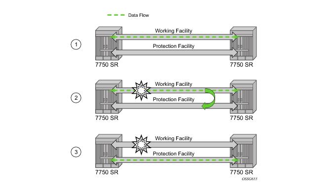
APS is designed to protect SONET/SDH equipment from linear unidirectional or bidirectional failures. The Network Elements (NEs) in a SONET/SDH network constantly monitor the health of the network. When a failure is detected, the network proceeds through a coordinated predefined sequence of steps to transfer (or switchover) live traffic to the backup facility (protection facility). This happens very quickly to minimize lost traffic. Traffic remains on the protection facility until the primary facility (working facility) fault is cleared, at which time the traffic may optionally be reverted to the working facility.
Working and protection circuits can be connected to a variety of types of network elements (ADMs, DACSes, ATM switches, routers) and serve as an access or network port providing one or more services or network interfaces to the router. APS-protected SONET/SDH ports may be further channelized, and may contain bundled channels MLPPP or IMA Bundle Protection Groups). The ports may be one of a variety of encapsulation types as supported by the MDA including PPP, ATM, FR and more. For a definitive description of the MDAs, port types, switching modes, bundles and encapsulations supported with APS see APS Applicability, Restrictions and Interactions .
The Figure 13 illustrates a Multi-Chassis APS group being used to protect against link, port, MDA, IOM or node failure.
Table 17 displays bits 5-8 of a K1 byte and K2 Bits 1-4 and the channel number code assignments.
Table 19 depicts the differences between the two standards.
An APS Protection Switching Byte (APS-PSB) failure indicates that the received K1 byte is either invalid or inconsistent. An invalid code defect occurs if the same K1 value is received for 3 consecutive frames (depending on the interface type (framer) used, the 7750 SR may not be able to strictly enforce the 3 frame check per GR-253 and G.783/G.841) and it is either an unused code or irrelevant for the specific switching operation. An inconsistent APS byte defect occurs when no three consecutive received K1 bytes of the last 12 frames are the same.
Table 20 outlines the steps that a bi-directional protection switching process will go through during a typical automatic switchover.
Note: In Annex B operation, all switch requests are for a switch from the primary section to the secondary section. Once a switch request clears normally, traffic is maintained on the section to which it was switched by making that section the primary section. The primary section may be working circuit 1 or working circuit 2 at any particular moment.
Figure 14 is an example in which the APS working circuit is connected to IOM-1 / MDA-1 and the protection circuit is connected to IOM-2 / MDA-1. In this example, assume that the working circuit is currently used to transmit and receive data.
The lockout of protection disables the use of the protection line. Since the tools>perform>aps>lockout command has the highest priority, a failed working line using the protection line is switched back to itself even if it is in a fault condition. No switches to the protection line are allowed when locked out.
The exercise command is only supported in the bi-directional mode of the 1+1 architecture. The exercise command is specified in the tools>perform>aps>force>exercise context and exercises the protection line by sending an exercise request over the protection line to the tail-end and expecting a reverse request response back. The switch is not actually completed during the exercise routine.
Table 21 shows the mapping between APS switching modes and MIB objects.
For details on MLFR/FRF.12 support with APS see the MLFR/FRF.12 Support of APS, BFD, and Mirroring Features section.
Table 23 displays examples of the port types that can be paired to provide APS protection. Both ports must be the same type and must be configured at the same speed.
Figure 15 displays an example of MLPPP termination on APS protected channelized OC-n/STM-n links. This example illustrates the following:
Figure 16 depicts an APS group between a digital access cross-connect system (DACS) and a pair of aggregation routers. At one end of the APS group both circuits (OC-3/STM-1 and/or OC-12/STM-4 links) are terminated on the DACS and at the other end each circuit is terminated on a different aggregation routers to provide protection against router failure. The MLPPP bundle operates between the BTS and the aggregation routers. At any one time only one of the two aggregation routers is actually terminating the MLPPP bundle (whichever aggregation router is processing the active APS circuit).
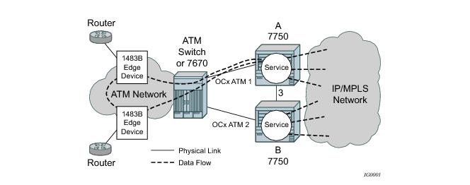
In Figure 17, service router A is connected to the ATM switch or 7670 through an OCx ATM 1 link. This link is configured as the working circuit. Service router B is connected to the same ATM switch or 7670 through an OCx ATM 2 link. This link is configured as the protection circuit.
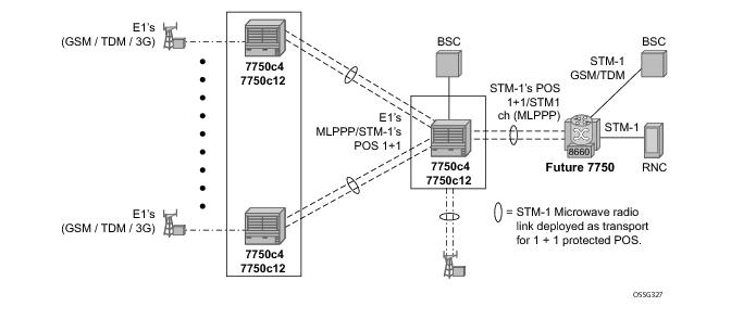
In the application show in Figure 19, 2G and 3G cell sites are aggregated into a Tier 2 or Tier 3 hub site before being backhauled to a Tier 1 site where the radio network controller (RNC) which terminates user calls is located. This application combines MC-APS on the RNC access side and pseudowire redundancy and pseudowire switching on the core network side. pseudowire switching is used in order to separate the routing domains between the access network and the core network.
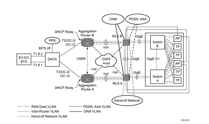
Figure 20 displays a RAN aggregation network deployment example. In this example Uni-dir 1+1 Sig+Data APS is being used.
As depicted in Figure 20, some APS-protected interfaces may require microwave radio transport.
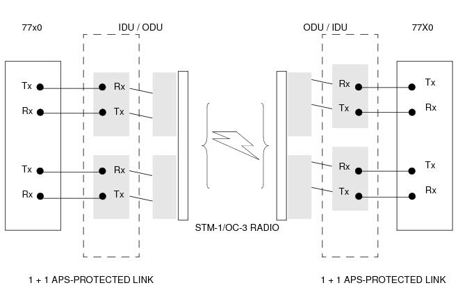
Figure 21 depicts APS-protected links between two routers that use Microwave transport. The radio equipment acts as a SONET section/ SDH regenerator section equipment, yet it implements Unidirectional APS-like processing to provide equipment protection on the local/remote radio sites respectively.
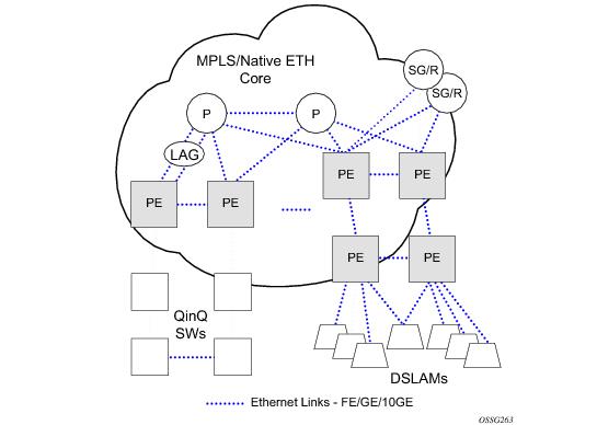
The example displayed in Figure 23 depicts a MPLS network that uses Ethernet interfaces in the core or as an access/handoff interfaces to connect to different kind of Ethernet enabled devices such as service gateway/routers, QinQ switches, DSLAMs or customer equipment.
Operators who are utilizing IOM3/IMM and above can tunnel the nearest-bridge at the port level using the tunnel-nearest-bridge command under the
config>port>ethernet>lldp>destmac (nearest-bridge) hierarchy. The dest-mac nearest-bridge must be disabled for tunneling to occur.
The implementation defaults to setting the port-id field in the LLDP OAMPDU to tx-local. This encodes the port-id field as ifIndex (sub-type 7) of the associated port. This is required to support some releases of SAM. SAM may use the ifIndex value to properly build the Layer Two Topology Network Map. However, this numerical value is difficult to interpret or readily identify the LLDP peer when reading the CLI or MIB value without SAM. Including the
port-desc option as part of the
tx-tlv configuration allows an ALU remote peer supporting
port-desc preferred display logic (11.0r1) to display the value in the port description TLV instead of the port-id field value. This does not change the encoding of the port-id field. That value continues to represent the ifIndex. In some environments, it may be important to select the specific port information that is carried in the port-id field. The operator has the ability to control the encoding of the port-id information and the associated subtype using the
port-id-subtype option. Three options are supported for the port-id-subtype:
tx-if-alias — Transmit the ifAlias String (subtype 1) that describes the port as stored in the IF-MIB, either user configured description or the default entry (ie 10/100/Gig ethernet SFP)
tx-if-name — Transmits the ifName string (subtype 5) that describes the port as stored in the IF-MIB, ifName info.
tx-local — The interface ifIndex value (subtype 7)
Based on the IEEE 802.1ax standard (formerly 802.3ad), Link Aggregation Groups (LAGs) can be configured to increase the bandwidth available between two
network devices, depending on the number of links installed. LAG also provides redundancy in the event that one or more links participating in the LAG fail. All physical links in a given LAG links combine to form one logical
interface.
The 7750 SR supports two modes of multiplexing RX/TX control for LACP: coupled and independent.
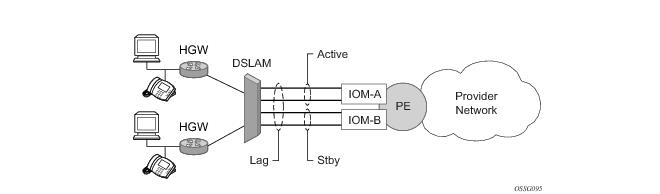
Figure 24 depicts how LAG in Active/Standby mode can be deployed towards a DSLAM access using sub-groups with auto-iom sub-group selection. LAG links are divided into two sub-groups (one per line card).
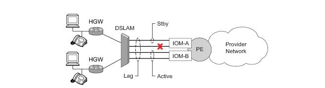
In case of a link failure, Figure 25 and
Figure 26, the switch over behavior ensures that all lag-members connected to the same IOM as failing link will become stand-by and lag-members connected to other IOM will become active. This way, QoS enforcement constraints are respected, while the maximum of available links is utilized.
Table 24 shows examples of rate/BW distributions based on the
adapt-qos mode used:
When the feature is enabled in the config>lag>access context, the queue allocation for SAPs on a LAG will be optimized and only one queuing set per ingress forwarding path (FP) is allocated instead of one per port.
When the feature is enabled in the config>lag>access context, the queue and virtual scheduler allocation will be optimized. Only one queuing set and one H-QoS virtual scheduler tree per SAP/encap group will be allocated per egress forwarding path (FP) instead of one set per each port of the LAG. In case of a link failure/recovery, egress traffic uses failover queues while the queues are moved over to a newly active link.
|
•
|
The LAG must have either per-link-hash enabled or all SAPs on the LAG must use per-service-hashing only and be of a type: VPLS SAP, i-VPLS SAP, or e-Pipe VLL or PBB SAP.
|
When the user performs the no form of this command on an interface, the interface inherits the system level configuration.
The default lbl-only hash option and the label-ip option with IPv4 payload is supported on all platforms and chassis modes. The
ip-only option with both IPv4 and IPv6 payloads as well as the lbl-ip option with IPv6 payload are only supported on IP interfaces on IOM3/IMM ports.
|
•
|
LAG port-type must be standard.
|
|
•
|
LAG access adapt-qos must be link or port-fair (for LAGs in mode access or hybrid).
|
|
−
|
discard – traffic for a given SAP/network interface will be dropped to protect other SAPs/network interfaces from being impacted by re-hashing these SAPs/network interfaces over remaining active LAG ports. Note: SAP/network interface status will not be affected when primary and secondary links are unavailable, unless an OAM mechanism that follows the data path hashing on egress is used and will cause a SAP/network interface to go down
|
|
−
|
per-link-hash – traffic for a given SAP/network interface will be re-hashed over remaining active ports of a LAG links using per-link-hashing algorithm. This behavior ensures SAP/network interfaces using this profile will be given available resources of other active LAG ports even if that means impacting other SAP/network interfaces on the LAG. The system will use the QoS configuration to provide fairness and priority if congestion is caused by the default-hash recovery.
|
|
•
|
LAG port-type must be standard.
|
|
•
|
LAG access adapt-qos must be link or port-fair (for LAGs in mode access or hybrid)
|
Per-service-hashing was introduced to ensure consistent forwarding of packets belonging to one service. The feature can be enabled using the [no]
per-service-hashing configuration option under
config>service>epipe and
config>service>vpls, valid for Epipe, VPLS, PBB Epipe, IVPLS and BVPLS. Chassis mode D is required.
A:Dut-B# tools dump map-to-phy-port lag 11 service 1
ServiceId ServiceName ServiceType Hashing Physical Link
---------- ------------- -------------- ----------------------- -------------
1 i-vpls per-service(if enabled) 3/2/8
A:Dut-B# tools dump map-to-phy-port lag 11 isid 1
ISID Hashing Physical Link
-------- ----------------------- -------------
1 per-service(if enabled) 3/2/8
A:Dut-B# tools dump map-to-phy-port lag 11 isid 1 end-isid 4
ISID Hashing Physical Link
-------- ----------------------- -------------
1 per-service(if enabled) 3/2/8
2 per-service(if enabled) 3/2/7
3 per-service(if enabled) 1/2/2
4 per-service(if enabled) 1/2/3
configure
subscr-mgmt
msap-policy <name>
sub-sla-mgmt
def-inter-dest-id use-top-queue
configure
port <port-id>
ethernet
access
egress
vport <name>
host-match dest <s-tag>
configure
service vpls <vpls-id>
sap lag-<id>
sub-sla-mgmt
mac-da-hashing
Note: This is only applicable to L2 ESM. In the case where this is configured AND Vport hashing is desired, the following order of evaluation will be executed:
In the first hash round for ECMP, the algorithm will parse down the label stack and once it hits the bottom it checks the next nibble. If the nibble value is 4 then it will assume it is an IPv4 packet. If the nibble value is 6 then it will assume it is an IPv6 packet. In both cases, the result of the label hash is fed into another hash along with source and destination address fields in the IP packet’s header. Otherwise, it will just use the label stack hash already calculated for the ECMP path selection.
When configuring the local and remote IP address for the BFD over LAG link sessions, the local-ip parameter should always match an IP address associated with the IP interface to which this LAG is bound. In addition, the
remote-ip parameter should match an IP address on the remote system and should also be in the same subnet as the
local-ip address. If the LAG bundle is re-associated with a different IP interface, the
local-ip and
remote-ip parameters should be modified to match the new IP subnet.
SROS routers support mixing different speed member ports in a single LAG. The LAG must be configured explicitly to allow mixed port-speed operation through the port-weight-speed command. The port-weight-speed defines both the lowest port speed for a member port in that LAG and the type of higher speed ports allowed to be mixed in the same LAG. For example, port-weight-speed 10 defines the minimum member port speed of 10GE and allows addition of any port that has a speed, which is a multiple of 10GE as long as the mix is supported by a given release, refer to specific Release Notes. Any LAG can be configured to support mixed port-speed operation.
|
•
|
It is recommended operators use weight-threshold instead of port-threshold to control LAG operational status. For example, when 10GE and 100GE ports are mixed in a LAG, each 10GE port will have a weight of 1, while each 100GE port will have a weight of 10. Note that the weight-threshold can also be used for LAGs not in mixed port-speed mode to allow common operational model (each port has a weight of 1 to mimic port-threshold and related configuration).
|
Alternatively, when access nodes does not support LACP, the power-off option can be used to enforce active/standby operation. In this case, the standby ports are
trx_disabled (power off transmitter) to prevent usage of the lag member by the access-node.Characteristics related to MC are:
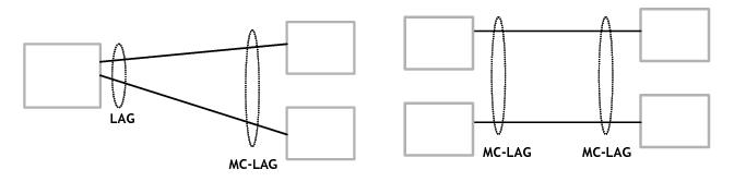
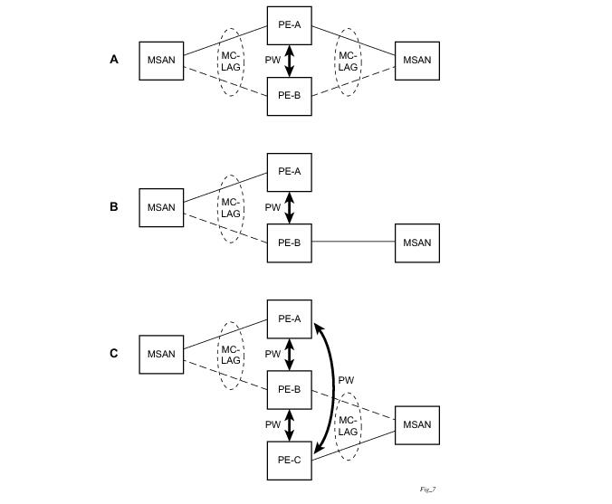
Figure 27 depicts different combinations of MC-LAG attachments supported. The supported configurations can be sub-divided into following sub-groups:
Refer to the 7750 SR OS Triple Play Guide for information about SRRP.
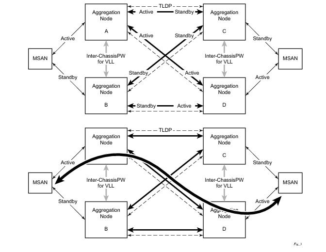
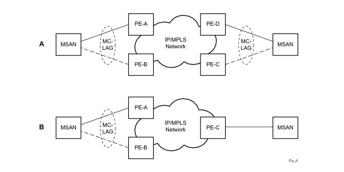
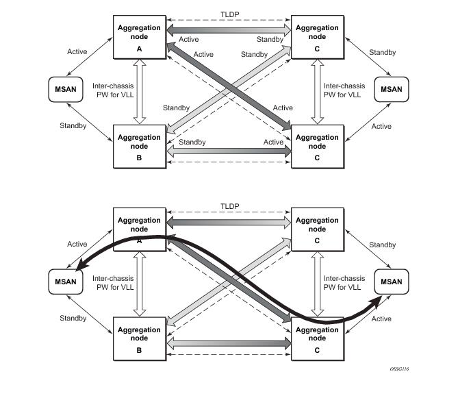
Figure 29 shows the connection between two multi-service access nodes (MSANs) across network based on Layer 2/3 VPN pseudo-wires. The connection between MSAN and a pair of PE routers is realized by MC-LAG. From MSAN perspective, redundant pair of PE routers acts as a single partner in LACP negotiation. At any point in time, only one of the routers has an active link(s) in a given LAG. The status of LAG links is reflected in status signaling of pseudo-wires set between all participating PEs. The combination of active and stand-by states across LAG links as well and pseudo-wires give only 1 unique path between pair of MSANs.
Note that the configuration in Figure 29 depicts one particular configuration of VLL connections based on MC-LAG, particularly the VLL connection where two ends (SAPs) are on two different redundant-pairs. In addition to this, other configurations are possible, such as:
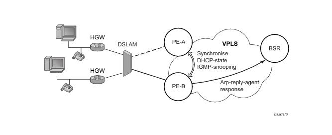
Figure 30 illustrates a network configuration where DSLAM is dual homed to pair of redundant PEs by using MC-LAG. Inside the aggregation network redundant-pair of PEs is connecting to VPLS service which provides reliable connection to single or pair of Broadband Service Routers (BSRs).
config>port>ethernet# info detail
----------------------------------------------
symbol-monitor
sd-threshold 5 multiplier 5
sf-threshold 3 multiplier 5
no shutdown
exit
show port 2/1/2 ethernet
===============================================================================
Ethernet Interface
===============================================================================
Description : 2/1/2
Interface : 2/1/2 Oper Speed : N/A
Link-level : Ethernet Config Speed : 1 Gbps
Admin State : down Oper Duplex : N/A
Oper State : down Config Duplex : full
Physical Link : No MTU : 9212
Single Fiber Mode : No Min Frame Length : 64 Bytes
IfIndex : 69271552 Hold time up : 0 seconds
Last State Change : 06/29/2014 05:04:12 Hold time down : 0 seconds
Last Cleared Time : N/A DDM Events : Enabled
Phys State Chng Cnt: 0
Configured Mode : network Encap Type : null
Dot1Q Ethertype : 0x8100 QinQ Ethertype : 0x8100
PBB Ethertype : 0x88e7
Ing. Pool % Rate : 100 Egr. Pool % Rate : 100
Ing. Pool Policy : n/a
Egr. Pool Policy : n/a
Net. Egr. Queue Pol: default
Egr. Sched. Pol : n/a
Auto-negotiate : true MDI/MDX : unknown
Oper Phy-tx-clock : not-applicable
Accounting Policy : None Collect-stats : Disabled
Acct Plcy Eth Phys : None Collect Eth Phys : Disabled
Egress Rate : Default Ingress Rate : Default
Load-balance-algo : Default LACP Tunnel : Disabled
Down-when-looped : Disabled Keep-alive : 10
Loop Detected : False Retry : 120
Use Broadcast Addr : False
Sync. Status Msg. : Disabled Rx Quality Level : N/A
Tx DUS/DNU : Disabled Tx Quality Level : N/A
SSM Code Type : sdh
Down On Int. Error : Disabled
CRC Mon SD Thresh : Disabled CRC Mon Window : 10 seconds
CRC Mon SF Thresh : Disabled
Sym Mon SD Thresh : 5*10E-5 Sym Mon Window : 10 seconds
Sym Mon SF Thresh : 5*10E-3 Tot Sym Mon Errs : 0
EFM OAM : Disabled EFM OAM Link Mon : Disabled
Configured Address : 8c:90:d3:a0:c7:42
Hardware Address : 8c:90:d3:a0:c7:42
Transceiver Data
Transceiver Status : not-equipped
===============================================================================
Traffic Statistics
===============================================================================
Input Output
-------------------------------------------------------------------------------
Octets 0 0
Packets 0 0
Errors 0 0
===============================================================================
===============================================================================
Port Statistics
===============================================================================
Input Output
-------------------------------------------------------------------------------
Unicast Packets 0 0
Multicast Packets 0 0
Broadcast Packets 0 0
Discards 0 0
Unknown Proto Discards 0
===============================================================================
===============================================================================
Ethernet-like Medium Statistics
===============================================================================
Alignment Errors : 0 Sngl Collisions : 0
FCS Errors : 0 Mult Collisions : 0
SQE Test Errors : 0 Late Collisions : 0
CSE : 0 Excess Collisns : 0
Too long Frames : 0 Int MAC Tx Errs : 0
Symbol Errors : 0 Int MAC Rx Errs : 0
In Pause Frames : 0 Out Pause Frames : 0
===============================================================================
The above configuration results in an SD threshold of 5*10E-5 (0.00005) and an SF threshold of 5*10E-3 (0.005) over the default 10 second window. If this port is a 1GbE port supporting symbol monitoring then the error rate is compared against 1,250,000,000 symbols (10 seconds worth of symbols on a 1GbE port 125,000,000). If the error count in the current 10 second sliding window is less than 62,500 then the error rate is below the signal degrade threshold and no action is taken. If the error count is between 62,501 and 6,250,000 then the error rate is above signal degrade but has not breached the signal failure signal threshold and a log event will be raised. If the error count is above 6,250,000 the signal failure threshold is crossed and the port will enter an operation state of down. Consider that this is a very simple example meant to demonstrate the function and not meant to be used as a guide for configuring the various thresholds and window times.
802.3ah Clause 57 (efm-oam) defines the Operations, Administration, and Maintenance (OAM) sub-layer, which provides mechanisms useful for monitoring link operation such as remote fault indication and remote loopback control. In general, OAM provides network operators the ability to monitor the health of the network and quickly determine the location of failing links or fault conditions.
efm-oam described in this clause provides data link layer mechanisms that complement applications that may reside in higher layers.
The following efm-oam functions are supported:
When the efm-oam protocol fails to negotiate a peer session or encounters a protocol failure following an established session the
Port State will enter the
Link Up condition. This port state is used by many protocols to indicate the port is administratively UP and there is physical connectivity but a protocol, such as
efm-oam, has caused the ports operational state to enter a DOWN state. A reason code has been added to help discern if the
efm-oam protocol is the underlying reason for the Link Up condition.
show port
===============================================================================
Ports on Slot 1
===============================================================================
Port Admin Link Port Cfg Oper LAG/ Port Port Port C/QS/S/XFP/
Id State State MTU MTU Bndl Mode Encp Type MDIMDX
-------------------------------------------------------------------------------
1/1/1 Down No Down 1578 1578 - netw null xcme
1/1/2 Down No Down 1578 1578 - netw null xcme
1/1/3 Up Yes Link Up 1522 1522 - accs qinq xcme
1/1/4 Down No Down 1578 1578 - netw null xcme
1/1/5 Down No Down 1578 1578 - netw null xcme
1/1/6 Down No Down 1578 1578 - netw null xcme
# show port 1/1/3
===============================================================================
Ethernet Interface
===============================================================================
Description : 10/100/Gig Ethernet SFP
Interface : 1/1/3 Oper Speed : N/A
Link-level : Ethernet Config Speed : 1 Gbps
Admin State : up Oper Duplex : N/A
Oper State : down Config Duplex : full
Reason Down : efmOamDown
Physical Link : Yes MTU : 1522
Single Fiber Mode : No Min Frame Length : 64 Bytes
IfIndex : 35749888 Hold time up : 0 seconds
Last State Change : 12/18/2012 15:58:29 Hold time down : 0 seconds
Last Cleared Time : N/A DDM Events : Enabled
Phys State Chng Cnt: 1
Configured Mode : access Encap Type : QinQ
Dot1Q Ethertype : 0x8100 QinQ Ethertype : 0x8100
PBB Ethertype : 0x88e7
Ing. Pool % Rate : 100 Egr. Pool % Rate : 100
Ing. Pool Policy : n/a
Egr. Pool Policy : n/a
Net. Egr. Queue Pol: default
Egr. Sched. Pol : n/a
Auto-negotiate : true MDI/MDX : unknown
Oper Phy-tx-clock : not-applicable
Accounting Policy : None Collect-stats : Disabled
Acct Plcy Eth Phys : None Collect Eth Phys : Disabled
Egress Rate : Default Ingress Rate : Default
Load-balance-algo : Default LACP Tunnel : Disabled
Down-when-looped : Disabled Keep-alive : 10
Loop Detected : False Retry : 120
Use Broadcast Addr : False
Sync. Status Msg. : Disabled Rx Quality Level : N/A
Tx DUS/DNU : Disabled Tx Quality Level : N/A
SSM Code Type : sdh
Down On Int. Error : Disabled
CRC Mon SD Thresh : Disabled CRC Mon Window : 10 seconds
CRC Mon SF Thresh : Disabled
Configured Address : d8:ef:01:01:00:03
Hardware Address : d8:ef:01:01:00:03
The operator also has the opportunity to decouple the efm-oam protocol from the port state and operational state. In cases where an operator wants to remove the protocol, monitor the protocol only, migrate, or make changes the
ignore-efm-state can be configured in the
port>ethernet>efm-oam context. When the
ignore-efm-state command is configured on a port the protocol continues as normal. However, ANY failure in the protocol state machine (discovery, configuration, time-out, loops, etc.) will not impact the port on which the protocol is active and the optional ignore command is configured. There will only be a protocol warning message if there are issues with the protocol. The default behavior when this optional command is not configured means the port state will be affected by any
efm-oam protocol fault or clear conditions. Adding and removing this optional ignore command will immediately represent the
Port State and
Oper State based on the active configuration. For example, if the
ignore-efm-state is configured on a port that is exhibiting a protocol error that protocol error does not affect the port state or operational state and there is no
Reason Down code. If the
ignore-efm-state is removed from a port with an existing
efm-oam protocol error, the port will transition to
Link UP,
Oper Down with the reason code
efmOamDown.
A peer processing the Information OAMPDU can take a configured action when one or more of these Flag fields are set. By default, receiving a set value for any of the Flag fields will cause the local port to enter the previous mentioned Link Up port state and an event will be logged. If this default behavior is not desired, the operator may choose to log the event without affecting the local port. This is configurable per Flag field using the options under
config>port>ethernet>efm-oam>peer-rdi-rx.
Link monitoring can be enabled for three types of frame errors; errored-frame,
errored-frame-period and
errored-frame-seconds. The
errored-frame monitor is the number of frame errors compared to the threshold over a window of time. The
errored-frame-period monitor is the number of frame errors compared to the threshold over a window of number of received packets. This window is checked once per second to see if the window parameter has been reached. The
errored-frame-seconds monitor is the number of errored seconds compared to the threshold over a window of time. An errored second is any second with a single frame error.
Each frame error monitor functions independently of other monitors. Each of monitor configuration includes an optional signal degrade threshold sd-threshold, a signal failure threshold
sf-threshold, a
window and the ability to communicate failure events to the peer by setting a Flag field in the Information OAMPDU or the generation of the Event Notification OAMPDU,
event-notification. The parameters are uniquely configurable for each monitor.
A degraded condition is raised when the configured signal degrade sd-threshold is reached. This provides a first level log only action indicating a link could become unstable. This event does not affect the port state. The critical failure condition is raised when the configured
sf-threshold is reached. By default, reaching the signal failure threshold will cause the port to enter the
Link Up condition unless the local signal failure
local-sf-action has been modified to a
log-only action. Signal degrade conditions for a monitor in signal failed state will be suppressed until the signal failure has been cleared.
As discussed earlier, the Information OAMPDU conveys link information using the Flags field; dying gasp, critical link and link fault. This method of communication has a number of significant advantages over the Event Notification OAMPDU. The Information OAMPDU is sent at every configured transmit-interval. This will allow the most recent information to be sent between peers, a critical requirement to avoid asymmetrical forwarding conditions. A second major advantage is interoperability with devices that do not support Link Monitoring and vendor interoperability. This is the lowest common denominator that offers a robust communication to convey link event information. Since the Information OAMPDU is already being sent to maintain the peering relationship this method of communication adds no additional overhead. The l
ocal-sf-action options allow the dying gasp and critical event flags to be set in the Information OAMPDU when a signal failure threshold is reached. It is suggested that this be used in place of or in conjunction with Event Notification OAMPDU.
A burst of between one and five Event Notification OAMPDU packets may be sent. By default, only a single Event Notification OAMPDU is generated, but this value can be changed under the local-sf-action context. An Event Notification OAMPDU will only be processed if the peer had previously advertised the EV capability. The EV capability is an indication the remote peer supports link monitoring and may send the Event Notification OAMPDU.
Symbol error, errored-symbols, monitoring is also supported but requires specific hardware revisions and the appropriate code release. The symbol monitor differs from than the frame error monitors. Symbols represent a constant load on the Ethernet wire whether service frames are present or not. This means the optional signal degrade threshold
sd-threshold has an additional purpose when configured as part of the symbol error monitor. When the signal degrade threshold is not configured, the symbol monitor acts similar to the frame error monitors, requiring manual intervention to clear a port that has been operationally affected by the monitor. When the optional signal degrade threshold is configured, it again represents the first level warning. However, it has an additional function as part of the symbol monitor. If a signal failure event has been raised, the configured signal degrade threshold becomes the equivalent to a lowering threshold. If a subsequent window does not reach the configured signal degrade threshold then the previous event will be cleared and the previously affected port will be returned to service without operator intervention. This return to service will automatically clear any previously set Information OAMPDU Flags fields set as a result of the signal failure threshold. The Event Notification OAMPDU will be generated with the symbol error Link TLV that contains an error count less than the threshold. This will indicate to the peer that initial problem has been resolved and the port should be returned to service.
The errored-symbol window is a measure of time that is automatically converted into the number of symbols for that specific medium for that period of time. The standard MIB entries “dot3OamErrSymPeriodWindowHi” and “dot3OamErrSymPeriodWindowLo” are marked as read-only instead of read-write. There is now way to directly configure these values. The configuration of the
window will convert the time and program those two MIB values in an appropriate manner. Both the configured
window and the number of symbols will be displayed under the
show port port-id ethernet efm-oam command.
show port 1/1/1 ethernet efm-oam
===============================================================================
Ethernet Oam (802.3ah)
===============================================================================
Admin State : up
Oper State : link fault
Mode : active
Pdu Size : 1518
Config Revision : 0
Function Support : LB
Transmit Interval : 1000 ms
Multiplier : 5
Hold Time : 0
Tunneling : false
Loop Detected : false
Grace Tx Enable : true (inactive)
No Peer Information Available
Loopback State : None
Loopback Ignore Rx : Ignore
Ignore Efm State : false
Link Monitoring : disabled
Peer RDI Rx
Critical Event : out-of-service
Dying Gasp : out-of-service
Link Fault : out-of-service
Event Notify : log-only
Local SF Action Discovery
Event Burst : 1 Ad Link Mon Cap : yes
Port Action : out-of-service
Dying Gasp : disabled
Critical Event : disabled
Errored Frame Errored Frame Period
Enabled : no Enabled : no
Event Notify : enabled Event Notify : enabled
SF Threshold : 10 SF Threshold : 1
SD Threshold : disabled (0) SD Threshold : disabled (0)
Window : 10 ds Window : 1488095 frames
Errored Symbol Period Errored Frame Seconds Summary
Enabled : no Enabled : no
Event Notify : enabled Event Notify : enabled
SF Threshold : 1 SF Threshold : 1
SD Threshold : disabled (0) SD Threshold : disabled (0)
Window (time) : 10 ds Window : 600 ds
Window (symbols) : 125000000
===============================================================================
Active Failure Ethernet OAM Event Logs
===============================================================================
Number of Logs : 0
===============================================================================
===============================================================================
Ethernet Oam Statistics
===============================================================================
Input Output
-------------------------------------------------------------------------------
Information 0 0
Loopback Control 0 0
Unique Event Notify 0 0
Duplicate Event Notify 0 0
Unsupported Codes 0 0
Frames Lost 0
===============================================================================
A clear command “
clear port port-id ethernet efm-oam events [local | remote]” has been added to clear port affecting events on the local node on which the command is issued. When the optional [
local | remote] options are omitted, both local and remote events will be cleared for the specified port. This command is not specific to the link monitors as it clears all active events. When local events are cleared, all previously set Information OAMPDU Flag fields will be cleared regardless of the cause the event that set the Flag field.
Local and remote efm-oam port events are stored in the efm-oam event logs. These logs maintain and display active and cleared signal failure degrade events. These events are interacting with the efm-oam protocol. This logging is different than the time stamped events for information logging purposes included with the system log. To view these events, the event-log option has been added to the s
how port port-id ethernet efm-oam command. This includes the location, the event type, the counter information or the decoded Network Event TLV information, and if the port has been affected by this active event. A maximum of 12 port events will be retained. The first three indexes are reserved for the three Information Flag fields, dying gasp, critical link, and link fault. The other nine indexes will maintain the current state for the various error monitors in a most recent behavior and events can wrap the indexes, dropping the oldest event.
show port 1/2/1 ethernet efm-oam event-logs
===============================================================================
Active Failure Ethernet OAM Event Logs
===============================================================================
Log Index : 4
Event Time Reference : 0d 07:01:45
Location : remote
Type : Errored Frame
Window : 50
Threshold : 100
Value : 100
Running Total : 100
Event Total : 1
Port Affecting : yes
-------------------------------------------------------------------------------
Number of Logs : 1
===============================================================================
===============================================================================
Active Degraded Ethernet OAM Event Logs
===============================================================================
Number of Logs : 0
===============================================================================
===============================================================================
Cleared Failure Ethernet OAM Event Logs
===============================================================================
Log Index : 2
Event Time Reference : 0d 06:59:08
Location : remote
Type : Dying Gasp
Event Total : 16
-------------------------------------------------------------------------------
Number of Logs : 1
===============================================================================
===============================================================================
Cleared Degraded Ethernet OAM Event Logs
===============================================================================
Number of Logs : 0
===============================================================================
SRoS supports the vendor specific soft reset graceful recovery of efm-oam through the configuration of grace-tx-enable under the
config>system>ethernet>efm-oam and the
config>port>ethernet>efm-oam contexts. This feature is not enabled by default. When this functionality is enabled the efm-oam protocol does not enter a non-operational state when both nodes understand the grace function. The ports associated with the hardware that has successfully executed the soft reset will clear all local and remote events. The peer that understands the graceful restart procedure for efm-oam will clear all remote events that it received from the peer that undergone the soft reset. The local events will not be cleared on the peer that has not undergone soft reset. Again, the Information OAMPDU Flag fields are critical in propagating the local event to the peer. Remember, the Event Notification OAMPDU will not be sent because it is only sent on the initial raise.
The 7750 SR routers support 802.3ah. Customers who subscribe to Epipe service treat the Epipe as a wire, so they demand the ability to run 802.3ah between their devices which are located at each end of the Epipe.
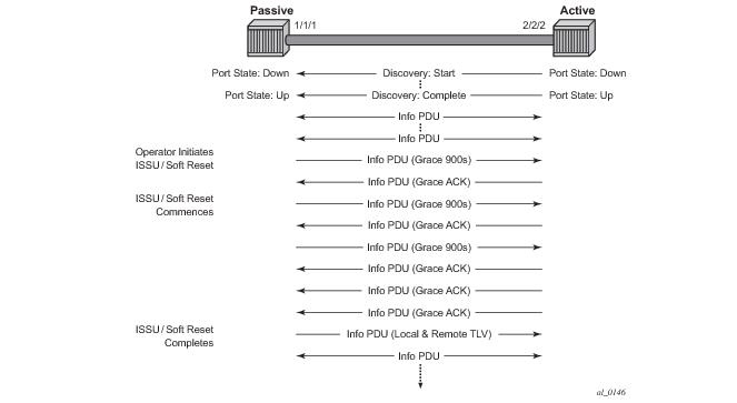
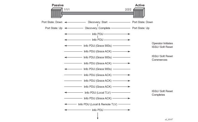
The new command grace-tx-enable has been introduced to enable this functionality. This command exists at two levels of the hierarchy, system level and port level. By default this functionality is enabled on the port. At the system level this command defaults to disabled. In order to enable this functionality both the port and the system commands must be enabled. If either is not enabled then the combination will not allow those ports to generate the vendor specific Grace TLV. This functionality must be enabled at both the system and port level prior to the ISSU or soft reset function. If this is enabled during a soft reset or after the ISSU function is already in progress it will have no affect during that window. Both Passive and Active 802.3ah OAM peers can generate the Grace TVL as part of the informational PDU.
In Figure 31 the Active node is experiencing the ISSU function on a node that supports soft reset capabilities.
show system information
===============================================================================
System Information
===============================================================================
System Name : ystem-name
System Type : 7750 SR-12
System Version : 11.0r4
System Contact :
System Location :
System Coordinates :
System Active Slot : A
System Up Time : 62 days, 20:29:48.96 (hr:min:sec)
…snip…
EFM OAM Grace Tx Enable: False
===============================================================================
Grace Tx Enable has two enable states with the current state in brackets to the right.
show port 1/2/1 ethernet efm-oam
===============================================================================
Ethernet Oam (802.3ah)
===============================================================================
Admin State : up
Oper State : operational
Mode : active
Pdu Size : 1514
Config Revision : 0
Function Support : LB
Transmit Interval : 100 ms
Multiplier : 2
Hold Time : 0
Tunneling : false
Loop Detected : false
Grace Tx Enable : true (active)
Peer Mac Address : 00:16:4d:16:5e:40
Peer Vendor OUI : 00:16:4d
Peer Vendor Info : 00:00:00:00
Peer Mode : active
Peer Pdu Size : 1514
Peer Cfg Revision : 0
Peer Support : LB
Peer Grace Rx : false
Loopback State : None
Loopback Ignore Rx : Ignore
Ignore Efm State : false
===============================================================================
Ethernet Oam Statistics
===============================================================================
Input Output
-------------------------------------------------------------------------------
Information 0 697
Loopback Control 0 0
Unsupported Codes 0 0
Frames Lost 0
===============================================================================
show port 3/2/1 ethernet efm-oam
===============================================================================
Ethernet Oam (802.3ah)
===============================================================================
Admin State : up
Oper State : operational
Mode : active
Pdu Size : 1514
Config Revision : 0
Function Support : LB
Transmit Interval : 100 ms
Multiplier : 2
Hold Time : 0
Tunneling : false
Loop Detected : false
Grace Tx Enable : true (inactive)
Peer Mac Address : 00:16:4d:95:ea:2a
Peer Vendor OUI : 00:16:4d
Peer Vendor Info : 00:00:00:00
Peer Mode : active
Peer Pdu Size : 1514
Peer Cfg Revision : 0
Peer Support : LB
Peer Grace Rx : true
Loopback State : None
Loopback Ignore Rx : Ignore
Ignore Efm State : false
===============================================================================
Ethernet Oam Statistics
===============================================================================
Input Output
-------------------------------------------------------------------------------
Information 24488 50984
Loopback Control 1784 4859
Unsupported Codes 0 0
Frames Lost 0
===============================================================================
|
•
|
The 7750 SR must contend with MTU limitations at many service points. The physical (access and network) port, service, and SDP MTU values must be individually defined.
|
|
•
|
MTU values should not be modified frequently.
|
Table 25 displays the default MTU values which are dependent upon the (sub-) port type, mode, and encapsulation.
Since ALA-A uses Dot1q encapsulation, the SAP MTU must be set to 1518 to be able to accept a 1514 byte service frame (see
Table 25 for MTU default values). Each SDP MTU must be set to at least 1514 as well. If
ALA-A’s network port (2/1/1) is configured as an Ethernet port with a GRE SDP encapsulation type, then the MTU value of network ports 2/1/1 and 3/1/1 must
each be at least 1556 bytes (1514 MTU + 28 GRE/Martini + 14 Ethernet). Finally, the MTU of
ALA-B’s SAP (access port 4/1/1) must be at least 1514, as it uses null encapsulation.
When a line card/CMA/MDAXCM/XMA is installed in a preprovisioned slot, the device detects discrepancies between the preprovisioned line card/CMA/MDAXCM/XMA type configurations and the types actually installed. Error messages display if there are inconsistencies and the card will not
initialize.
With the introduction of SFM5-12e and the mini-SFM5-12e, a new tools command (set-fabric-speed) was added to set the fabric operating speed. (tools command does not apply to SFM4-12e fabric-speed-a). 7750 SR-7 and 7750 SR-12 support f
abric-speed-b.
The 7750 SR-12e chassis defaults to the fabric-speed-a parameter when initially deployed with SFM5-12e. The
fabric-speed-a parameter operates at 200GB per slot which permits a mixture of FP2/FP3 based cards to co-exist.
The fabric-speed-b parameter enables the 7750 SR-12e to operate at up to 400 Gb/s, for which all cards in the 7750 SR-12e are required to be T3 based (FP3 IMM and/or IOM3-XP-C). The system will not support any FP2 based cards when the chassis is set to
fabric-speed-b.
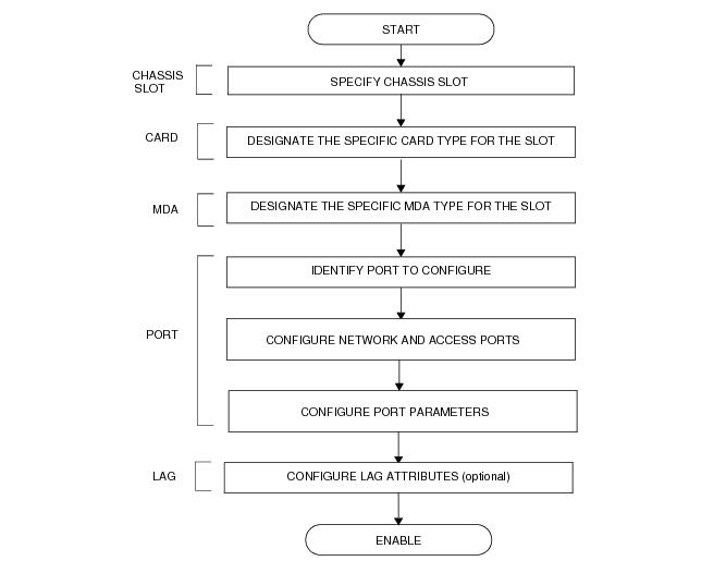
Figure 34 displays the process to provision chassis slots, line cards, MDAs, and ports.
|
•
|
A card and MDA installed in an unprovisioned slot remain administratively and operationally down until the card type and MDA is specified.
|


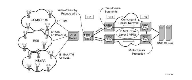 Figure 19: MC-APS with ATM VLL RedundancyIn the application show in Figure 19, 2G and 3G cell sites are aggregated into a Tier 2 or Tier 3 hub site before being backhauled to a Tier 1 site where the radio network controller (RNC) which terminates user calls is located. This application combines MC-APS on the RNC access side and pseudowire redundancy and pseudowire switching on the core network side. pseudowire switching is used in order to separate the routing domains between the access network and the core network.Figure 20 displays a RAN aggregation network deployment example. In this example Uni-dir 1+1 Sig+Data APS is being used.Figure 20: Mobile RAN with Microwave Transport ExampleAs depicted in Figure 20, some APS-protected interfaces may require microwave radio transport. Figure 21 depicts APS-protected links between two routers that use Microwave transport. The radio equipment acts as a SONET section/ SDH regenerator section equipment, yet it implements Unidirectional APS-like processing to provide equipment protection on the local/remote radio sites respectively.Figure 21: 1+1 APS Protected Microwave SDH TransportFigure 22: LLDP Internal Architecture for a Network NodeFigure 23: Generic Customer Use Case For LLDPThe example displayed in Figure 23 depicts a MPLS network that uses Ethernet interfaces in the core or as an access/handoff interfaces to connect to different kind of Ethernet enabled devices such as service gateway/routers, QinQ switches, DSLAMs or customer equipment.Operators who are utilizing IOM3/IMM and above can tunnel the nearest-bridge at the port level using the tunnel-nearest-bridge command under the config>port>ethernet>lldp>destmac (nearest-bridge) hierarchy. The dest-mac nearest-bridge must be disabled for tunneling to occur.The implementation defaults to setting the port-id field in the LLDP OAMPDU to tx-local. This encodes the port-id field as ifIndex (sub-type 7) of the associated port. This is required to support some releases of SAM. SAM may use the ifIndex value to properly build the Layer Two Topology Network Map. However, this numerical value is difficult to interpret or readily identify the LLDP peer when reading the CLI or MIB value without SAM. Including the port-desc option as part of the tx-tlv configuration allows an ALU remote peer supporting port-desc preferred display logic (11.0r1) to display the value in the port description TLV instead of the port-id field value. This does not change the encoding of the port-id field. That value continues to represent the ifIndex. In some environments, it may be important to select the specific port information that is carried in the port-id field. The operator has the ability to control the encoding of the port-id information and the associated subtype using the port-id-subtype option. Three options are supported for the port-id-subtype:tx-if-alias — Transmit the ifAlias String (subtype 1) that describes the port as stored in the IF-MIB, either user configured description or the default entry (ie 10/100/Gig ethernet SFP)tx-if-name — Transmits the ifName string (subtype 5) that describes the port as stored in the IF-MIB, ifName info.tx-local — The interface ifIndex value (subtype 7)Based on the IEEE 802.1ax standard (formerly 802.3ad), Link Aggregation Groups (LAGs) can be configured to increase the bandwidth available between two network devices, depending on the number of links installed. LAG also provides redundancy in the event that one or more links participating in the LAG fail. All physical links in a given LAG links combine to form one logical interface.LAGs must be statically configured or formed dynamically with Link Aggregation Control Protocol (LACP). The optional marker protocol described in IEEE 802.1ax is not implemented. LAGs can be configured on network and access ports.LACP enhancements allow active lag-member selection based on particular constrains. The mechanism is based on the IEEE 802.1ax standard so interoperability is ensured.To use LACP on a given LAG, operator must enable LACP on the LAG including, if desired, selecting non-default LACP mode: active/passive and configuring administrative key to be used (configure lag lacp). IN addition an operator can configure desired LACP transmit interval (configure lag lacp-xmit-interval).The 7750 SR supports two modes of multiplexing RX/TX control for LACP: coupled and independent.When the power-off is selected as the standby-signaling, the selection-criteria best-port can be used.Figure 24 depicts how LAG in Active/Standby mode can be deployed towards a DSLAM access using sub-groups with auto-iom sub-group selection. LAG links are divided into two sub-groups (one per line card).In case of a link failure, Figure 25 and Figure 26, the switch over behavior ensures that all lag-members connected to the same IOM as failing link will become stand-by and lag-members connected to other IOM will become active. This way, QoS enforcement constraints are respected, while the maximum of available links is utilized.Figure 25: LAG on Access InterconnectionFigure 26: LAG on Access Failure Switchover
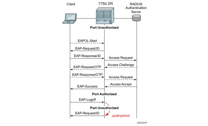
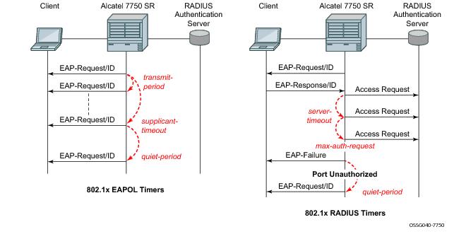
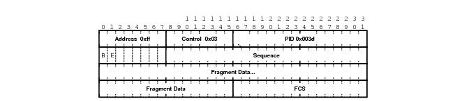

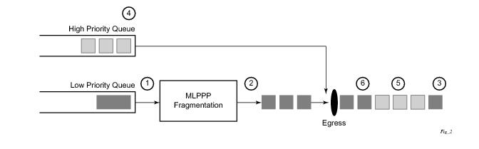
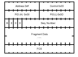
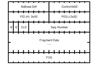
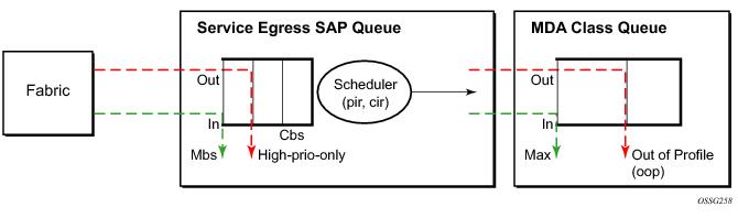
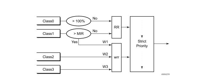
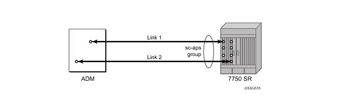
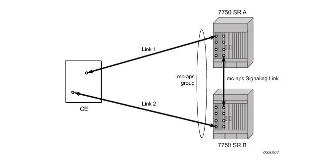
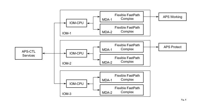
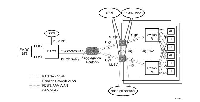 .
.