For feedback and comments:
documentation.feedback@alcatel-lucent.com

Table of Contents Previous Next Index PDF


Configuring Physical Ports with CLI
This section provides information to configure cards, MDAs, and ports.
Topics in this section include:
Preprovisioning Guidelines
7750 SR routers have at least two ports, either located on SF/CPM modules on the CCM or integrated into the chassis (on the 7750 SR-c4 models), a console port and an auxiliary port, to connect terminals to the router.
Configure parameters from a system console connected to a 7750 SR console port, using Telnet to access a 7750 SR remotely or SSH to open a secure shell connection.
 
Predefining Entities
In order to initialize a card, the chassis slot, line card type, and MDA type must match the preprovisioned parameters. In this context, preprovisioning means to configure the entity type (such as the line card type, MDA type, port, and interface) that is planned for a chassis slot, line card, or MDA. Preprovisioned entities can be installed but not enabled or the slots can be configured but remain empty until populated. Provisioning means that the preprovisioned entity is installed and enabled.
You can:
 
Preprovisioning a Port
Before a port can be configured, the slot must be preprovisoned with an allowed card type and the MDA must be preprovisioned with an allowed MDA type.
Some recommendations to configure a port include:
An encapsulation type may be specified in order to distinguish services on the port or channel. Encapsulation types are not required for network ports.
To configure an Ethernet access port, refer to .
SONET/SDH can be used only when configuring an OC-3, OC-12, OC-48, OC-192, and OC-768 SONET paths on an appropriate MDA.
To configure a SONET path, refer to Configuring SONET/SDH Port Parameters .
Configure a network port or channel to participate in the service provider transport or infrastructure network.
Accounting policies can only be associated with network ports/channels and Service Access Ports (SAPs). Accounting policies are configured in the config>log> accounting-policy context.
To configure an Ethernet network port, refer to .
 
Maximizing Bandwidth Use
Once ports are preprovisioned, Link Aggregation Groups (LAGs), multilink-bundles (IMA), or Bundle Protection Groups (for example IMA BPGrps), can be configured to increase the bandwidth available between two nodes. All physical links or channels in a given LAG combine to form one logical connection. A LAG also provides redundancy in case one or more links that participate in the LAG fail. For command syntax, see Configuring Multilink PPP Bundles . To configure channelized port for TDM, refer to section Configuring Channelized Ports . To configure channelized port for Sonet/SDH high speed channels (ASAP MDAs only), refer to Configuring SONET/SDH Port Parameters .
Basic Configuration
The most basic configuration must have the following:
Specify MCM slot for 7750 SR-c4 and SR-c12 only (not required for CMA)
Specify MCM type 7750 SR-c4 and SR-c12 only (must be an allowed MCM type)
Identify MDA slot.
Specify MDA (must be an allowed MDA type).
The following example displays some card configurations:
ALA-A>config# info
#------------------------------------------
# Card Configuration
#------------------------------------------
	card 1
        card-type iom-20g
        mda 1
            mda-type m60-10/100eth-tx
        exit
        mda 2
            mda-type m60-10/100eth-tx
        exit
    exit
    card 2
        card-type iom-20g
        mda 1
            mda-type m10-1gb-sfp
        exit
        mda 2
            mda-type m10-1gb-sfp
        exit
    exit
    card 3
        card-type iom-20g
        mda 1
            mda-type m12-ds3
        exit
        mda 2
            mda-type m12-ds3
        exit
    exit
    card 8
        card-type iom-20g
        mda 1
            mda-type m8-oc12/3-sfp
        exit
        mda 2
            mda-type m16-oc12/3-sfp
        exit
    exit
#--------------------------------------------------
echo "Card Configuration"
#--------------------------------------------------
    card 1
        card-type iom-xp
        mcm 1
            mcm-type mcm-xp
        exit
        mcm 3
            mcm-type mcm-xp
        exit
        mda 1
            mda-type m60-10/100eth-tx
        exit
        mda 3
            mda-type m4-atmoc12/3-sfp
        exit
        mda 5
            mda-type c8-10/100eth-tx
        exit
        mda 6                         
            mda-type c1-1gb-sfp
        exit
        mda 7
            mda-type c8-chds1
        exit
        mda 8
            mda-type c4-ds3
        exit
    exit
#--------------------------------------------------
ALA-A> config# 
#--------------------------------------------------
echo "Card Configuration "
#--------------------------------------------------
card 1
card-type iom-c4-xp
mcm 1
mcm-type mcm-v1
exit
mcm 3
mcm-type mcm-xp
exit
mda 1
mda-type m60-10/100eth-tx
exit
mda 3
mda-type m4-atmoc12/3-sfp
exit
exit
#--------------------------------------------------
ALA-A> config#
configure
    card 2
        card-type iom3-xp
        mda 1
            mda-type isa-tms
            no shutdown
        exit
        mda 2
            mda-type isa-tms
            no shutdown
        exit
        no shutdown
    exit
exit
Common Configuration Tasks
The following sections are basic system tasks that must be performed.
Configuring Cards and MDAs
Card configurations include a chassis slot designation. To configure the Versatile Service Module, refer to the Versatile Service Module section of the 7750 SR Services Guide.
The following example displays a card and MDA configuration:
A:ALA-B>config>card# info
----------------------------------------------
	 card-type iom-20g
        mda 1
            mda-type m10-1gb-sfp
        exit
        mda 2
            mda-type m10-1gb-sfp
        exit
----------------------------------------------
A:ALA-B>config>card#
Configuring Cards, MDA Carrier Modules (MCMs) and Media Dependent Adapters (MDAs)
Card configurations must include a chassis slot designation. A slot must be preconfigured with the type of cards, MCMs, and MDAs which are allowed to be provisioned.
Note: Output for Media Dependent Adapters (MDAs) show an “m” in the mda-type description, for example, m60-eth10/100-tx.
Use the config > info command to display card configuration information:
A:7710-3>config# info
. . .
#------------------------------------------
echo "Card Configuration"
#------------------------------------------
card 1
card-type iom-xp
mcm 1
mcm-type mcm-xp
exit
mcm 3
mcm-type mcm-xp
exit
mda 1
mda-type m60-eth10/100-tx
exit
mda 3
mda-type m60-eth10/100-tx
exit
exit
 
Configuring Cards and Compact Media Adapters (CMAs)
Card configurations must include a chassis slot designation. A slot must be preconfigured with the type of cards and CMAs which are allowed to be provisioned.
Note: Compact Media Adapters (CMAs) are configured using the MDA command. Output for Compact Media Adapter MDAs show a “c” in the mda-type description, for example,
c8-10/100eth-tx.
Use the config > info command to display card configuration information:
A:7710-3>config# info
. . .
#------------------------------------------
echo "Card Configuration"
#------------------------------------------
card 1
card-type iom-xp
mda 5
mda-type c8-10/100eth-tx
exit
mda 6
mda-type c8-10/100eth-tx
exit
exit
#------------------------------------------
 
Configuring Forwarding Plane Parameters
The following output provides a forwarding plane configuration. The fp command is not allowed on iom-1 or iom-2 types. An error message appears when the command is executed on an incorrect IOM type:
MINOR: CLI This command is not supported for iom2-20g.
 
*A:Dut-C# configure card 10
*A:Dut-C>config>card# info
----------------------------------------------
        card-type iom3-xp
        fp 1
            ingress
                mcast-path-management
                    bandwidth-policy "BWP"
                    no shutdown
                exit
            exit
        exit
        mda 1
            mda-type m1-10gb
            ingress
                mcast-path-management
                    bandwidth-policy "BWP"
                    no shutdown
                exit
            exit
        exit
        mda 2
            mda-type m2-10gb-xfp
            ingress
                mcast-path-management
                    bandwidth-policy "BWP"
                    no shutdown
                exit
            exit
        exit
----------------------------------------------
*A:Dut-C>config>card# exit
 
Configuring MDA/CMA Access and Network Pool Parameters
MDA-level pools are used by ingress network queues. Network policies can be applied (optional) to create and edit QoS pool resources on egress network ports, channels, and ingress MDAs. Network-queue and slope policies are configured in the config>qos context.
The following example displays an MDA pool configuration:
A:ALA-B>config>card>mda# info
----------------------------------------------
            mda-type m10-1gb-sfpcx
            network
                egress
                    pool
                        slope-policy "B"
                    exit
                exit
            exit
            access
                ingress
                    pool
                        resv-cbs 50
                        slope-policy "A"
                    exit
                exit
            exit
----------------------------------------------
A:ALA-B>config>card>mda#
 
Configuring MDA Policies for Named Pools Mode
Network ingress queues can use either MDA ingress named pools or ingress default pools but not port named pools. In the case with an IOM with multiple MDAs sharing the same buffer space (iom3-xp, iom-10g), network ingress queues will use only the MDA 1 named pools. Even if named pools are configured for MDA 2, they will not be used by network ingress queues. Network ingress queues configured to use MDA2 named pools will be considered pool orphaned. To check for orphan queues, use the command “show mda <mda> qos ingress orphaned-queues”.
SAP shared queues use by default the SAP shared pool; a system reserved buffer pool. Shared queues can be configured to use MDA named pools. Shared queues cannot be configured to use port pools since they are not port specific queues. In case a shared queue is configured to use a port named pool, the queue will be considered orphan and will get buffers from access ingress default pool.
For complete QoS configuration details reference the Named Pools section of the QoS Guide. Interface Named Pools configuration details are located in the Interface CLI portion of this guide.
Configuring Ports
This section provides the CLI syntax and examples to configure the following:
 
Configuring Port Pool Parameters
The buffer space is portioned out on a per port basis whether one or multiple MDAs share the same buffer space. Each port gets an amount of buffering which is its fair-share based on the port’s bandwidth compared to the overall active bandwidth.
IOM with each MDA has a dedicated buffer space: iom-20g; iom2-20g.
IOM with multiple MDAs share a buffer space: iom-10g; iom3-xp.
This mechanism takes the buffer space available and divides it into a portion for each port based on the ports active bandwidth relative to the amount of active bandwidth for all ports associated with the buffer space. The number of ports sharing the same buffer space depends on the type of IOM the pools are being created on and the type of MDAs populated on the IOM. An active port is considered to be any port that has an active queue associated. Once a queue is created for the port, the system will allocate the appropriate amount of buffer space to the port. This process is independently performed for both ingress and egress.
Normally, the amount of active bandwidth is considered as opposed to total potential bandwidth for the port when determining the ports fair share. If a port is channelized and not all bandwidth is allocated, only the bandwidth represented by the configured channels with queues configured is counted towards the bandwidth represented by the port. Also, if a port may operate at variable speeds (as in some Ethernet ports), only the current speed is considered. Based on the above, the number of buffers managed by a port may change due to queue creation and deletion, channel creation and deletion and port speed variance on the local port or other ports sharing the same buffer space.
After the active bandwidth is calculated for the port, the result may be modified through the use of the ‘ing-percentage-of-rate’ and ‘egr-percent-of-rate’ commands. The default value of each is 100% which allows the system to use all of the ports active bandwidth when deciding the relative amount of buffer space to allocate to the port. When the value is explicitly modified, the active bandwidth on the port is changed according to the specified percentage. If a value of 50% is given, the ports active bandwidth will be multiplied by 5, if a value of 150% is given, the active bandwidth will be multiplied by 1.5. This capability is independent of named pool mode. The ports rate percentage parameters may be modified at any time.
Examples:
1.
CLI Syntax: B:SR7-10# configure port 1/2/1 modify-buffer-allocation-rate ing-percentage-of-rate 200
 
2.
CLI Syntax: B:SR7-10# configure port 1/2/1 modify-buffer-allocation-rate egr-percentage-of-rate 200
Named Buffer Pools feature provides a way to customize the port ingress and/or egress buffer allocation. The port buffer allocation size and Forwarding class (FC) queue association to the buffer pool may be changed. By mapping each FC to different pools, it is possible to achieve separation of available buffers per forwarding class.
Previous to this feature only the default buffer allocation mode was available, with the following characteristics:
Named Buffer Pools feature offers the following new capabilities:
The following example displays port pool configurations:
A:ALA-B>config>port# info 
----------------------------------------------
        access
            egress
                pool
                    slope-policy "slopePolicy1"
                exit
            exit
        exit
        network
            egress
                pool
                    slope-policy "slopePolicy2"
                exit
            exit
        exit
        no shutdown
----------------------------------------------


Configuring CBS over subscription example:
*A:Dut-T>config>port# info 
----------------------------------------------
        access
            ingress
                pool 
                    amber-alarm-threshold 10
                    resv-cbs 10 amber-alarm-action step 1 max 30
                exit
            exit
        exit
        ethernet
            mode access
            encap-type dot1q
        exit
        no shutdown
 
 
Changing Hybrid-Buffer-Allocation
The following example displays a hybrid-buffer-allocation value change (from default) for ingress. In this example, the network-egress buffer pool is two times the size of the access-egress.
A:SR>config>port>hybrid-buffer-allocation# info 
----------------------------------------------
egr-weight access 20 network 40
 
Configuring APS Parameters
NOTE: It is recommended to group working lines and protect lines on separate IOMs.
APS configuration rules:
The following displays sample configuration for an ATM SC-APS group that contains an aPipe SAP:
A:ALA-274>config# port (1/1/1)
----------------------------------------------
    sonet-sdh
        speed oc3
    exit
    no-shutdown
----------------------------------------------
A:ALA-274>config>port# aps-1
----------------------------------------------
    aps
        working-circuit 1/1/1
            protect-circuit 1/1/2
    exit
    sonet-sdh
        path
            atm
            exit
            no-shutdown
        exit
    exit
    no-shutdown
    exit
----------------------------------------------
A:ALA-274>config>service# apipe 100
----------------------------------------------
    sap aps-1:0/100 create
    exit
    spoke-sdp 1:100 create
    exit
    no-shutdown
----------------------------------------------
The following displays an example of the configuration for the working circuit/node of a MC-APS group:
A:ALA-274>config>port (2/1/1)# info
----------------------------------------------
        description "APS Group"
        aps
            neighbor 13.1.1.2
            working-circuit 2/1/1
        exit 
        no shutdown 
----------------------------------------------
A:ALA-274>config>port# 
The following displays an example of the configuration for the protect circuit/node of a MC-APS group:
A:ALA-274>config>port (2/2/2)# info
----------------------------------------------
        description "APS Group"
        aps
            neighbor 13.1.1.1
            protect-circuit 2/2/2
        exit 
        no shutdown 
----------------------------------------------
A:ALA-274>config>port# 
 
Configuring Ethernet Port Parameters
 
Ethernet Network Port
A network port is network facing and participates in the service provider transport or infrastructure network processes.
The following example displays a network port configuration:
A:ALA-B>config>port# info 
----------------------------------------------
        description "Ethernet network port"
        ethernet
        exit
        no shutdown
----------------------------------------------
A:ALA-B>config>port#
 
Ethernet Access Port
Services are configured on access ports used for customer-facing traffic. If a Service Access Port (SAP) is to be configured on a port, it must be configured as access mode. When a port is configured for access mode, the appropriate encapsulation type can be specified to distinguish the services on the port. Once a port has been configured for access mode, multiple services may be configured on the port.
A:ALA-A>config>port# info
----------------------------------------------
        description "Ethernet access port"
        access
            egress
                pool
                    slope-policy "slopePolicy1"
                exit
            exit
        exit
        network
            egress
                pool
                    slope-policy "slopePolicy2"
                exit
            exit
        exit
        ethernet
            mode access
            encap-type dot1q
        exit
        no shutdown
----------------------------------------------
A:ALA-A>config>port#
 
Configuring 802.1x Authentication Port Parameters
The following example displays an 802.1x port configuration:
A:ALA-A>config>port>ethernet>dot1x# info detail
----------------------------------------------
                 port-control auto
                 radius-plcy dot1xpolicy
                 re-authentication
                 re-auth-period 3600
                 max-auth-req 2
                 transmit-period 30
                 quiet-period 60
                 supplicant-timeout 30
                 server-timeout 30
                 no tunneling
----------------------------------------------


Configuring SONET/SDH Port Parameters
SONET/SDH features can only be configured on ports on the following MDAs and CMAs:
 
SONET/SDH Network Port
path attributes
The following example displays a SONET/SDH network mode configuration:
A:ALA-A>config>port# info 
----------------------------------------------
        description "SONET/SDH network port"
        sonet-sdh
            path
                no shutdown
            exit
        exit
        no shutdown
----------------------------------------------
A:ALA-A>config>port#
 
SONET/SDH Access Port
The following example displays a SONET/SDH access port configuration:
A:ALA-A>config>port# info 
----------------------------------------------
        description "SONET/SDH access port"
        sonet-sdh
            path
                mode access
                encap-type frame-relay
                mac 00:03:47:c8:b4:86
                frame-relay
                exit
                no shutdown
            exit
        exit
        no shutdown
----------------------------------------------
A:ALA-A>config>port#
 
Configuring Channelized Ports
When configuring channelized ports, the port ID is specified in different ways depending on the MDA type and level of channelization. Ethernet ports cannot be channelized. Table 7 lists channelization options available on the 7750 SR channelized MDAs and gives port ID syntax for each.
Note: The E1 encapsulation in the ASAP MDA and in the channelized MDAs is compliant to G.704 and G.703. The G.703 feature allows a user to configure an unstructured E1 channel on deep channel MDAs and ASAP MDAs. In G.704, time slot 0 is used to carry timing information by a service provider and thus, only 31 slots are available to the end user. In G.703, all 32 time slots are available to the end user. Timing is provided by the end user.
 
A port ID for channels has one of the following syntax as applicable to channelization and mapping options where the port configuration syntax is slot/mda/port (Table 8):
 
Verify the MDA Type
To make sure you have a channel-capable MDA, verify the MDA-type you are configuring by entering a show mda slot-id command.
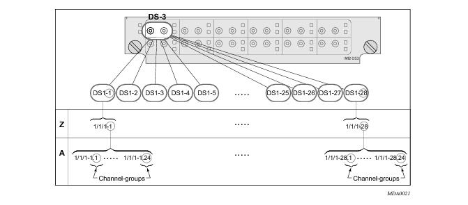
The MDAs displayed in the MDA Provisioned column in the following output are a 12-port channelized DS3 MDA (m12-ds3) on card 1, MDA slot 1, and a 1-port channelized OC12-SFP MDA (m1-choc12-sfp) on card 1, MDA slot 2.
 
A:ALA-A# show mda 1
===============================================================================
MDA 1/1
===============================================================================
Slot  Mda   Provisioned           Equipped              Admin     Operational  
            Mda-type              Mda-type              State     State        
-------------------------------------------------------------------------------
1     1     m12-ds3               m12-ds3               up        provisioned  
===============================================================================
ALA-A# show mda 2
===============================================================================
MDA 1/2
===============================================================================
Slot  Mda   Provisioned           Equipped              Admin     Operational  
            Mda-type              Mda-type              State     State        
-------------------------------------------------------------------------------
1     2     m1-choc12-sfp         m1-choc12-sfp         up        provisioned  
===============================================================================
A:ALA-A#
 
Configuring a Channelized DS3 Port
Figure 12 depicts the logic of the DS3 port configuration.
Figure 12: Channelized DS3 Port Structure
The following describes steps to configure a channelized port on a 12-port DS3 MDA:
A:ALA-A>config# port 7/1/1
A:ALA-A>config>port# tdm
In order to set the channelized mode on a port, the DS3 parameter must be in a shut down state. Clear channel uses out-of-band signaling, not in-band signaling, so the channel's entire bit rate is available. Channelized ports use in-band signalling and must be explicitly enabled.
A:ALA-A>config>port>tdm# ds3
A:ALA-A>config>port>tdm>ds3# shutdown
A:ALA-A>config>port>tdm>ds3# channelized ds1
DS3 frame relay
A:ALA-A>config>port>tdm>ds3# no shutdown
A:ALA-A>config>port>tdm>ds3# exit
In the DS1 context, configure DS0 channel groups parameters. 24 timeslots can be configured per channel group.
A:ALA-A>config>port>tdm# ds1 1
A:ALA-A>config>port>tdm>ds1# no shutdown
A:ALA-A>config>port>tdm>ds1# channel-group 1
A:ALA-A>config>port>tdm>ds1>channel-group# timeslots 1
A:ALA-A>config>port>tdm>ds1>channel-group# encap-type frame-relay 
DS1 frame-relay
A:ALA-A>config>port>tdm>ds1>channel-group# no shutdown
A:ALA-A>config>port>tdm>ds1>channel-group# exit
A:ALA-A>config>port>tdm>ds1# channel-group 2
A:ALA-A>config>port>tdm>ds1>channel-group# timeslots 2-10
A:ALA-A>config>port>tdm>ds1>channel-group# no shutdown
A:ALA-A>config>port>tdm>ds1>channel-group# exit
A:ALA-A>config>port>tdm>ds1# exit
A:ALA-A>config>port>tdm# ds1 2
A:ALA-A>config>port>tdm>ds1# channel-group 1
A:ALA-A>config>port>tdm>ds1>channel-group# timeslots 1
A:ALA-A>config>port>tdm>ds1>channel-group# exit
A:ALA-A>config>port>tdm>ds1# no shutdown
A:ALA-A>config>port>tdm>ds1# channel-group 2
A:ALA-A>config>port>tdm>ds1>channel-group# timeslots 2
A:ALA-A>config>port>tdm>ds1>channel-group# exit
A:ALA-A>config>port>tdm>ds1# no shutdown
 
The following output displays the channelized mode configuration:
A:ALA-A>config>port># info
----------------------------------------------
        tdm
            ds3 ds3
                channelized ds1
                no shutdown
            exit
            ds1 ds1-1
                channel-group 1
                    encap-type frame-relay
                    timeslots 1
                    frame-relay
                    exit
                    no shutdown
                exit
                channel-group 2
                    shutdown
                    timeslots 2-10
                exit
                no shutdown
            exit
            ds1 ds1-2
                channel-group 1
                    shutdown
                    timeslots 1
                exit
                channel-group 2
                    timeslots 2
                    no shutdown
                exit
                no shutdown
            exit
        exit
        no shutdown
----------------------------------------------
A:ALA-A>config>port#
 
Services can be applied to the configured channelized ports. The following example shows the CLI usage to configure a customer IES service with interface SAPs on the channelized ports. Refer to the 7750 SR Services Guide for information to configure services.
A:ALA-A>config>service# ies 103 customer 1 create
A:ALA-A>config>service>ies$ interface test1 create
A:ALA-A>config>service>ies>if$ address 102.21.1.1/24
A:ALA-A>config>service>ies>if# sap 7/1/1.1.2 create
A:ALA-A>config>service>ies>if>sap$ exit
A:ALA-A>config>service>ies>if# no shutdown
A:ALA-A>config>service>ies>if# exit
A:ALA-A>config>service>ies# interface test2 create
A:ALA-A>config>service>ies>if$ address 102.22.1.1/24
A:ALA-A>config>service>ies>if$ sap 7/1/1.2.1 create
A:ALA-A>config>service>ies>if>sap$ exit
A:ALA-A>config>service>ies>if# no shutdown
A:ALA-A>config>service>ies>if# exit
A:ALA-A>config>service>ies>if# 
 
 
The following output displays the channelized ports (7/1/1.1.1 and 7/1/1.1.2) applied to SAPs on the IES service configuration.
A:ALA-A>config>service>ies# info
----------------------------------------------
...
        ies 103 customer 1 vpn 103 create
            interface "test2" create
                address 102.22.1.1/24
                sap 7/1/1.2.1 create
                exit
            exit
            interface "test1" create
                address 102.21.1.1/24
                sap 7/1/1.1.2 create
                exit
            exit
            no shutdown
        exit
...
----------------------------------------------
A:ALA-A>config>service>ies#
 
Configuring a Channelized OC-12-SFP Port
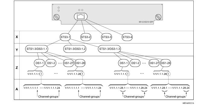
Figure 13 depicts the logic of the channelized OC-12 port configuration.
Figure 13: Channelized OC-12 Port Structure
The following describes an example to configure a channelized port on a 1-port channelized OC-12-SFP MDA:
ALA-A>config# port 5/2/1
At this level you must choose the tributary. When provisioning DS3 nodes on a channelized OC-12 MDA, you must provision the parent STS1-1 SONET path first.
A:ALA-A>config>port# sonet-sdh
A:ALA-A>config>port>sonet-sdh# path sts1-1.1
A:ALA-A>config>port>sonet-sdh>path# no shutdown
A:ALA-A>config>port>sonet-sdh>path# exit
The following displays the output:
A:ALA-A>config>port>sonet-sdh# info
----------------------------------------------
        sonet-sdh
            path sts1-1.1
                no shutdown
            exit
        exit
----------------------------------------------
A:ALA-A>config>port>sonet-sdh#
In order to set the channelized mode on a port, the DS3 parameter must be in a shut down state. Clear channel uses out-of-band signaling, not in-band signaling, so the channel's entire bit rate is available. Channelized ports use in-band signalling and must be explicitly enabled.
A:ALA-A>config>port# tdm
A:ALA-A>config>port>tdm# ds3 1.1
A:ALA-A>config>port>tdm>ds3# shutdown
A:ALA-A>config>port>tdm>ds3# channelized ds1
A:ALA-A>config>port>tdm>ds3# no shutdown
A:ALA-A>config>port>tdm>ds3# exit
The following displays the output:
A:ALA-A>config>port# info
----------------------------------------------
        sonet-sdh
            path sts12
                no shutdown
            exit
            path sts3-1
                no shutdown
            exit
            path sts1-1.1
                no shutdown
            exit
        exit
        tdm
            ds3 ds3-1.1
                channelized
                no shutdown
            exit
        exit
        no shutdown
----------------------------------------------
A:ALA-A>config>port#
 
In the TDM context, configure DS0 channel groups parameters. 24 timeslots can be configured per channel group.
A:ALA-A>config>port>tdm# ds1 1.1.1
A:ALA-A>config>port>tdm>ds1# no shutdown
A:ALA-A>config>port>tdm>ds1# channel-group 1
A:ALA-A>config>port>tdm>ds1>channel-group# timeslots 1
A:ALA-A>config>port>tdm>ds1>channel-group# no shutdown
A:ALA-A>config>port>tdm>ds1>channel-group# exit
A:ALA-A>config>port>tdm>ds1# no shutdown
A:ALA-A>config>port>tdm>ds1# channel-group 2
A:ALA-A>config>port>tdm>tds1>channel-group# timeslots 2
A:ALA-A>config>port>tdm>ds1>channel-group# no shutdown
A:ALA-A>config>port>tdm>ds1>channel-group# exit
A:ALA-A>config>port>tdm>ds1# exit
 
 
A:ALA-A>config>port>tdm# info
----------------------------------------------
        sonet-sdh
            path sts12
                no shutdown
            exit
            path sts3-1
                no shutdown
            exit
            path sts1-1.1
                no shutdown
            exit
        exit
        tdm
            ds3 ds3-1.1
                channelized
                no shutdown
            exit
            ds1 ds1-1.1.1
                channel-group 1        (see SAP 5/2/1.1.1.1.1 below)
                    timeslots 1
                    no shutdown
                exit
                channel-group 2        (see SAP 5/2/1.1.1.1.2 below)
                    timeslots 2
                    no shutdown
                exit
                no shutdown
            exit
        exit
        no shutdown
----------------------------------------------
A:ALA-A>config>port>tdm#
 
Services can be applied to the configured channelized ports. The following example shows the CLI usage to configure a customer IES service with interface SAPs on the channelized ports. Refer to the 7750 SR Services Guide for detailed information to configure services.
A:ALA-A>config>service# ies 104 customer 1 create
A:ALA-A>config>service>ies$ interface testA create
A:ALA-A>config>service>ies>if$ address 192.22.1.1/24
A:ALA-A>config>service>ies>if# sap 5/2/1.1.1.1.1 create
A:ALA-A>config>service>ies>if>sap$ exit
A:ALA-A>config>service>ies>if# no shutdown
A:ALA-A>config>service>ies>if# exit
A:ALA-A>config>service>ies# interface testB create
A:ALA-A>config>service>ies>if$ address 192.23.1.1/24
A:ALA-A>config>service>ies>if# sap 5/2/1.1.1.1.2 create
A:ALA-A>config>service>ies>if>sap$ exit
A:ALA-A>config>service>ies>if# no shutdown
A:ALA-A>config>service>ies>if# exit
A:ALA-A>config>service>ies# no shutdown
 
 
The following output displays the channelized ports 5/2/1.1.1.1.1 and 5/2/1.1.1.1.2) applied to SAPs on the IES service configuration.
A:ALA-A>config>service>ies# info
----------------------------------------------
            interface "testA" create
                address 192.22.1.1/24
                sap 5/2/1.1.1.1.1 create
                exit
            exit
            interface "testB" create
                address 192.23.1.1/24
                sap 5/2/1.1.1.1.2 create
                exit
            exit
            no shutdown
----------------------------------------------
A:ALA-A>config>service>ies#
 
 
Configuring a Channelized Any Service Any Port (ASAP) OC3-SFP Port
This section provides examples to configure PPP, FR, cHDLC, and ATM n*DS0 channels on a channelized port on channelized ASAP OC-3 SFP MDA in slot 1/1/1. The ASAP OC-12 SFP MDA also supports the SONET options.
ALA-A>config# port 1/1/1
At this level you must choose the tributary. When provisioning DS3 nodes on a channelized ASAP OC-3 MDA, you must provision the parent STS1-1 SONET path first.
 
A:ALA-A>config>port# sonet-sdh
A:ALA-A>config>port>sonet-sdh# framing sdh
A:ALA-A>config>port>sonet-sdh# path sts1-1
A:ALA-A>config>port>sonet-sdh>path# no shutdown
A:ALA-A>config>port>sonet-sdh>path# exit
A:ALA-A>config>port>sonet-sdh# info
----------------------------------------------
        sonet-sdh
               framing sdh
               path sts1-1
                    no shutdown
               exit
        exit
----------------------------------------------
A:ALA-A>config>port>sonet-sdh#
In order to set the channelized mode on a port, the DS3 parameter must be in a shut down state. Clear channel uses out-of-band signaling, not in-band signaling, so the channel's entire bit rate is available. Channelized ports use in-band signalling and must be explicitly enabled.
 
A:ALA-A>config>port# tdm
A:ALA-A>config>port>tdm# ds3 1
A:ALA-A>config>port>tdm>ds3# shutdown
A:ALA-A>config>port>tdm>ds3# channelized e1
A:ALA-A>config>port>tdm>ds3# no shutdown
A:ALA-A>config>port>tdm>ds3# exit
A:ALA-A>config>port# info
----------------------------------------------
        sonet-sdh
               path sts1-1
                    no shutdown
               exit
        exit
        tdm
           ds3 1
                channelized e1
                no shutdown 
            exit
        exit
        no shutdown
----------------------------------------------
A:ALA-A>config>port#
In the TDM E1 context, configure DS0 channel groups and their parameters. For a DS1 channel-group, up to 24 timeslots can be assigned (numbered 1— 24). For an E1 channel-group, up to 31 timeslots can be assigned (numbered 2 — 32). For ATM, all timeslots are auto-configured when a channel group gets created (there is no sub-E1 for ATM). ATM, Frame Relay and BCP-NULL encapsulation examples follow:
A:ALA-A>config>port>tdm# e1 1.1
A:ALA-A>config>port>tdm>e1# channel-group 1
A:ALA-A>config>port>tdm>e1>channel-group# timeslots 2
A:ALA-A>config>port>tdm>e1>channel-group# no shutdown
A:ALA-A>config>port>tdm>e1>channel-group# 
A:ALA-A>config>port>tdm>e1# no shutdown
A:ALA-A>config>port>tdm>e1# channel-group 2
A:ALA-A>config>port>tdm>e1>channel-group# timeslots 3
A:ALA-A>config>port>tdm>e1>channel-group# encap-type frame-relay
A:ALA-A>config>port>tdm>e1>channel-group# no shutdown
A:ALA-A>config>port>tdm>e1>channel-group# exit
A:ALA-A>config>port>tdm>e1# channel-group 3
A:ALA-A>config>port>tdm>e1>channel-group# timeslots 11,12
A:ALA-A>config>port>tdm>e1>channel-group# encap-type cisco-hdlc
A:ALA-A>config>port>tdm>e1>channel-group# no shutdown
A:ALA-A>config>port>tdm>e1>channel-group# exit
A:ALA-A>config>port>tdm>e1# no shutdown
A:ALA-A>config>port>tdm>e1# exit
A:ALA-A>config>port>tdm# e1 1.2
A:ALA-A>config>port>tdm>e1# no shutdown
A:ALA-A>config>port>tdm>e1# channel-group 1
A:ALA-A>config>port>tdm>e1>channel-group# encap-type atm
A:ALA-A>config>port>tdm>e1>channel-group# no shutdown
A:ALA-A>config>port>tdm>e1>channel-group# exit
A:ALA-A>config>port>tdm>e1# no shutdown
A:ALA-A>config>port>tdm# info
----------------------------------------------
        tdm
           ds3 1
                channelized e1
                no shutdown
            exit
           e1 1.1
                channel-group 1
                     timeslots 2
                     no shutdown
               exit
                channel-group 2
                    encap-type frame-relay
                    frame-relay
                    exit
                    timeslots 10
                    no shutdown
                exit
                channel-group 3
                    encap-type cisco-hdlc
                    cisco-hdlc
                    exit
                    timeslots 11,12
                    no shutdown
                exit
                no shutdown 
            exit
           e1 1.2
                channel-group 1
                    encap-type atm
                    atm
                    exit
                    no shutdown
                exit
                no shutdown 
        exit
        no shutdown
----------------------------------------------
A:ALA-A>config>port>tdm#
Services can now be applied to the configured channelized ports. Follow examples of other channelized ports in this document.
 
Configuring Cisco HDLC on a Channelized Port
Use the following CLI syntax to configure cHDLC:
sonet cHDLC
CLI Syntax: config# port port-id
tdm
ds3 [sonet-sdh-index]
channelized {ds1|e1}
no shutdown
ds1
channel-group channel-group
cisco-hdlc
down-count down-count
keepalive time-interval
up-count up-count
encap-type {bcp-null|bcp-dot1q|ipcp|ppp-auto|frame-relay|wan-mirror|cisco-hdlc}
timeslots timeslots
no shutdown
 
The following example displays SONET/SDH access mode configuration command usage:
Example: A:ALA-29>config>port>tdm# ds3
A:ALA-29>config>port>tdm>ds3# channelized ds1
A:ALA-29>config>port>tdm>ds3# no shutdown
A:ALA-29>config>port>tdm>ds3# exit
A:ALA-29>config>port>tdm# ds1 1
A:ALA-29>config>port>tdm>ds1# no shutdown
A:ALA-29>config>port>tdm>ds1# channel-group 1
A:ALA-29>config>port>tdm>ds1>channel-group# timeslots 1-20
A:ALA-29>config>port>tdm>ds1>channel-group# encap-type cisco-hdlc
A:ALA-29>config>port>tdm>ds1>channel-group# exit
A:ALA-29>config>port>tdm>ds1# channel-group 1
A:ALA-29>config>port>tdm>ds1>channel-group# no shutdown
A:ALA-29>config>port>tdm>ds1>channel-group# exit
A:ALA-29>config>port>tdm>ds1# exit
A:ALA-29>config>port>tdm#
 
The following example displays a configuration:
A:ALA-29>config>port# inf
----------------------------------------------
        tdm
            ds3
                channelized ds1
                no shutdown
            exit
            ds1 1
                channel-group 1
                    encap-type cisco-hdlc
                    timeslots 1-20
                    cisco-hdlc
                    exit
                    no shutdown
                exit
                no shutdown
            exit
        exit
        no shutdown
----------------------------------------------
A:ALA-29>config>port#
 
Configuring Channelized STM1/OC3 Parameters
The following example displays basic syntax to configure channelized STM1/OC3 parameters:
CLI Syntax: config# port port-id
sonet-sdh
framing {sonet|sdh}
group sonet-sdh-index payload {tu3|vt2|vt15}
path [sonet-sdh-index]
payload {sts3|tug3|ds3|e3}
trace-string [trace-string]
no shutdown
 
Example: config# port 5/2/1
config>port# sonet-sdh
config>port>sonet-sdh# framing sdh
config>port>sonet-sdh# path sts3
config>port>sonet-sdh>path# trace-string "HO-path"
config>port>sonet-sdh>path# exit
config>port>sonet-sdh# group tug3-1 payload vt2
config>port>sonet-sdh# group tug3-3 payload vt2
config>port>sonet-sdh# path vt2-1.1.1
config>port>sonet-sdh>path# trace-string "LO-path 3.7.3"
config>port>sonet-sdh>path# no shutdown
config>port>sonet-sdh>path# exit
config>port>sonet-sdh# exit
config>port# tdm
config>port>tdm# e1 1.1.1
config>port>tdm>e1# channel-group 1
config>port>tdm>e1>channel-group# timeslots 2-32
config>port>tdm>e1>channel-group# no shutdown
config>port>tdm>e1>channel-group# exit
config>port>tdm>e1# exit
config>port>tdm# e1 3.7.3
config>port>tdm>e1# channel-group 2
config>port>tdm>e1>channel-group# timeslots 2-32
config>port>tdm>e1>channel-group# no shutdown
config>port>tdm>e1>channel-group# exit
 
The following displays the configuration output:
A:ALA-49>config>port# info
----------------------------------------------------------------------------------------
        sonet-sdh
            framing sdh
            path sts3
                trace-string "HO-path"
                no shutdown
            exit
            group tug3-1 payload vt2
            group tug3-3 payload vt2
            path vt2-1.1.1
                trace-string "LO-path 3.7.3"
                no shutdown
            exit
            path vt2-3.7.3
                no shutdown
            exit
        exit
        tdm
            e1 1.1.1
                channel-group 1
                    timeslots 2-32
                    no shutdown
                exit
                no shutdown
            exit
            e1 3.7.3
                channel-group 2
                    timeslots 2-32
                    no shutdown
                exit
                no shutdown
            exit
        exit
        no shutdown
----------------------------------------------
A:ALA-49>config>port#
 
 
Configuring Cpipe Port Parameters
Before a Cpipe service can be provisioned, the following entities must be configured.
 
Configuring a DS1 Port
The following displays an example of a DS1 port configured for CES.
A:sim216#  show port 1/5/1.1.3.1 
===============================================================================
TDM DS1 Interface
===============================================================================
Description        : DS1
Interface          : 1/5/1.1.3,1 
Type               : ds1                     Framing              : esf       
Admin Status       : up                      Oper Status          : up        
Physical Link      : yes                     Clock Source         : loop-timed
Signal Mode        : none                                                     
Last State Change  : 10/31/2006 14:23:12     Channel IfIndex      : 580943939 
Loopback           : none                    Invert Data          : false     
Remote Loop respond: false                   In Remote Loop       : false     
Load-balance-algo  : default                 Egr. Sched. Pol      : n/a       
BERT Duration      : N/A                     BERT Pattern         : none      
BERT Synched       : 00h00m00s               Err Insertion Rate   : 0         
BERT Errors        : 0                       BERT Status          : idle      
BERT Total Bits    : 0                                                        
Cfg Alarm          : ais los                                                  
Alarm Status       :                                                          
===============================================================================
A:sim216# 
 
Configuring a Channel Group
The following displays an example of a DS1 channel group configured for CES.
A:sim216#  show port 1/5/1.1.3.1  
===============================================================================
TDM DS0 Chan Group
===============================================================================
Description        : DS0GRP
Interface          : 1/5/1.1.3.1                                              
TimeSlots          : 1-12                                                      
Speed              : 64                      CRC                  : 16         
Admin Status       : up                      Oper Status          : up         
Last State Change  : 10/31/2006 14:23:12     Chan-Grp IfIndex     : 580943940  
Configured mode    : access                  Encap Type           : cem        
Admin MTU          : 4112                    Oper MTU             : 4112       
Physical Link      : Yes                     Bundle Number        : none       
Idle Cycle Flags   : flags                   Load-balance-algo    : default    
Egr. Sched. Pol    : n/a                                                       
===============================================================================
A:sim216# 
 
Configuring ATM SAPs
 
ATM SAP in an IES Service
The following displays an IES service SAP configuration:
:ALA-701>config>service>ies# info
----------------------------------------------
            interface "atm_1" create
                address 2.3.4.1/24
                sap 2/1/1:17/24 create
                exit
            exit
            interface "atm_2" create
                address 2.4.5.1/24
                sap 2/1/1:18/300 create
                exit
            exit
            no shutdown
----------------------------------------------
B:ALA-701>config>service>ies#
 
ATM SAP in an Epipe Service
The following displays an Epipe service SAP configuration:
B:ALA-701>config>service# info
----------------------------------------------
...
            epipe 5 customer 1 create
                shutdown
                sap 2/1/2:15/25 create
                exit
                sap 2/1/3:25/35 create
                exit
            exit
----------------------------------------------
B:ALA-701>config>service#
Configuring DWDM Port Parameters
The following example displays a DWDM port configuration:
*A:ALA-A>config>port>dwdm># info
----------------------------------------------
           channel 44
           wavetracker
               power-control
                   target-power -7.50
               exit
               encode key1 205 key2 749
           exit
----------------------------------------------
 
*A:ALA-A>config>port>dwdm># info detail
----------------------------------------------
           channel 44
           wavetracker
               power-control
                   target-power -7.50
               exit
               encode key1 205 key2 749
               report-alarm enc-fail enc-degr pwr-fail pwr-degr pwr-high pwr-low
           exit
           rxdtv-adjust
----------------------------------------------
*A:ALA-A>config>port>dwdm># wavetracker
 
*A:ALA-A>config>port>dwdm>wavetracker># info
----------------------------------------------
               power-control
                   target-power -7.50
               exit
               encode key1 205 key2 749
----------------------------------------------
 
 
*A:ALA-A>config>port>dwdm>wavetracker># info detail
----------------------------------------------
               power-control
                   target-power -7.50
               exit
               encode key1 205 key2 749
               report-alarm enc-fail enc-degr pwr-fail pwr-degr pwr-high pwr-low
----------------------------------------------
*A:ALA-A>config>port>dwdm># info detail
----------------------------------------------
channel 44
wavetracker
power-control
target-power -7.50
exit
encode key1 205 key2 749
report-alarm enc-fail enc-degr pwr-fail pwr-degr pwr-high pwr-low
exit
tdcm
channel 0
mode automatic
dispersion 0
sweep start -1200 end 1200
report-alarm nrdy mth mtl unlck tlim einv com
exit
amplifier
report-alarm ild tmp mth mtl los lop com
exit
rxdtv-adjust
----------------------------------------------
Configuring WaveTracker Parameters
 
The following example displays the default configuration with WaveTracker disabled:
*A:ALA-A>config>port>dwdm># info
----------------------------------------------
           channel 44
----------------------------------------------
 
 
*A:ALA-A>config>port>dwdm># info detail
----------------------------------------------
           channel 44
           wavetracker
               no power-control
               no encode
               report-alarm enc-fail enc-degr pwr-fail pwr-degr pwr-high pwr-low
           exit
           rxdtv-adjust
----------------------------------------------
The following example displays a configuration with DWDM channel 44, WaveTracker power control transmit power at -7.5 dBm and WaveTracker encoded keys 205 and 749
*A:ALA-A>config>port>dwdm># info
----------------------------------------------
           channel 44
           wavetracker
               power-control
                   target-power -7.50
               exit
               encode key1 205 key2 749
           exit
----------------------------------------------
 
*A:ALA-A>config>port>dwdm># info detail
----------------------------------------------
           channel 44
           wavetracker
               power-control
                   target-power -7.50
               exit
               encode key1 205 key2 749
               report-alarm enc-fail enc-degr pwr-fail pwr-degr pwr-high pwr-low
           exit
           rxdtv-adjust
----------------------------------------------
*A:ALA-A>config>port>dwdm># wavetracker
 
*A:ALA-A>config>port>dwdm>wavetracker># info
----------------------------------------------
               power-control
                   target-power -7.50
               exit
               encode key1 205 key2 749
----------------------------------------------
 
 
*A:ALA-A>config>port>dwdm>wavetracker># info detail
----------------------------------------------
               power-control
                   target-power -7.50
               exit
               encode key1 205 key2 749
               report-alarm enc-fail enc-degr pwr-fail pwr-degr pwr-high pwr-low
----------------------------------------------
Following is an example of the show port <portId> wavetracker command for the non-default WaveTracker configuration above:
*A:ALA-A# show port 3/2/1 wavetracker
 
===============================================================================
Wavelength Tracker
===============================================================================
Power Control      : Enabled                  WaveKey Status     : Enabled
Target Power       :  -7.50 dBm               WaveKey 1          : 205
Measured Power     :  -7.49 dBm               WaveKey 2          : 749
 
Cfg Alarms         : enc-fail enc-degr pwr-fail pwr-degr pwr-high pwr-low
Alarm Status       :
 
Maximum Power      :   0.47 dBm               Power Upper Margin :   7.96 dB
Minimum Power      : -21.23 dBm               Power Lower Margin :  13.74 dB
===============================================================================
Following are the Wavetracker keys allowed for each DWDM channel:
ITU      Key1  Key1  Key2  Key2
Channel  Min   Max   Min   Max
-------  ----  ----  ----  ----
61       1548  1548  2032  2032
59       1     15    545   559 
58       18    32    562   576 
57       35    49    579   593 
56       52    66    596   610 
54       69    83    613   627 
53       86    100   630   644 
52       103   117   647   661 
51       120   134   664   678 
49       137   151   681   698 
48       154   168   698   712 
47       171   185   715   729 
46       188   202   732   746 
44       205   219   749   763 
43       222   236   766   780 
42       239   253   783   797 
41       256   270   800   814 
39       273   287   817   831 
38       290   304   834   848 
37       307   321   851   865 
36       324   338   868   882 
34       341   355   885   899 
33       358   372   902   916 
32       375   389   919   933 
31       392   406   936   950 
29       409   423   953   967 
28       426   440   970   984 
27       443   457   987   1001
26       460   474   1004  1018
24       477   491   1021  1035
23       494   508   1038  1052
22       511   525   1055  1069
21       528   542   1072  1086
60       1089  1103  1573  1587
55       1106  1120  1590  1604
50       1123  1137  1607  1621
45       1140  1154  1624  1638
40       1157  1171  1641  1655
35       1174  1188  1658  1672
30       1191  1205  1675  1689
25       1208  1222  1692  1706
20       1225  1239  1709  1723
19       1242  1256  1726  1740
18       1259  1273  1743  1757
17       1276  1290  1760  1774
595      1293  1307  1777  1791
585      1310  1324  1794  1808
575      1327  1341  1811  1825
565      1344  1358  1828  1842
545      1361  1375  1845  1859
535      1378  1392  1862  1876
525      1395  1409  1879  1893
515      1412  1426  1896 	1910
495      1429  1443  1913  1927
485      1446  1460  1930  1944
475      1463  1477  1947  1961
465      1480  1494  1964  1978
445      1497  1511  1981  1995
435      1514  1528  1998  2012
425      1531  1545  2015  2029
415      1548  1562  2032  2046
395      3585  3599  2049  2063
385      3602  3616  2066  2080
375      3619  3633  2083  2097
365      3636  3650  2100  2114
345      3653  3667  2117  2131
335      3670  3684  2134  2148
325      3687  3701  2151  2165
315      3704  3718  2168  2182
295      3721  3735  2185  2199
285      3738  3752  2202  2216
275      3755  3769  2219  2233
265      3772  3786  2236  2250
245      3789  3803  2253  2267
235      3806  3820  2270  2284
225      3823  3837  2287  2301
215      3840  3854  2304  2318
605      3857  3871  2321  2335
555      3874  3888  2338  2352
505      3891  3905  2355  2369
455      3908  3922  2372  2386
405      3434  3448  3946  3960
355      3451  3465  3963  3977
305      3468  3482  3980  3994
255      3485  3499  3997  4011
205      3502  3516  4014  4028
195      3519  3533  4031  4045
185      3536  3550  4048  4062
175      3553  3567  4065  4079
 
Configuring OTU Port Parameters
The following example displays an OTU port configuration:
*A:ALA-A>config>port>otu# info detail
----------------------------------------------
           otu2-lan-data-rate 11.049
           sf-sd-method fec
           sf-threshold 5
           sd-threshold 7
           fec enhanced
           no report-alarm otu-ais otu-ber-sd otu-tim otu-iae otu-biae fec-sd
           no report-alarm fec-fail fec-uncorr odu-ais odu-oci odu-lck odu-bdi
           no report-alarm odu-tim opu-tim opu-plm
           report-alarm loc los lof lom otu-ber-sf otu-bdi fec-sf
           sm-tti
               tx auto-generated
               expected auto-generated
               no mismatch-reaction
           exit
           pm-tti
               tx auto-generated
               expected auto-generated
               no mismatch-reaction
           exit
           psi-tti
               tx auto-generated
               expected auto-generated
               no mismatch-reaction
           exit
           psi-payload
               tx auto
               expected auto
               no mismatch-reaction
           exit
----------------------------------------------
The following example displays the show port <portId> otu detail for the default OTU configuration above:
*A:ALA-A# show port 3/2/1 otu detail
 
===============================================================================
OTU Interface
===============================================================================
OTU Status         : Enabled                    FEC Mode         : enhanced
Async Mapping      : Disabled                   Data Rate        : 11.049 Gb/s
 
Cfg Alarms         : loc los lof lom otu-ber-sf otu-bdi fec-sf
Alarm Status       :
SF/SD Method       : FEC                        SF Threshold     : 1E-5
                                                SD Threshold     : 1E-7
 
SM-TTI Tx (auto)   : ALA-A:3/2/1/C44
SM-TTI Ex (bytes)  : (Not Specified)
SM-TTI Rx          : ALA-A:5/2/1/C34
OTU-TIM reaction   : none
 
PM-TTI Tx (auto)   : ALA-A:3/2/1/C44
PM-TTI Ex (bytes)  : (Not Specified)
PM-TTI Rx          : ALA-A:5/2/1/C34
ODU-TIM reaction   : none
 
PSI-TTI Tx (auto)  : ALA-A:3/2/1/C44
PSI-TTI Ex (bytes) : (Not Specified)
PSI-TTI Rx         : ALA-A:5/2/1/C34
OPU-TIM reaction   : none
 
PSI-PT Tx (auto)   : 0x03 (syncCbr)
PSI-PT Ex (auto)   : 0x03 (syncCbr)
PSI-PT Rx          : 0x03 (syncCbr)
OPU-PLM reaction   : none
===============================================================================
OTU Statistics
===============================================================================
Elapsed Seconds                                                10
-------------------------------------------------------------------------------
Near End Statistics                                     Count
-------------------------------------------------------------------------------
FEC Corrected 0s                                                0
FEC Corrected 1s                                                0
FEC Unrrectable Sub-rows                                        0
FEC ES                                                          0
FEC SES                                                         0
FEC UAS                                                         0
Pre-FEC BER                                             0.000E+00
Post-FEC BER                                            0.000E+00
-------------------------------------------------------------------------------
SM BIP8                                                         0
SM ES                                                           0
SM SES                                                          0
SM UAS                                                          0
SM-BIP8-BER                                             0.000E+00
-------------------------------------------------------------------------------
PM BIP8                                                         0
PM ES                                                           0
PM SES                                                          0
PM UAS                                                          0
PM-BIP8-BER                                             0.000E+00
-------------------------------------------------------------------------------
NPJ                                                             0
PPJ                                                             0
 
-------------------------------------------------------------------------------
Far End Statistics                                      Count
-------------------------------------------------------------------------------
SM BEI                                                          0
PM BEI                                                          0
===============================================================================
 
The window over which the Bit Error Rate (BER) determined is based on the configured threshold level. The higher the error rate the shorter the window and as the error rate decreases the window increases.
 
 
Configuring ATM Interface Parameters
ATM interface parameters can only be configured for SONET/SDH ports/paths and TDM ports/channels supporting ATM encapsulation, and for IMA multilink bundles.
ATM interface parameters allow users to configure characteristics of an ATM interface. The 7750 SR product family supports configuration of the following ATM interface characteristics:
 
PLCP/Direct Mapping
Setting mapping to PLCP changes the effective speed of a DS3 interface to 40.704 M. When a port operates in a PLCP mode, the OCD events and LCD are not applicable (including related status fields and counters).
Similarly the below-defined PLCP statuses, alarms, counters do not apply for direct mapped ports.
When a path operates in the PLCP mode, 7750 SR supports the standard ATM MIB monitoring of the PLCP operations, for example:
Table 9 illustrates how SONET alarm status, path operational status, ATM interface and PLCP status and PLCP Alarm state interact:
 
 
DS3 path configured for PLCP mapping:
 
ATM Interface Configurations
Use the following CLI syntax to configure ATM interface parameters for SONET/SDH paths:
CLI Syntax: config# port port-id
sonet-sdh
path [sonet-sdh-index]
atm
cell-format cell-format
ilmi [vpi/vci]
egress
traffic-desc traffic-desc-profile-id
ingress
traffic-desc traffic-desc-profile-id
keep-alive [poll-frequency seconds] [poll-count value] [test-frequency seconds]
protocol protocol-type
[no] shutdown
min-vp-vpi value
 
Use the following CLI syntax to configure ATM interface parameters for IMA bundles.
CLI Syntax: config>port>multilink-bundle
ima
atm
cell-format cell-format
min-vp-vpi value
 
Use the following CLI syntax to configure ATM interface parameters for TDM channels:
CLI Syntax: config# port {port-id}
tdm
ds1 [ds1-id]
channel-group 1
atm
cell-format cell-format
min-vp-vpi value
ds3 [sonet-sdh-index]
atm
cell-format cell-format
min-vp-vpi value
mapping {direct | plcp}
e1 [e1-id]
channel-group 1
atm
cell-format cell-format
min-vp-vpi value
e3 [sonet-sdh-index]
atm
cell-format cell-format
min-vp-vpi value
 
Configuring Frame Relay Parameters
Frame Relay pipes are used to provide customer-to-customer Frame Relay PVCs or to interconnect individual Frame Relay clouds.
Frame Relay parameters can only be configured in SONET/SDH and channelized TDM MDA contexts.
The following example displays a channelized interface configuration:
A:ALA-7>config>port# info detail
----------------------------------------------
        description "DS3/E3"
...
        tdm
            buildout long
            ds3 ds3
                type t3
                channelized
                clock-source loop-timed
                framing c-bit
                no feac-loop-respond
                no mdl
                no mdl-transmit
                no loopback
                report-alarm ais los
                no report-alarm oof rai looped
                no shutdown
            exit
            ds1 ds1-1
                shutdown
                framing esf
                no loopback
                report-alarm ais los
                no report-alarm oof rai looped
                channel-group 1
                    description "DS3/E3"
                    mode access
                    encap-type frame-relay
                    no mtu
                    no mac
                    timeslots 1
                    speed 64
                    crc 16
                    frame-relay
                        lmi-type itu
                        mode dte
                        n393dce 4
                        n393dte 4
                        n391dte 6
                        n392dce 3
                        n392dte 3
                        t391dte 10
                        t392dce 15
                    exit
                    no shutdown
                exit
            exit
        exit
        no shutdown
----------------------------------------------
A:ALA-7>config>port#
 
SONET/SDH Interfaces
This section applies also to FR interfaces on Sonet/SDH high-speed channels on ASAP MDAs. In order to configure Frame Relay on the associated port/channel, the frame-relay encapsulation type must be specified.
The following output displays a Frame Relay encapsulation type and the Frame Relay defaults.
A:ALA-7>config>port# info detail
----------------------------------------------
        description "OC-3/OC-12 SONET/SDH"
        access
            ingress
                pool default
                    resv-cbs default
                    slope-policy "default"
                exit
            exit
            egress
                pool default
                    resv-cbs sum
                    slope-policy "default"
                exit
            exit
        exit
        network
            egress
                pool default
                    resv-cbs default
                    slope-policy "default"
                exit
            exit
        exit
        sonet-sdh
            framing sonet
            clock-source node-timed
            no loopback
            speed oc12
            report-alarm loc lrdi lb2er-sf slof slos
            no report-alarm lais ss1f lb2er-sd lrei
            threshold ber-sd rate 6
            threshold ber-sf rate 3
            section-trace byte 0x1
            path
                description "OC-3/OC-12 SONET/SDH"
                mode access
                encap-type frame-relay
                no mtu
                no mac
                crc 32
                no scramble
                trace-string "Alcatel 7750 ALA-"
                report-alarm plop pplm puneq
                no report-alarm pais prdi prei
                signal-label 0xcf
                frame-relay
                    lmi-type itu
                    mode dte
                    n393dce 4
                    n393dte 4
                    n391dte 6
                    n392dce 3
                    n392dte 3
                    t391dte 10
                    t392dce 15
                exit
                no shutdown
            exit
        exit
        no shutdown
----------------------------------------------
A:ALA-7>config>port# pwc
 
Configuring Multilink PPP Bundles
Multilink bundles can have from 1 to 8 members (ports) specified. The bundles aggregate channelized ports which define available bandwidth to carry data over a DS1 channel. 56 multilink bundles can be configured per MDA. 256 MLPPP groups are supported per ASAP MDA. Each bundle represents a single connection between two routers.
Multilink bundling is based on a link control protocol (LCP) option negotiation that permits a system to indicate to its peer that it is capable of combining multiple physical links into a bundle.
Multilink bundling operations are modeled after a virtual PPP link-layer entity where packets received over different physical link-layer entities are identified as belonging to a separate PPP network protocol (the Multilink Protocol, or MP) and recombined and sequenced according to information present in a multilink fragmentation header. All packets received over links identified as belonging to the multilink arrangement are presented to the same network-layer protocol processing machine, whether they have multilink headers or not.
When you configure multilink bundles, consider the following guidelines:
 
A:ALA-A>config# port bundle-5/2.1
A:ALA-A>config>port# multilink-bundle
A:ALA-A>config>port>ml-bundle# member 5/2/1.ds0grp-1.1
A:ALA-A>config>port>ml-bundle# member 5/2/1.ds0grp-2.2
A:ALA-A>config>port>ml-bundle# member 5/2/1.ds0grp-1.1
 
Configuring Multilink ATM Inverse Multiplexing (IMA) Bundles
IMA bundles are supported on Channelized ASAP MDAs. The bundles aggregate E1 or DS1 ATM channels into a single logical ATM interface.
 
IMA Bundles
Use the following CLI syntax to configure IMA bundle parameters:
CLI Syntax: configure# port bundle-type-slot/mda.bundle-num
description description-string
multilink-bundle
fragment-threshold value
ima
atm
cell-format {uni|nni}
min-vp-vpi vp-vpi-value
exit
link-delay {activate |deactivate} milli-seconds
max-bandwidth number-links
version ima-version
red-differential-delay red-diff-delay down
member port-id
Configuration notes:
An IMA group has common interface characteristics (for example, configuration that applies to a logical ATM interface either configured via the IMA group context or taken from the primary link) The following list details those common IMA group interface characteristics:
Member links inherit those common characteristics from the IMA group that they are part of and as long as they are part of an IMA group. Characteristics derived from the primary link (MTU, interface mode type) can be changed on the primary link only and not on other links in the bundle or a bundle itself. The primary link is the member which has the lowest ifindex. When a member is added/deleted the primary member may be changed based on ifIndicies of all member links.
Once a path becomes part of an IMA group logical link, the path ceases to exist as a physical ATM path interface. This means that:
1.
2.
After the primary member has been added each additional member added to the group will only be accepted if it matches the configuration of the IMA group. ATM interface characteristics are not part of this verification as they are overwritten/reset to defaults when a link is added to/removed from an IMA bundle.
Upon addition to an IMA group, each added member gets automatically assigned an IMA link Id. IMA link Ids are in range from 0 to 7 and stay constant as long as the router does not reboot.
When configuring IMA bundles, consider the following guidelines:
The following example illustrates creation of an IMA bundle with 3 group members residing on a channelized OC-3 ASAP MDA in slot 5/2/1:
A:ALA-A>config# port bundle-ima-5/2.1
A:ALA-A>config>port# multilink-bundle
A:ALA-A>config>port>ml-bundle# member 5/2/1.1.1.1
A:ALA-A>config>port>ml-bundle# member 5/2/1.1.2.1
A:ALA-A>config>port>ml-bundle# member 5/2/1.1.3.1
 
Multi-Class MLPPP
The following guidelines apply to multi-class MLPPP:
MC-MLPPP and LFI (config>port>multilink-bundle>interleave-fragments) are mutually exclusive.
Prefix elision is not supported. The prefix elision (compressing common header bytes) option advises the peer that, in each of the given classes, the implementation expects to receive only packets with a certain prefix; this prefix is not to be sent as part of the information in the fragment(s) of this class.
 
IMA Test Procedure
Use the following CLI to perform IMA Test Pattern Procedure on a member link of an IMA group:
CLI Syntax: configure# port bundle-type-slot/mda.bundle-num
multilink-bundle
ima
test-pattern-procedure
test-link port-id
test-pattern [pattern]
no shutdown
An operator can deploy IMA test procedures to verify operations of IMA group and its member links. Following is a list of key points about the test pattern procedure.
1.
2.
3.
4.
5.
6.
a. Disabled: The test-link is currently not running.
b. Operating: The test pattern procedure is no shutdown and there are currently no failed-links for this running test-pattern-procedure.
c. Link-Failed: One or more links have failed the test-pattern-procedure. Execute a show port <slot/mda/port.sonet-sdh-index> ima-link command to see the failed link and received pattern value.
7.
8.
 
Configuring Bundle Protection Group Ports
Bundle Protection groups enable APS protection of one bundle residing on a working circuit of an APS group port by another bundle residing on the protection circuit of that APS group port. Bundle protection groups apply to MLPPP as well, and are configured the same way. The following examples show the process to configure BPGrp on ASAP MDAs to provide an APS protection for an IMA/MLPPP bundle.
First, two ASAP MDAs must be configured.
Example: config# card 3
config>card# mda 2
config>card>mda# mda-type m4-choc3-as-sfp
config>card>mda# no shutdown
config>card>mda# exit
config>card# exit
config# card 10
config>card# mda 2
config>card>mda# mda-type m4-choc3-as-sfp
config>card>mda# no shutdown
config>card>mda# exit
Configure an APS group with working and protection circuits on the ASAP MDAs.
Example: config# port aps-1
config>port# aps
config>port>aps# working-circuit 3/2/1
config>port>aps# protect-circuit 10/2/1
config>port>aps# exit
config>port# no shutdown
Create eight ATM DS1 channels on the APS group.
Example: config>port>aps#
config>port# sonet-sdh
config>port>sonet-sdh# path sts1-1
config>port>sonet-sdh>path# no shutdown
config>port>sonet-sdh>path# exit
config>port>sonet-sdh# exit
config>port# tdm
config>port>tdm#
config>port>tdm# ds3 1
config>port>tdm>ds3# channelized ds1
config>port>tdm>ds3# no shutdown
config>port>tdm>ds3# exit
config>port>tdm# ds1 1.1
config>port>tdm>ds1# channel-group 1
config>port>tdm>ds1>channel-group# encap-type atm
config>port>tdm>ds1>channel-group# no shutdown
config>port>tdm>ds1>channel-group# exit
config>port>tdm# ds1 1.8
config>port>tdm>ds1# channel-group 1
config>port>tdm>ds1>channel-group# encap-type atm
config>port>tdm>ds1>channel-group# no shutdown
config>port>tdm>ds1>channel-group# exit
 
Next, configure an IMA-type/MLPPP-type BPGrp with working and protection bundles on working and protection circuits of aps-1 and members the created DS1s (this creates 2 IMA bundles, one on working and one on protection circuit):
Example: config# port bpgrp-ima-1
config>port# multilink-bundle
config>port>multilink-bundle# working-bundle bundle-ima-1/1.1
config>port>multilink-bundle# protect-bundle bundle-ima-2/1.1
config>port>multilink-bundle# member aps-1.1.1.1
config>port>multilink-bundle# member aps-1.1.2.1
config>port>multilink-bundle# member aps-1.1.3.1
config>port>multilink-bundle# member aps-1.1.4.1
config>port>multilink-bundle# member aps-1.1.5.1
config>port>multilink-bundle# member aps-1.1.6.1
config>port>multilink-bundle# member aps-1.1.7.1
config>port>multilink-bundle# member aps-1.1.8.1
config>port>multilink-bundle# exit
config>port>multilink-bundle# no shutdown
config>port>multilink-bundle# exit
config>port# no shutdown
 
Finally, a service can be configured on this bundle using the BPGrp ID (for example, an ATM VC 0/32 SAP would be: sap bpg-ima-1:0/32).
Configuration Notes and Guidelines:
 
Configuring a Channelized DS1 Card
7750 SR-c12 and 7750 SR-c4 support channelized DS-1 cards. The channelization is as follows:
To make sure you have a channel-capable MDA or CMA, verify the MDA-type you are configuring by entering a show mda slot-id command.
In the following example, MDA 7 shows a channelized DS1 CMA.
A:7710-3>config# show mda
===============================================================================
MDA Summary
===============================================================================
Slot  Mda   Provisioned           Equipped              Admin     Operational  
            Mda-type              Mda-type              State     State        
-------------------------------------------------------------------------------
1     1     m60-10/100eth-tx      m60-10/100eth-tx      up        up           
      3     m4-atmoc12/3-sfp      m4-atmoc12/3-sfp      up        up           
      5     c8-10/100eth-tx       c8-10/100eth-tx       up        up           
      6     c1-1gb-sfp            c1-1gb-sfp            up        up           
      7     c8-chds1              c8-chds1              up        up           
      8     c4-ds3                c4-ds3                up        up           
===============================================================================
A:7710-3>
 
A:7710-3>config# show mda 1/7 detail
===============================================================================
MDA 1/7 detail
===============================================================================
Slot  Mda   Provisioned           Equipped              Admin     Operational  
            Mda-type              Mda-type              State     State        
-------------------------------------------------------------------------------
      7     c8-chds1              c8-chds1              up        up 
MDA Specific Data
    Maximum port count            : 8                                          
    Number of ports equipped      : 8                                          
    Network ingress queue policy  : default                                    
    Capabilities                  : TDM, PPP, FR                               
    Min channel size              : PDH DS0 Group                              
    Max channel size              : PDH DS1                                    
    Max number of channels        : 64                                         
    Channels in use               : 0                                          
 
Hardware Data
    Part number                   : Sim Part#                                  
    CLEI code                     : Sim CLEI                                   
    Serial number                 : mda-7                                      
    Manufacture date              : 01012003                                   
    Manufacturing string          : Sim MfgString mda-7                        
    Manufacturing deviations      : Sim MfgDeviation mda-7                     
    Administrative state          : up                                         
    Operational state             : up                                         
    Temperature                   : 35C                                        
    Temperature threshold         : 75C                                        
    Time of last boot             : 2006/10/02 09:28:22                        
    Current alarm state           : alarm cleared                              
    Base MAC address              : 04:7b:01:07:00:01 
===============================================================================
A:7710-3>
In the TDM E1 context, configure DS0 channel groups and their parameters. For a DS1 channel-group, up to 24 timeslots can be assigned (numbered 1..24). For an E1 channel-group, up to 31 timeslots can be assigned (numbered 2..32). For ATM, all timeslots are auto-configured when a channel group gets created (there is no sub-E1 for ATM). ATM, Frame Relay and BCP-NULL encapsulation examples follow:
ALA-A>config>port>tdm# e1 1.1
ALA-A>config>port>tdm>e1# channel-group 1
ALA-A>config>port>tdm>e1>channel-group# timeslots 2
ALA-A>config>port>tdm>e1>channel-group# no shutdown
ALA-A>config>port>tdm>e1>channel-group# 
ALA-A>config>port>tdm>e1# no shutdown
ALA-A>config>port>tdm>e1# channel-group 2
ALA-A>config>port>tdm>e1>channel-group# timeslots 3
ALA-A>config>port>tdm>e1>channel-group# encap-type frame-relay
ALA-A>config>port>tdm>e1>channel-group# no shutdown
ALA-A>config>port>tdm>e1>channel-group# exit
ALA-A>config>port>tdm>e1# channel-group 3
ALA-A>config>port>tdm>e1>channel-group# timeslots 11,12
ALA-A>config>port>tdm>e1>channel-group# encap-type cisco-hdlc
ALA-A>config>port>tdm>e1>channel-group# no shutdown
ALA-A>config>port>tdm>e1>channel-group# exit
ALA-A>config>port>tdm>e1# no shutdown
ALA-A>config>port>tdm>e1# exit
ALA-A>config>port>tdm# e1 1.2
ALA-A>config>port>tdm>e1# no shutdown
ALA-A>config>port>tdm>e1# channel-group 1
ALA-A>config>port>tdm>e1>channel-group# encap-type atm
ALA-A>config>port>tdm>e1>channel-group# no shutdown
ALA-A>config>port>tdm>e1>channel-group# exit
ALA-A>config>port>tdm>e1# no shutdown
ALA-A>config>port>tdm# info
----------------------------------------------
        tdm
           ds3 1
                no shutdown
            exit
           e1 1.1
                channel-group 1
                     timeslots 2
                     no shutdown
               exit
                channel-group 2
                    encap-type frame-relay
                    frame-relay
                    exit
                    timeslots 10
                    no shutdown
                exit
                channel-group 3
                    encap-type cisco-hdlc
                    cisco-hdlc
                    exit
                    timeslots 11,12
                    no shutdown
                exit
                no shutdown 
            exit
           e1 1.2
                channel-group 1
                    encap-type atm
                    atm
                    exit
                    no shutdown
                exit
                no shutdown 
        exit
        no shutdown
----------------------------------------------
ALA-A>config>port>tdm#
Services can now be applied to the configured channelized ports.
 
Configuring LAG Parameters
LAG configurations should include at least two ports. Other considerations include:
The following example displays LAG configuration output:
A:ALA-A>config>lag# info detail
----------------------------------------------
        description "LAG2"
        mac 04:68:ff:00:00:01
        port  1/1/1
        port  1/3/1
        port  1/5/1
        port  1/7/1
        port  1/9/1
        dynamic-cost
        port-threshold 4 action down
----------------------------------------------
A:ALA-A>config>lag#
 
Configuring BFD on LAG Links
BFD can be configured under the LAG context to create and establish the micro-BFD session per link after the LAG and associated links have been configured. An IP interface must be associated with the LAG or a VLAN within the LAG, if dot1q encapsulation is used, before the micro-BFD sessions can be established.
Complete the following steps to enable and configure BFD over the individual LAG links:
When configuring the local and remote IP address for the BFD over LAG link sessions, the local-ip parameter should always match an IP address associated with the IP interface to which this LAG is bound.  In addition, the remote-ip parameter should match an IP address on the remote system and should also be in the same subnet as the local-ip address.  If the LAG bundle is re-associated with a different IP interface, the local-ip and remote-ip parameters should be modified to match the new IP subnet.
The optional parameters that may be configured for the BFD over LAG links include:
The following is an example configuration:
*A:Dut-C>config>lag# info 
----------------------------------------------
        bfd
            family ipv4
                local-ip-address 10.120.1.2
                receive-interval 1000
                remote-ip-address 10.120.1.1
                transmit-interval 1000
                no shutdown
            exit
        exit
        no shutdown
Configuring G.8031 Protected Ethernet Tunnels
Ethernet tunnel configuration can include at most two paths. Other considerations include:
CLI Syntax: eth-tunnel 1
path 1
member 1/1/1
path 2
member 1/1/4
eth-tunnel 2
path 1
member 1/1/1
path 2
member 1/1/5
The following example displays eth-tunnel configuration output:
port 1/1/1
ethernet
encap-type dot1q
port 2/2/2
ethernet
encap-type dot1q
 
config eth-tunnel 1
path 1
member 1/1/1
control-tag 100
precedence primary
eth-cfm
mep 51 domain 1 association 1
ccm-enable
low-priority-defect allDef
mac-address 00:AE:AE:AE:AE:AE
control-mep
no shutdown
no shutdown
path 2
member 2/2/2
control-tag 200
eth-cfm
mep
mep 52 domain 1 association 2 direction down
ccm-enable
low-priority-defect allDef
mac-address 00:BE:BE:BE:BE:BE
control-mep
no shutdown
no shutdown
Service Management Tasks
This section discusses basic procedures of the following service management tasks:
 
Modifying or Deleting an MDA, MCM, or CMA
To change an MDA or CMA type already provisioned for a specific slot/card, first you must shut down the slot/MDA/port configuration and then delete the MDA, CMA, and/or the MCM from the configuration.
Note: To modify or delete CMAs, use the MDA command structure.
Use the following CLI syntax to modify an MDA:
CLI Syntax: config> port port-id
shutdown
CLI Syntax: config> card slot-number
shutdown
[no] mda mda-number
[no] mda-type mda-type
[no] hi-bw-mcast-src [alarm] [group group-id]
shutdown
Note: It is not required to shutdown and remove an MCM to remove or modify an MDA. Use the following sequence if changing the MCM type or slot configuration.
CLI Syntax: config> card slot-number
shutdown
[no] mcm mcm-number
no mcm-type mcm-type
shutdown
 
Modifying a Card Type
In order to modify the card type already provisioned for a specific slot, you must shutdown existing port configurations and shutdown and remove all MDA or CMA configurations. For 7750 SR-c12/c4 systems, after removing MDA configurations, shutdown and remove the MCM from service before modifying the card.
Note: CMAs do not require an MCM, therefore, if removing a CMA-type MDA from service, it is not required to shutdown and remove an MCM before modifying the card.
Note: You must reset the IOM after changing the MDA type from MS-ISA to any other MDA type.
Use the following CLI syntax to modify a card type already provisioned for a specific slot:
CLI Syntax: config> port port-id
[no] shutdown
CLI Syntax: config> card slot-number
mda mda-number
[no] mda-type mda-type
[no] shutdown
CLI Syntax: config> card slot-number
shutdown
[no] mcm mcm-number
no mcm-type mcm-type
shutdown
 
Deleting a Card
In order to delete the card type provisioned for a specific slot, you must shutdown existing port configurations and shutdown and remove all MDA or CMA configurations. For 7750 SR-c12/c4 systems, after removing MDA configurations, you may shutdown and remove the MCM from service before modifying the card.
Use the following CLI syntax to delete a card provisioned for a specific slot:
CLI Syntax: config> port port-id
shutdown
CLI Syntax: config> card slot-number
card-type card-type
mcm mcm-number (for 7750 SR-c12/c4 only)
no mcm-type mcm-type
no shutdown
mda mda-number
no mda-type mda-type
no shutdown
 
Deleting Port Parameters
Use the following CLI syntax to delete a port provisioned for a specific card:
CLI Syntax: config>port port-id
shutdown
no port port-id
Use the following CLI syntax to delete a port provisioned for a specific card or CMA:
CLI Syntax: config>port port-id
shutdown
 
Soft IOM Reset
This section discusses basic procedures of the following service management tasks:
 
Soft Reset
Soft reset is an advanced high availability feature that greatly reduces the impact of IOM/IMM resets either during a software upgrade or during other maintenance or debug operations. The combination of In Service Software Upgrade (ISSU) and Soft reset maximizes service availability in an operational network.
A soft reset re-initializes the control plane while the data plane continues operation with only very minimal impact to data forwarding. During the soft reset some processes that rely on the IOM control plane will not run for a duration that is similar to the duration of an IOM Hard reset. These processes include the updating of the IP forwarding table on the IOM (IP FIB downloads from the CPM), Layer 2 learning of new MAC addresses on the IOM, updating of the MAC forwarding table (for MAC addresses learned from other IOMs), ARP, Ethernet OAM 802.3ah, LLDP and handling for certain ICMP functions such as Can’t Fragment, Redirect, Host Unreachable, Network Unreachable and TTL Expired. Note that protocols and processes on the CPM continue to operate during a Soft Reset (BGP continues to learn new routes from peers, and the new routes will be downloaded to the IOM once the Soft Reset has completed).
The combination of the very small data plane impact and special soft reset enhancements for protocols ensures that most protocols do not go down and no visible impacts to most protocols are detected externally to the SR/ESS platforms. BFD timers are temporarily increased for the duration of a soft reset in order to keep BFD sessions up. Protocols such as BGP, OSPF, IS-IS, PIM, etc with default timers remain up. A protocol using aggressive timers may go down momentarily during a soft reset.
Note that although the majority of protocols stay up during a Soft Reset, there are some limitations for a few protocols. Refer to the Known Limitations section of the Release Notes for the relevant release for details.
The soft IOM reset procedure is applicable during the ISSU process and for a manual soft reset procedure.
To manually perform a soft IOM reset, enter the clear card slot-number soft command.
 
Soft Reset is supported on Ethernet IMMs and on IOMs that have Ethernet MDAs provisioned. The operator can optionally force a Soft Reset on an IOM that contains at least one MDA that supports Soft Reset but also has an MDA that does not support Soft Reset or is operationally down. To force Soft Reset in this case the hard-reset-unsupported-mdas keyword is used and the supported MDAs and the card itself are soft reset while the MDAs that do not support soft reset (or are operationally down) are hard reset.
The show card and show mda commands indicate that a soft IOM reset is occurring during the soft reset process.
Soft Reset is not supported on the following platforms: 7450 ESS-1, 7710/7750 SR-c4. On the 7710/7750 SR-c12 platforms, Soft Reset is not supported but the ISSU procedure will avoid resetting soft reset capable MDAs/CMAs.
 
Deferred MDA Reset
As part of an ISSU, soft reset is supported even if the (old) firmware version on the MDAs is not the same as the (new) firmware version in the software load to which the operator is upgrading. The soft reset is allowed to proceed by leaving the previous version of the firmware running while upgrading the rest of the MDA/IOM/IMM. The operator can then issue a hard reset of the MDA/IMM at some time in the future to upgrade the firmware.
The soft reset is only allowed to proceed if the older firmware is compatible with the new IOM/IMM software load. Otherwise the soft reset is blocked and a hard reset must be used instead.
After a soft reset has completed, a log event will be raised if necessary to warn the operator that the MDA (or IMM) is running older firmware and that they can perform a hard reset of the MDA (or IMM) at some point if desired.
If the MDA/IMM is never hard reset by the operator, and then in the future another s/w upgrade is performed, and the older firmware is no longer compatible with the newest load being upgraded to, then the soft reset will be blocked (or an automatic hard reset will occur for Major ISSU).
Note: The operator can see if they are running with older MDA/IMM firmware at any time by using the show mda detail command.