For feedback and comments:
documentation.feedback@alcatel-lucent.com

Table of Contents Previous Next PDF


OSPF
In This Chapter
This chapter provides information about configuring the Open Shortest Path First (OSPF) protocol.
Topics in this chapter include:
Configuring OSPF
OSPF (Open Shortest Path First) is a hierarchical link state protocol. OSPF is an interior gateway protocol (IGP) used within large autonomous systems (ASs). OSPF routers exchange state, cost, and other relevant interface information with neighbors. The information exchange enables all participating routers to establish a network topology map. Each router applies the Dijkstra algorithm to calculate the shortest path to each destination in the network. The resulting OSPF forwarding table is submitted to the routing table manager to calculate the routing table.
When a router is started with OSPF configured, OSPF, along with the routing-protocol data structures, is initialized and waits for indications from lower-layer protocols that its interfaces are functional. Alcatel-Lucent’s implementation of OSPF conforms to OSPF Version 2 specifications presented in RFC 2328, OSPF Version 2 and OSPF Version 3 specifications presented in RFC 2740, OSPF for IPv6. Routers running OSPF can be enabled with minimal configuration. All default and command parameters can be modified.
Changes between OSPF for IPv4 and OSPF3 for IPv6 include the following:
Key OSPF features are:
 
OSPF Areas
The hierarchical design of OSPF allows a collection of networks to be grouped into a logical area. An area’s topology is concealed from the rest of the AS which significantly reduces OSPF protocol traffic. With the proper network design and area route aggregation, the size of the route-table can be drastically reduced which results in decreased OSPF route calculation time and topological database size.
Routing in the AS takes place on two levels, depending on whether the source and destination of a packet reside in the same area (intra-area routing) or different areas (inter-area routing). In intra-area routing, the packet is routed solely on information obtained within the area; no routing information obtained from outside the area is used.
Routers that belong to more than one area are called area border routers (ABRs). An ABR maintains a separate topological database for each area it is connected to. Every router that belongs to the same area has an identical topological database for that area.
 
Backbone Area
The OSPF backbone area, area 0.0.0.0, must be contiguous and all other areas must be connected to the backbone area. The backbone distributes routing information between areas. If it is not practical to connect an area to the backbone (see area 0.0.0.5 in Figure 6) then the ABRs (such as routers Y and Z) must be connected via a virtual link. The two ABRs form a point-to-point-like adjacency across the transit area (see area 0.0.0.4).
Figure 6: Backbone Area
 
Stub Area
A stub area is a designated area that does not allow external route advertisements. Routers in a stub area do not maintain external routes. A single default route to an ABR replaces all external routes. This OSPF implementation supports the optional summary route (type-3) advertisement suppression from other areas into a stub area. This feature further reduces topological database sizes and OSPF protocol traffic, memory usage, and CPU route calculation time.
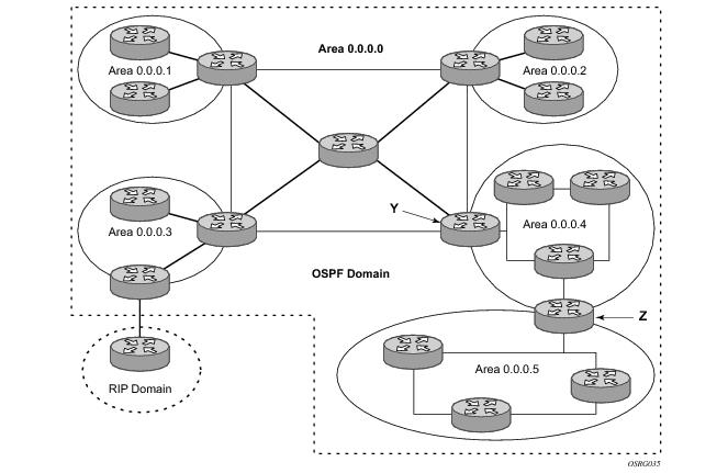
In Figure 6, areas 0.0.0.1, 0.0.0.2 and 0.0.0.5 could be configured as stub areas. A stub area cannot be designated as the transit area of a virtual link and a stub area cannot contain an AS boundary router. An AS boundary router exchanges routing information with routers in other ASs.
 
Not-So-Stubby Area
Another OSPF area type is called a Not-So-Stubby area (NSSA). NSSAs are similar to stub areas in that no external routes are imported into the area from other OSPF areas. External routes learned by OSPF routers in the NSSA area are advertised as type-7 LSAs within the NSSA area and are translated by ABRs into type-5 external route advertisements for distribution into other areas of the OSPF domain. An NSSA area cannot be designated as the transit area of a virtual link.
In Figure 6, area 0.0.0.3 could be configured as a NSSA area.
 
OSPF Super Backbone
The 77x0 PE routers have implemented a version of the BGP/OSPF interaction procedures as defined in RFC 4577, OSPF as the Provider/Customer Edge Protocol for BGP/MPLS IP Virtual Private Networks (VPNs). Features included in this RFC includes:
VPRN routes can be distributed among the PE routers by BGP. If the PE uses OSPF to distribute routes to the CE router, the standard procedures governing BGP/OSPF interactions causes routes from one site to be delivered to another in type 5 LSAs, as AS-external routes.
The MPLS VPN super backbone behaves like an additional layer of hierarchy in OSPF. The PE-routers that connect the respective OSPF areas to the super backbone function as OSPF Area Border Routers (ABR) in the OSPF areas to which they are attached. In order to achieve full compatibility, they can also behave as AS Boundary Routers (ASBR) in non-stub areas.
The PE-routers insert inter-area routes from other areas into the area where the CE-router is present. The CE-routers are not involved at any level, nor are they aware of the super backbone or of other OSPF areas present beyond the MPLS VPN super backbone.
The CE always assumes the PE is an ABR:
Figure 7: PEs Connected to an MPLS-VPN Super Backbone
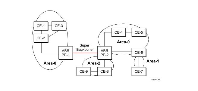
In Figure 7, the PEs are connected to the MPLS-VPN super backbone. In order to be able to distinguish if two OSPF instances are in fact the same and require Type 3 LSAs to be generated, or are two separate routing instances where type 5 external LSAs need to be generated, the concept of a domain-id is introduced.
The domain ID is carried with the MP-BGP update and indicates the source OSPF Domain. When the routes are being redistributed into the same OSPF Domain, the concepts of super backbone described above apply and Type 3 LSAs are generated. If the OSPF domain does not match, then the route type will be external.
Configuring the super backbone (not the sham links) makes all destinations learned by PEs with matching domain IDs inter-area routes.
When configuring sham links, these links become intra-area routes if they are present in the same area.
 
Sham Links
Figure 8: Sham Links
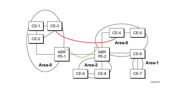
Figure 8 displays the red link between CE-3 and CE-4 could be a low speed OC-3/STM-1 link but because it establishes a intra-area route connection between the CE-3 and CE-4 the potentially high-speed PE-1 to PE-2 connection will not be utilized. Even with a super backbone configuration it is regarded as a inter-area connection.
The establishment of the (green) sham-link is also constructed as an intra-area link between PE routers, a normal OSPF adjacency is formed and the link-state database is exchanged across the MPLS-VPRN. As a result, the desired intra-area connectivity is created, at this time the cost of the green and red links can be managed such that the red link becomes a standby link only in case the VPN fails.
As the shamlink forms an adjacency over the MPLS-VPRN backbone network, be aware that when protocol-protection is enabled in the config>sys>security>cpu-protection>protocol-protection context, the operator must explicit allow the OSPF packets to be received over the backbone network. This performed using the allow-sham-links parameter of the protocol-protection command.
 
 
Implementing the OSPF Super Backbone
With the OSPF super backbone architecture, the continuity of OSPF routing is preserved:
A BGP extended community (OSPF domain ID) provides the source domain of the route. This domain ID is not carried by OSPF but carried by MP-BGP as an extended community attribute.
If the configured extended community value matches the receiving OSPF domain, then the OSPF super backbone is implemented.
From a BGP perspective, the cost is copied into the MED attribute.
 
Loop Avoidance
If a route sent from a PE router to a CE router could then be received by another PE router from one of its own CE routers then it is possible for routing loops to occur. RFC 4577 specifies several methods of loop avoidance.
 
DN-BIT
When a Type 3 LSA is sent from a PE router to a CE router, the DN bit in the LSA options field is set. This is used to ensure that if any CE router sends this Type 3 LSA to a PE router, the PE router will not redistribute it further.
When a PE router needs to distribute to a CE router a route that comes from a site outside the latter's OSPF domain, the PE router presents itself as an ASBR (Autonomous System Border Router), and distributes the route in a type 5 LSA. The DN bit MUST be set in these LSAs to ensure that they will be ignored by any other PE routers that receive them.
DN-BIT loop avoidance is also supported.
Route Tag
If a particular VRF in a PE is associated with an instance of OSPF, then by default it is configured with a special OSPF route tag value called the VPN route tag. This route tag is included in the Type 5 LSAs that the PE originates and sends to any of the attached CEs. The configuration and inclusion of the VPN Route Tag is required for backward compatibility with deployed implementations that do not set the DN bit in Type 5 LSAs.
 
Sham Links
A sham link is only required if a backdoor link (shown as the red link in Figure 8) is present, otherwise configuring an OSPF super backbone will probably suffice.
 
OSPFv3 Authentication
OSPFv3 authentication requires IPv6 IPsec and supports the following:
To pass OSPFv3 authentication, OSPFv3 peers must have matching inbound and outbound SAs configured using the same SA parameters (SPI, keys, etc.). THe implementation must allow the use of one SA for both inbound and outbound directions.
This feature is supported on IES and VPRN interfaces as well as on virtual links.
The re-keying procedure defined in RFC 4552, Authentication/Confidentiality for OSPFv3, supports the following:
The key rollover procedure automatically starts when the operator changes the configuration of the inbound static-sa or bi-directional static-sa under an interface or virtual link. Within the KeyRolloverInterval time period, OSPF3 accepts packets with both the previous inbound static-sa and the new inbound static-sa, and the previous outbound static-sa should continue to be used. When the timer expires, OSPF3 will only accept packets with the new inbound static-sa and for outgoing OSPF3 packets, the new outbound static-sa will be used instead.
 
OSPFv3 Graceful Restart Helper
This feature extends the Graceful Restart helper function supported under other protocols to OSPFv3.
The primary difference between graceful restart helper for OSPFv2 and OSPFv3 is in OSPFv3 a different grace-LSA format is used.
As the SR-OS platforms can support a fully non-stop routing model for control plane high availability the SR-OS node has no need for graceful restart as defined by the IETF in various RFCs for each routing protocol. However, since the 7x50 does need to co-exist in multi-vendor networks and other routers do not always support a true non-stop routing model with stateful failover between routing control planes, there is a need to support a Graceful Restart Helper function.
Graceful restart helper mode allows the SROS based system to provide other routers which have requested it, a grace period, during which the SR-OS systems will continue to use routes authored by or transiting the router requesting the grace period. This is typically used when another router is rebooting the control plane but the forwarding plane is expected to continue to forward traffic based on the previously available FIB.
Figure 9 displays the Graceful OSPF restart (GRACE) LSA format. See section 2.2 of RFC 5187, OSPFv3 Graceful Restart.
 
        0                   1                   2                   3
        0 1 2 3 4 5 6 7 8 9 0 1 2 3 4 5 6 7 8 9 0 1 2 3 4 5 6 7 8 9 0 1
       +-+-+-+-+-+-+-+-+-+-+-+-+-+-+-+-+-+-+-+-+-+-+-+-+-+-+-+-+-+-+-+-+
       |           LS age              |0|0|0|          11             |
       +-+-+-+-+-+-+-+-+-+-+-+-+-+-+-+-+-+-+-+-+-+-+-+-+-+-+-+-+-+-+-+-+
       |                       Link State ID                           |
       +-+-+-+-+-+-+-+-+-+-+-+-+-+-+-+-+-+-+-+-+-+-+-+-+-+-+-+-+-+-+-+-+
       |                    Advertising Router                         |
       +-+-+-+-+-+-+-+-+-+-+-+-+-+-+-+-+-+-+-+-+-+-+-+-+-+-+-+-+-+-+-+-+
       |                    LS sequence number                         |
       +-+-+-+-+-+-+-+-+-+-+-+-+-+-+-+-+-+-+-+-+-+-+-+-+-+-+-+-+-+-+-+-+
       |        LS checksum            |            Length             |
       +-+-+-+-+-+-+-+-+-+-+-+-+-+-+-+-+-+-+-+-+-+-+-+-+-+-+-+-+-+-+-+-+
       |                                                               |
       +-                            TLVs                             -+
       |                             ...                               |
Figure 9: GRACE LSA Format


The Link State ID of a grace-LSA in OSPFv3 is the Interface ID of the interface originating the LSA.
The format of each TLV is:
 
        0                   1                   2                   3
        0 1 2 3 4 5 6 7 8 9 0 1 2 3 4 5 6 7 8 9 0 1 2 3 4 5 6 7 8 9 0 1
       +-+-+-+-+-+-+-+-+-+-+-+-+-+-+-+-+-+-+-+-+-+-+-+-+-+-+-+-+-+-+-+-+
       |              Type             |             Length            |
       +-+-+-+-+-+-+-+-+-+-+-+-+-+-+-+-+-+-+-+-+-+-+-+-+-+-+-+-+-+-+-+-+
       |                            Value...                           |
       +-+-+-+-+-+-+-+-+-+-+-+-+-+-+-+-+-+-+-+-+-+-+-+-+-+-+-+-+-+-+-+-+
 
                                TLV Format
 
Grace-LSA TLVs are formatted according to section 2.3.2 of RFC 3630, Traffic Engineering (TE) Extensions to OSPF Version 2. The Grace-LSA TLVs are used to carry the Grace period (type 1) and the reason the router initiated the graceful restart process (type 2).
Other information in RFC 5187 is directed to routers that require the full graceful restart mechanism as they do not support a stateful transition from primary or backup control plane module (CPM).


Virtual Links
The backbone area in an OSPF AS must be contiguous and all other areas must be connected to the backbone area. Sometimes, this is not possible. You can use virtual links to connect to the backbone through a non-backbone area.
Figure 6 depicts routers Y and Z as the start and end points of the virtual link while area 0.0.0.4 is the transit area. In order to configure virtual links, the router must be an ABR. Virtual links are identified by the router ID of the other endpoint, another ABR. These two endpoint routers must be attached to a common area, called the transit area. The area through which you configure the virtual link must have full routing information.
Transit areas pass traffic from an area adjacent to the backbone or to another area. The traffic does not originate in, nor is it destined for, the transit area. The transit area cannot be a stub area or a NSSA area.
Virtual links are part of the backbone, and behave as if they were unnumbered point-to-point networks between the two routers. A virtual link uses the intra-area routing of its transit area to forward packets. Virtual links are brought up and down through the building of the shortest-path trees for the transit area.
 
Neighbors and Adjacencies
A router uses the OSPF Hello protocol to discover neighbors. A neighbor is a router configured with an interface to a common network. The router sends hello packets to a multicast address and receives hello packets in return.
In broadcast networks, a designated router and a backup designated router are elected. The designated router is responsible for sending link-state advertisements (LSAs) describing the network, which reduces the amount of network traffic.
The routers attempt to form adjacencies. An adjacency is a relationship formed between a router and the designated or backup designated router. For point-to-point networks, no designated or backup designated router is elected. An adjacency must be formed with the neighbor.
To significantly improve adjacency forming and network convergence, a network should be configured as point-to-point if only two routers are connected, even if the network is a broadcast media such as Ethernet.
When the link-state databases of two neighbors are synchronized, the routers are considered to be fully adjacent. When adjacencies are established, pairs of adjacent routers synchronize their topological databases. Not every neighboring router forms an adjacency. Routing protocol updates are only sent to and received from adjacencies. Routers that do not become fully adjacent remain in the two-way neighbor state.
 
Link-State Advertisements
Link-state advertisements (LSAs) describe the state of a router or network, including router interfaces and adjacency states. Each LSA is flooded throughout an area. The collection of LSAs from all routers and networks form the protocol's topological database.
The distribution of topology database updates take place along adjacencies. A router sends LSAs to advertise its state according to the configured interval and when the router's state changes. These packets include information about the router's adjacencies, which allows detection of non-operational routers.
When a router discovers a routing table change or detects a change in the network, link state information is advertised to other routers to maintain identical routing tables. Router adjacencies are reflected in the contents of its link state advertisements. The relationship between adjacencies and the link states allow the protocol to detect non-operating routers. Link state advertisements flood the area. The flooding mechanism ensures that all routers in an area have the same topological database. The database consists of the collection of LSAs received from each router belonging to the area.
OSPF sends only the part that has changed and only when a change has taken place. From the topological database, each router constructs a tree of shortest paths with itself as root. OSPF distributes routing information between routers belonging to a single AS.
 
Metrics
In OSPF, all interfaces have a cost value or routing metric used in the OSPF link-state calculation. A metric value is configured based on hop count, bandwidth, or other parameters, to compare different paths through an AS. OSPF uses cost values to determine the best path to a particular destination: the lower the cost value, the more likely the interface will be used to forward data traffic.
Costs are also associated with externally derived routing data, such as those routes learned from the Exterior Gateway Protocol (EGP), like BGP, and is passed transparently throughout the AS. This data is kept separate from the OSPF protocol's link state data. Each external route can be tagged by the advertising router, enabling the passing of additional information between routers on the boundaries of the AS.
 
Authentication
All OSPF protocol exchanges can be authenticated. This means that only trusted routers can participate in autonomous system routing. Alcatel-Lucent’s implementation of OSPF supports plain text and Message Digest 5 (MD5) authentication (also called simple password).
MD5 allows an authentication key to be configured per network. Routers in the same routing domain must be configured with the same key. When the MD5 hashing algorithm is used for authentication, MD5 is used to verify data integrity by creating a 128-bit message digest from the data input. It is unique to that data. Alcatel-Lucent’s implementation of MD5 allows the migration of an MD5 key by using a key ID for each unique key.
By default, authentication is not enabled on an interface.
 
IP Subnets
OSPF enables the flexible configuration of IP subnets. Each distributed OSPF route has a destination and mask. A network mask is a 32-bit number that indicates the range of IP addresses residing on a single IP network/subnet. This specification displays network masks as hexadecimal numbers; for example, the network mask for a class C IP network is displayed as 0xffffff00. Such a mask is often displayed as 255.255.255.0.
Two different subnets with same IP network number have different masks, called variable length subnets. A packet is routed to the longest or most specific match. Host routes are considered to be subnets whose masks are all ones (0xffffffff).
 
Preconfiguration Recommendations
Prior to configuring OSPF, the router ID must be available. The router ID is a 32-bit number assigned to each router running OSPF. This number uniquely identifies the router within an AS. OSPF routers use the router IDs of the neighbor routers to establish adjacencies. Neighbor IDs are learned when Hello packets are received from the neighbor.
Before configuring OSPF parameters, ensure that the router ID is derived by one of the following methods:
Define the value in the config>router router-id context.
Define the system interface in the config>router>interface ip-int-name context (used if the router ID is not specified in the config>router router-id context).
A system interface must have an IP address with a 32-bit subnet mask. The system interface is used as the router identifier by higher-level protocols such as OSPF and IS-IS. The system interface is assigned during the primary router configuration process when the interface is created in the logical IP interface context.
 
NOTE: On the BGP protocol level, a BGP router ID can be defined in the config>router>bgp router-id context and is only used within BGP.
 
Multiple OSPF Instances
The main route table manager (RTM) can create multiple instances of OSPF by extending the current creation of an instance. A given interface can only be a member of a single OSPF instance.When an interface is configured in a given domain and needs to be moved to another domain the interface must first be removed from the old instance and re-created in the new instance.
 
Route Export Policies for OSPF
Route policies allow specification of the source OSPF process ID in the from and to parameters in the config>router>policy-options>policy-statement>entry>from context, for example from protocol ospf instance-id.
If an instance-id is specified, only routes installed by that instance are picked up for announcement. If no instance-id is specified, then only routes installed by the base instance is will be announced. The all keyword announces routes installed by all instances of OSPF.
When announcing internal (intra/inter-area) OSPF routes from another process, the default type should be type-1, and metric set to the route metric in RTM. For AS-external routes, by default the route type (type-1/2) should be preserved in the originated LSA, and metric set to the route metric in RTM. By default, the tag value should be preserved when an external OSPF route is announced by another process. All these can be changed with explicit action statements.
Export policy should allow a match criteria based on the OSPF route hierarchy, e.g. only intra-area, only inter-area, only external, only internal (intra/inter-area). There must also be a possibility to filter based on existing tag values.
 
Preventing Route Redistribution Loops
The legacy method for this was to assign a tag value to each OSPF process and mark each external route originated within that domain with that value. However, since the tag value must be preserved throughout different OSPF domains, this only catches loops that go back to the originating domain and not where looping occurs in a remote set of domains. To prevent this type of loop, the route propagation information in the LSA must be accumulative. The following method has been implemented:
From the CLI perspective, this involves adding a set of from tag and action tag commands that allow for bit operations.
 
Multi-Address Support for OSPFv3
While OSPFv3 was originally designed to carry only IPv6 routing information, the protocol has been extended to add support for other address families through work within the IETF (RFC 5838). These extensions within the SROS allow separate OSPFv3 instances to be used for IPv6 or IPv4 routing information.
To configure an OSPFv3 instance to distribute IPv4 routing information, a specific OSPFv3 instance must be configured using an instance ID within the range specified by the RFC. For unicast IPv4, the range is 64 to 95.
The following shows the basic configuration steps needed to create the OSPFv3 (ospf3) instance to carry IPv4 routing information. Once the instance is created, the OSPFv3 instance can be configured as needed for the associated network areas, interfaces, and other protocol attributes as you would for OSPFv2.
For example,
config 
   router
       ospf3 64 10.20.1.3
 
IP Fast-reroute (IP FRR) For OSPF and IS-IS Prefixes
This feature provides for the use of the Loop-Free Alternate (LFA) backup next-hop for forwarding in-transit and CPM generated IP packets when the primary next-hop is not available. This means that a node resumes forwarding IP packets to a destination prefix without waiting for the routing convergence.
When any of the following events occurs, IGP instructs in the fast path the IOM to enable the LFA backup next-hop:
IP FRR is supported on IPv4 and IPv6 OSPF/IS-IS prefixes forwarded in the base router instance to a network IP interface or to an IES SAP interface or spoke interface. It is also supported for VPRN VPN-IPv4 OSPF prefixes and VPN-IPv6 OSPF prefixes forwarded to a VPRN SAP interface or spoke interface.
IP FRR also provides a LFA backup next-hop for the destination prefix of a GRE tunnel used in an SDP or in VPRN auto-bind.
The LFA next-hop pre-computation by IGP is described in RFC 5286 – “Basic Specification for IP Fast Reroute: Loop-Free Alternates”.
 
IP FRR Configuration
The user first enables Loop-Free Alternate (LFA) computation by SPF under the IS-IS routing protocol level or under the OSPF routing protocol instance level:
config>router>isis>loopfree-alternate
config>router>ospf>loopfree-alternate
config>service>vprn>ospf>loopfree-alternate
The above commands instruct the IGP SPF to attempt to pre-compute both a primary next-hop and an LFA next-hop for every learned prefix. When found, the LFA next-hop is populated into the RTM along with the primary next-hop for the prefix.
Next the user enables IP FRR to cause RTM to download to IOM a LFA next-hop, when found by SPF, in addition to the primary next-hop for each prefix in the FIB.
config>router>ip-fast-reroute
 
Reducing the Scope of the LFA Calculation by SPF
The user can instruct IGP to not include all interfaces participating in a specific IS-IS level or OSPF area in the SPF LFA computation. This provides a way of reducing the LFA SPF calculation where it is not needed.
config>router>isis>level>loopfree-alternate-exclude
config>router>ospf>area>loopfree-alternate-exclude
The user can also exclude a specific IP interface from being included in the LFA SPF computation by IS-IS or OSPF:
config>router>isis>interface> loopfree-alternate-exclude
config>router>ospf>area>interface> loopfree-alternate-exclude
Note that when an interface is excluded from the LFA SPF in IS-IS, it is excluded in both level 1 and level 2. When the user excludes an interface from the LFA SPF in OSPF, it is excluded in all areas. However, the above OSPF command can only be executed under the area in which the specified interface is primary and once enabled, the interface is excluded in that area and in all other areas where the interface is secondary. If the user attempts to apply it to an area where the interface is secondary, the command will fail.
Finally, the user can apply the same above commands for an OSPF instance within a VPRN service:
config>service>vprn>ospf>area>loopfree-alternate-exclude
config>service>vprn>ospf>area>interface>loopfree-alternate-exclude
 
ECMP Considerations
Whenever the SPF computation determined there is more than one primary next-hop for a prefix, it will not program any LFA next-hop in RTM. Thus, IP prefixes will resolve to the multiple primary next-hops in this case which provides the required protection.
 
IP FRR and RSVP Shortcut (IGP Shortcut)
When both IGP shortcut and LFA are enabled in IS-IS or OSPF, and IP FRR is also enabled, then the following additional IP FRR are supported:
The LFA SPF is extended to use IGP shortcuts as LFA next-hops as explained in OSPF and IS-IS Support for Loop-Free Alternate Calculation .
 
IP FRR and BGP Next-Hop Resolution
An LFA backup next-hop will be able to protect the primary next-hop to reach a prefix advertised by a BGP neighbor. The BGP next-hop will thus remain up when the FIB switches from the primary IGP next-hop to the LFA IGP next-hop.
 
OSPF and IS-IS Support for Loop-Free Alternate Calculation
SPF computation in IS-IS and OSPF is enhanced to compute LFA alternate routes for each learned prefix and populate it in RTM.
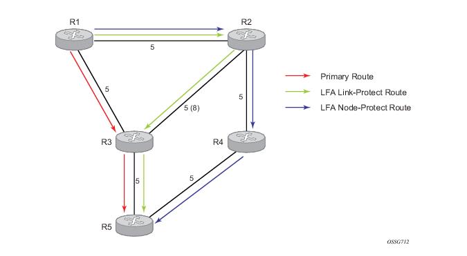
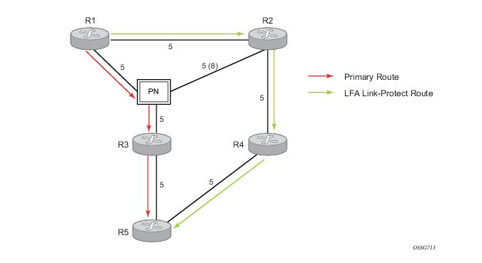
Figure 10 illustrates a simple network topology with point-to-point (P2P) interfaces and highlights three routes to reach router R5 from router R1.
Figure 10: Example Topology with Primary and LFA Routes
The primary route is via R3. The LFA route via R2 has two equal cost paths to reach R5. The path by way of R3 protects against failure of link R1-R3. This route is computed by R1 by checking that the cost for R2 to reach R5 by way of R3 is lower than the cost by way of routes R1 and R3. This condition is referred to as the “loop-free criterion”.
The path by way of R2 and R4 can be used to protect against the failure of router R3. However, with the link R2-R3 metric set to 5, R2 sees the same cost to forward a packet to R5 by way of R3 and R4. Thus R1 cannot guarantee that enabling the LFA next-hop R2 will protect against R3 node failure. This means that the LFA next-hop R2 provides link-protection only for prefix R5. If the metric of link R2-R3 is changed to 8, then the LFA next-hop R2 provides node protection since a packet to R5 will always go over R4.In other words it is required that R2 becomes loop-free with respect to both the source node R1 and the protected node R3.
 
Consider now the case where the primary next-hop uses a broadcast interface as illustrated in Figure 11.
Figure 11: Example Topology with Broadcast Interfaces
In order for next-hop R2 to be a link-protect LFA for route R5 from R1, it must be loop-free with respect to the R1-R3 link Pseudo-Node (PN). However, since R2 has also a link to that PN, its cost to reach R5 by way of the PN, or router R4 are the same. Thus R1 cannot guarantee that enabling the LFA next-hop R2 will protect against a failure impacting link R1-PN since this may cause the entire subnet represented by the PN to go down. If the metric of link R2-PN is changed to 8, then R2 next-hop will be an LFA providing link protection.
 
The following are the detailed equations for this criterion as provided in RFC 5286, Basic Specification for IP Fast Reroute: Loop-Free Alternates:
Rule 1: Link-protect LFA backup next-hop (primary next-hop R1-R3 is a P2P interface):
Distance_opt(R2, R5) < Distance_opt(R2, R1) + Distance_opt(R1, R5)
and,
Distance_opt(R2, R5) >= Distance_opt(R2, R3) + Distance_opt(R3, R5)
Rule 2: Node-protect LFA backup next-hop (primary next-hop R1-R3 is a P2P interface):
Distance_opt(R2, R5) < Distance_opt(R2, R1) + Distance_opt(R1, R5)
and,
Distance_opt(R2, R5) < Distance_opt(R2, R3) + Distance_opt(R3, R5)
Rule 3: Link-protect LFA backup next-hop (primary next-hop R1-R3 is a broadcast interface):
Distance_opt(R2, R5) < Distance_opt(R2, R1) + Distance_opt(R1, R5)
and,
Distance_opt(R2, R5) < Distance_opt(R2, PN) + Distance_opt(PN, R5)
where; PN stands for the R1-R3 link Pseudo-Node.
For the case of P2P interface, if SPF finds multiple LFA next-hops for a given primary next-hop, it follows the following selection algorithm:
A)
B)
C)
For the case of a broadcast interface, a node-protect LFA is not necessarily a link protect LFA if the path to the LFA next-hop goes over the same PN as the primary next-hop. Similarly, a link protect LFA may not guarantee link protection if it goes over the same PN as the primary next-hop. The selection algorithm when SPF finds multiple LFA next-hops for a given primary next-hop is modified as follows:
A)
The first set consists of LFA next-hops which do not go over the PN used by primary next-hop.
The second set consists of LFA next-hops which do go over the PN used by the primary next-hop.
B)
C)
D)
E)
Note this algorithm is more flexible than strictly applying Rule 3 above; i.e., the link protect rule in the presence of a PN and specified in RFC 5286. A node-protect LFA which does not avoid the PN; i.e., does not guarantee link protection, can still be selected as a last resort. The same thing, a link-protect LFA which does not avoid the PN may still be selected as a last resort.
Both the computed primary next-hop and LFA next-hop for a given prefix are programmed into RTM.
 
Loop-Free Alternate Calculation in the Presence of IGP shortcuts
In order to expand the coverage of the LFA backup protection in a network, RSVP LSP based IGP shortcuts can be placed selectively in parts of the network and be used as an LFA backup next-hop.
When IGP shortcut is enabled in IS-IS or OSPF on a given node, all RSVP LSP originating on this node and with a destination address matching the router-id of any other node in the network are included in the main SPF by default.
In order to limit the time it takes to compute the LFA SPF, the user must explicitly enable the use of an IGP shortcut as LFA backup next-hop using one of a couple of new optional argument for the existing LSP level IGP shortcut command:
config>router>mpls>lsp>igp-shortcut [lfa-protect | lfa-only]
The lfa-protect option allows an LSP to be included in both the main SPF and the LFA SPFs. For a given prefix, the LSP can be used either as a primary next-hop or as an LFA next-hop but not both. If the main SPF computation selected a tunneled primary next-hop for a prefix, the LFA SPF will not select an LFA next-hop for this prefix and the protection of this prefix will rely on the RSVP LSP FRR protection. If the main SPF computation selected a direct primary next-hop, then the LFA SPF will select an LFA next-hop for this prefix but will prefer a direct LFA next-hop over a tunneled LFA next-hop.
The lfa-only option allows an LSP to be included in the LFA SPFs only such that the introduction of IGP shortcuts does not impact the main SPF decision. For a given prefix, the main SPF always selects a direct primary next-hop. The LFA SPF will select a an LFA next-hop for this prefix but will prefer a direct LFA next-hop over a tunneled LFA next-hop.
Thus the selection algorithm in Section 1.3 when SPF finds multiple LFA next-hops for a given primary next-hop is modified as follows:
A)
B)
C)
D)
E)
F)
G)
H)
 
Loop-Free Alternate Calculation for Inter-Area/inter-Level Prefixes
When SPF resolves OSPF inter-area prefixes or IS-IS inter-level prefixes, it will compute an LFA backup next-hop to the same exit area/border router as used by the primary next-hop.
Loop-Free Alternate Shortest Path First (LFA SPF) Policies
An LFA SPF policy allows the user to apply specific criteria, such as admin group and SRLG constraints, to the selection of a LFA backup next-hop for a subset of prefixes that resolve to a specific primary next-hop. The feature introduces the concept of route next-hop template to influence LFA backup next-hop selection.
 
Configuration of Route Next-Hop Policy Template
The LFA SPF policy consists of applying a route next-hop policy template to a set of prefixes.
The user first creates a route next-hop policy template under the global router context:
configure>router>route-next-hop-policy>template template-name
A policy template can be used in both IS-IS and OSPF to apply the specific criteria described in the next sub-sections to prefixes protected by LFA. Each instance of IS-IS or OSPF can apply the same policy template to one or more prefix lists and to one or more interfaces.
The commands within the route next-hop policy use the begin-commit-abort model introduced with BFD templates. The following are the steps to create and modify the template:
To delete a template which is not in use, the user enters the no form for the template name under the route-next-hop-policy context.
The user enters the editing mode by executing the begin command under route-next-hop-policy context. The user can then edit and change any number of route next-hop policy templates. However, the parameter value will still be stored temporarily in the template module until the commit is executed under the route-next-hop-policy context. Any temporary parameter changes will be lost if the user enters the abort command before the commit command.
The user is allowed to create or delete a template instantly once in the editing mode without the need to enter the commit command. Furthermore, the abort command if entered will have no effect on the prior deletion or creation of a template.
Once the commit command is issued, IS-IS or OSPF will re-evaluate the templates and if there are any net changes, it will schedule a new LFA SPF to re-compute the LFA next-hop for the prefixes associated with these templates.
 
Configuring Affinity or Admin Group Constraint in Route Next-Hop Policy
Administrative groups (admin groups), also known as affinity, are used to tag IP interfaces which share a specific characteristic with the same identifier. For example, an admin group identifier could represent all links which connect to core routers, or all links which have bandwidth higher than 10G, or all links which are dedicated to a specific service.
The user first configures locally on each router the name and identifier of each admin group:
config>router>if-attribute>admin-group group-name value group-value
A maximum of 32 admin groups can be configured per system.
Next the user configures the admin group membership of the IP interfaces used in LFA. The user can apply admin groups to IES, VPRN, or network IP interface.
config>router> interface>if-attribute>admin-group group-name [group-name...(up to 5 max)]
config>service>ies>interface>if-attribute>admin-group group-name [group-name...(up to 5 max)]
config>service>vprn >interface>if-attribute>admin-group group-name [group-name...(up to 5 max)]
The user can add as many admin groups as configured to a given IP interface. The same above command can be applied multiple times.
Note that the configured admin-group membership will be applied in all levels/areas the interface is participating in. The same interface cannot have different memberships in different levels/areas.
The no form of the admin-group command under the interface deletes one or more of the admin-group memberships of the interface. It deletes all memberships if no group name is specified.
Finally, the user adds the admin group constraint into the route next-hop policy template:
configure router route-next-hop-template template template-name
include-group group-name [pref 1]
include-group group-name [pref 2]
exclude-group group-name
Each group is entered individually. The include-group statement instructs the LFA SPF selection algorithm to pick up a subset of LFA next-hops among the links which belong to one or more of the specified admin groups. A link which does not belong to at least one of the admin-groups is excluded. However, a link can still be selected if it belongs to one of the groups in a include-group statement but also belongs to other groups which are not part of any include-group statement in the route next-hop policy.
The pref option is used to provide a relative preference for the admin group to select. A lower preference value means that LFA SPF will first attempt to select a LFA backup next-hop which is a member of the corresponding admin group. If none is found, then the admin group with the next higher preference value is evaluated. If no preference is configured for a given admin group name, then it is supposed to be the least preferred, i.e., numerically the highest preference value.
When evaluating multiple include-group statements within the same preference, any link which belongs to one or more of the included admin groups can be selected as an LFA next-hop. There is no relative preference based on how many of those included admin groups the link is a member of.
The exclude-group statement simply prunes all links belonging to the specified admin group before making the LFA backup next-hop selection for a prefix.
If the same group name is part of both include and exclude statements, the exclude statement will win. It other words, the exclude statement can be viewed as having an implicit preference value of 0.
Note the admin-group criterion is applied before running the LFA next-hop selection algorithm. The modified LFA next-hop selection algorithm is shown in Section 7.5.
 
Configuring SRLG Group Constraint in Route Next-Hop Policy
Shared Risk Loss Group (SRLG) is used to tag IP interfaces which share a specific fate with the same identifier. For example, an SRLG group identifier could represent all links which use separate fibers but are carried in the same fiber conduit. If the conduit is accidentally cut, all the fiber links are cut which means all IP interfaces using these fiber links will fail. Thus the user can enable the SRLG constraint to select a LFA next-hop for a prefix which avoids all interfaces that share fate with the primary next.
The user first configures locally on each router the name and identifier of each SRLG group:
configure>router>if-attribute>srlg-group group-name value group-value
A maximum of 1024 SRLGs can be configured per system.
Next the user configures the admin group membership of the IP interfaces used in LFA. The user can apply SRLG groups to IES, VPRN, or network IP interface.
config>router>interface>if-attribute>srlg-group group-name [group-name...(up to 5 max)]
config>service>vprn>interface>if-attribute>srlg-group group-name [group-name...(up to 5 max)]
config>service>ies>interface>if-attribute>srlg-group group-name [group-name...(up to 5 max)]
The user can add a maximum of 64 SRLG groups to a given IP interface. The same above command can be applied multiple times.
Note that the configured SRLG membership will be applied in all levels/areas the interface is participating in. The same interface cannot have different memberships in different levels/areas.
The no form of the srlg-group command under the interface deletes one or more of the SRLG memberships of the interface. It deletes all SRLG memberships if no group name is specified.
Finally, the user adds the SRLG constraint into the route next-hop policy template:
configure router route-next-hop-template template template-name
srlg-enable
When this command is applied to a prefix, the LFA SPF will select a LFA next-hop, among the computed ones, which uses an outgoing interface that does not participate in any of the SLRGs of the outgoing interface used by the primary next-hop.
Note the SRLG and admin-group criteria are applied before running the LFA next-hop selection algorithm. The modified LFA next-hop selection algorithm is shown in Section 7.5.
 
Interaction of IP and MPLS Admin Group and SRLG
The LFA SPF policy feature generalizes the use of admin-group and SRLG to other types of interfaces. To that end, it is important that the new IP admin groups and SRLGs be compatible with the ones already supported in MPLS. The following rules are implemented:
Only the admin groups and SRLGs bound to an MPLS interface context or the SRLG database context are advertised in TE link TLVs and sub-TLVs when the traffic-engineering option is enabled in IS-IS or OSPF. IES and VPRN interfaces do not have their attributes advertised in TE TLVs.
 
Configuring Protection Type and Next-Hop Type Preference in Route next-hop policy template
The user can select if link protection or node protection is preferred in the selection of a LFA next-hop for all IP prefixes and LDP FEC prefixes to which a route next-hop policy template is applied. The default in SROS implementation is node protection. The implementation will fall back to the other type if no LFA next-hop of the preferred type is found.
The user can also select if tunnel backup next-hop or IP backup next-hop is preferred. The default in SROS implementation is to prefer IP next-hop over tunnel next-hop. The implementation will fall back to the other type if no LFA next-hop of the preferred type is found.
The following options are thus added into the Route next-hop policy template:
configure router route-nh-template template template-name
protection-type {link | node}
nh-type {ip | tunnel}
When the route next-hop policy template is applied to an IP interface, all prefixes using this interface as a primary next-hop will follow the protection type and next-hop type preference specified in the template.
 
Application of Route Next-Hop Policy Template to an Interface
Once the route next-hop policy template is configured with the desired policies, the user can apply it to all prefixes which primary next-hop uses a specific interface name. The following command is achieves that:
config>router>isis>interface>lfa-policy-map route-nh-template template-name
config>router>ospf(3)>area>interface>lfa-policy-map route-nh-template template-name
config>service>vprn>ospf(3)>area>interface>lfa-policy-map route-nh-template template-name
When a route next-hop policy template is applied to an interface in IS-IS, it is applied in both level 1 and level 2. When a route next-hop policy template is applied to an interface in OSPF, it is applied in all areas. However, the above CLI command in an OSPF interface context can only be executed under the area in which the specified interface is primary and then applied in that area and in all other areas where the interface is secondary. If the user attempts to apply it to an area where the interface is secondary, the command will fail.
If the user excluded the interface from LFA using the command loopfree-alternate-exclude, the LFA policy if applied to the interface has no effect.
Finally, if the user applied a route next-hop policy template to a loopback interface or to the system interface, the command will not be rejected but it will result in no action taken.
 
Excluding Prefixes from LFA SPF
In the current SROS implementation, the user can exclude an interface in IS-IS or OSPF, an OSPF area, or an IS-IS level from the LFA SPF.
This feature adds the ability to exclude prefixes from a prefix policy which matches on prefixes or on IS-IS tags:
config>router>isis>loopfree-alternate-exclude prefix-policy prefix-policy1 [prefix-policy2…up to 5]
config>router>ospf(3)>loopfree-alternate-exclude prefix-policy prefix-policy1 [prefix-policy2…up to 5]
config>service>vprn>ospf(3)>loopfree-alternate-exclude prefix-policy prefix-policy1 [prefix-policy2…up to 5]
The prefix policy is configured as in existing SROS implementation:
config
router
policy-options
[no] prefix-list prefix-list1
prefix 62.225.16.0/24 prefix-length-range 32-32
[no] policy-statements prefix-policy1
entry 10
from
prefix-list "prefix-list1"
exit
action accept
exit
exit
default-action reject
exit	
If the user enabled the R12 IS-IS prefix prioritization based on tag, it will also apply to SPF LFA. However, if a prefix is excluded from LFA, then it will not be included in LFA calculation regardless of its priority. The prefix tag will however be used in the main SPF. Note that prefix tags are not defined for OSPF protocol.
The default action of the above loopfree-alternate-exclude command when not explicitly specified by the user in the prefix policy is a “reject”. Thus, regardless if the user did or did not explicitly add the statement “default-action reject” to the prefix policy, a prefix which did not match any entry in the policy will be accepted into LFA SPF.
 
Modification to LFA Next-Hop Selection Algorithm
This feature modifies the LFA next-hop selection algorithm. The SRLG and admin-group criteria are applied before running the LFA next-hop selection algorithm. In other words, links which do not include one or more of the admin-groups in the include-group statements and links which belong to admin-groups which have been explicitly excluded using the exclude-group statement, and the links which belong to the SRLGs used by the primary next-hop of a prefix are first pruned.
Note that this pruning applies only to IP next-hops. Tunnel next-hops can have the admin-group or SRLG constraint applied to them under MPLS. For instance, If a tunnel next-hop is using an outgoing interface which belongs to given SRLG ID, the user can enable the srlg-frr option under ‘config>router>mpls’ context to be sure the RSVP LSP FRR backup LSP will not use an outgoing interface with the same SRLG ID. A prefix which is resolved to a tunnel next-hop is protected by the RSVP FRR mechanism and not by the IP FRR mechanism. Similarly, the user can include or exclude admin-groups for the RSVP LSP and its FRR bypass backup LSP in MPLS context. Note however the admin-group constraints will be applied to the selection of the outgoing interface of both the LSP primary path and its FRR bypass backup path.
The following is the modified LFA selection algorithm which is applied to prefixes resolving to a primary next-hop which uses a given route next-hop policy template. The changes are highlighted in yellow color.
links which do not include one or more of the admin-groups in the include-group statements in the route next-hop policy template.
links which belong to admin-groups which have been explicitly excluded using the exclude-group statement in the route next-hop policy template.
Continue with the set indicated in the nh-type value in the route next-hop policy template if not empty; otherwise continue with the other set.
If same total cost, select lowest router-id.
If same router-id, select lowest interface-index.
If same lowest cost, select tunnel with lowest tunnel-index.
Within selected subset, select lowest total cost of a prefix. For a tunnel next-hop, it means the LSP metric plus the cost of the LSP endpoint to the destination of the prefix.
If same total cost, select lowest endpoint to destination cost
If same endpoint to destination cost, select lowest router-id,
If same router-id, select lowest tunnel-index.
 
OSPF LSA Filtering
The SR-OS OSPF implementation supports a configuration option to filter outgoing OSPF LSAs on selected OSPFv2 or OSPFv3 interfaces. This feature should be used with some caution because it goes against the principle that all OSPF routers in an area should have a synchronized Link State Database (LSDB), but it can be a useful resource saving in certain hub and spoke topologies where learning routes through OSPF is only needed in one direction (for example, from spoke to hub).
Three filtering options are available (configurable per interface):
Segment Routing in Shortest Path Forwarding
OSPF can be configured in Segment Routing in Shortest Path Forwarding using the same procedures as those used to configure IS-IS. See Segment Routing in Shortest Path Forwarding in the IS-IS section for more information.
FIB Prioritization
The RIB processing of specific routes can be prioritized through the use of the rib-priority command. This command allows specific routes to be prioritized through the protocol processing so that updates are propagated to the FIB as quickly as possible.
Configuring the rib-priority command either within the global OSPF or OSPFv3 routing context or under a specific OSPF/OSPFv3 interface context enables this feature. Under the global OSPF context, a prefix list can be specified that identifies which route prefixes should be considered high priority. If the rib-priority high command is configured under an OSPF interface context then all routes learned through that interface is considered high priority.
The routes that have been designated as high priority will be the first routes processed and then passed to the FIB update process so that the forwarding engine can be updated. All known high priority routes should be processed before the OSPF routing protocol moves on to other standard priority routes. This feature will have the most impact when there are a large number of routes being learned through the OSPF routing protocols.
 
OSPF Configuration Process Overview
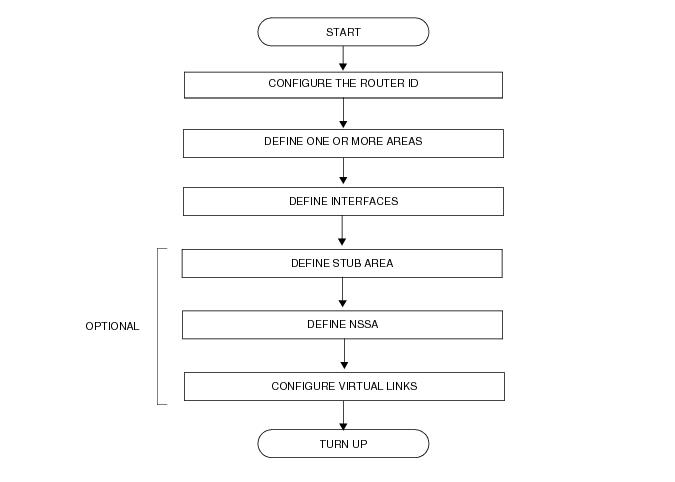
Figure 12 displays the process to provision basic OSPF parameters.
Figure 12: OSPF Configuration and Implementation Flow
Configuration Notes
This section describes OSPF configuration caveats.
 
General
 
OSPF Defaults
The following list summarizes the OSPF configuration defaults: