This section provides information to create subscriber (customer) accounts and configure Service Distribution Points (SDPs) using the command line interface.
A:ALA-B>config>service# info detail
#------------------------------------------
...
sdp 2 gre create
description "GRE-10.10.10.104"
far-end 10.10.10.104
signaling tldp
no vlan-vc-etype
keep-alive
path-mtu 4462
keep-alive
shutdown
hello-time 10
hold-down-time 10
max-drop-count 3
timeout 5
no message-length
exit
no shutdown
exit
...
epipe 6000 customer 6 vpn 6000 create
service-name “customer-ABC-NW” (R8.0)
service-mtu 1514
sap 1/1/2:0 create
no multi-service-site
ingress
no scheduler-policy
qos 1
exit
egress
no scheduler-policy
qos 1
exit
no collect-stats
no accounting-policy
no shutdown
exit
spoke-sdp 2:6111 create
ingress
no vc-label
no filter
exit
egress
no vc-label
no filter
exit
no shutdown
exit
no shutdown
exit
...
#------------------------------------------
A:ALA-B>config>service#
The most basic customer account must have a customer ID. Optional parameters include:
rate pir-rate [cir cir-rate]
A:ALA-12>config>service# info
-------------------------------------------
...
customer 5 create
description "Alcatel Customer"
contact "Technical Support"
phone "650 555-5100"
exit
...
-------------------------------------------
A:A:ALA-12>config>service#
Multi-service sites create a virtual scheduler hierarchy and making it available to queues on multiple Service Access Points (SAPs). The ingress and
egress scheduler-policy commands on the SAP are mutually exclusive with the SAP
multi-service-site command. The multi-service customer site association must be removed from the SAP before local scheduler polices may be applied.
After a multi-service site is created, it must be assigned to a chassis slot or port. Note that the 7750 SR-1 model multi-service site assignment configuration defaults to slot 1.
A:ALA-12>config>service# info
-------------------------------------------
..
customer 5 create
multi-service-site "EastCoast" create
assignment card 4
ingress
scheduler-policy "alpha1"
exit
exit
multi-service-site "WestCoast" create
assignment card 3
egress
scheduler-policy "SLA1"
exit
exit
description "Alcatel Customer"
contact "Technical Support"
phone "650 555-5100"
exit
...
-------------------------------------------
A:ALA-12>config>service#
NOTE: When you specify the far-end ip address, you are creating the tunnel. In essence, you are creating the path from Point A to Point B. When you configure a distributed service, you must identify an SDP ID. Use the show service sdp command to display the qualifying SDPs.
LSPs are configured in the config>router>mpls context. See the
OS MPLS Guide for configuration and command information.
lsp lsp-name [
lsp-name] (only for MPLS SDPs)
A:ALA-12>config>service# info
-------------------------------------------
...
sdp 2 create
description "GRE-10.10.10.104"
far-end 10.10.10.104
keep-alive
shutdown
exit
no shutdown
exit
sdp 8 mpls create
description "MPLS-10.10.10.104"
far-end 10.10.10.104
lsp "to-104"
keep-alive
shutdown
exit
no shutdown
exit
sdp 104 mpls create
description "MPLS-10.10.10.94"
far-end 10.10.10.94
ldp
keep-alive
shutdown
exit
no shutdown
exit
...
-----------------------------------------
A:ALA-12>config>service#
The no form of this command disables the mixed-LSP mode of operation. The user first has to remove one of the LSP types from the SDP configuration or the command will fail.
The BGP LSP type is allowed. The bgp-tunnel command can be configured under the SDP with the
lsp or
ldp commands.
When a higher priority type LSP becomes available, the service manager reverts back to this LSP at the expiry of the sdp-revert-time timer or the failure of the currently active LSP, whichever comes first. The service manager then re-programs the linecard accordingly. If the
infinite value is configured, then the SDP reverts to the highest priority type LSP only if the currently active LSP failed.
If the value of the sdp-revert-time timer is changed, it will take effect only at the next use of the timer. Any timer which is outstanding at the time of the change will be restarted with the new value.
The OS Services Guide will provide the basic service applicable material to build the service specific management points, MEPs and MIPs.
As shown in Figure 30 and
Figure 31, the following functions are supported:
Note: Do not exceed the platform-specific scaling limits. Since a single facility fault may trigger the generation of many service level faults, ensure the specific ETH-CFM processing power of the network element and any configured rate controlling features for the service are not exceed. Exceeding the network element scaling properties may lead to OAM packet loss during processing and result in undesirable behavior.
Facility MEPs are not supported on ports that are configured with Eth-Tunnels (G.8031), and only facility MEPs of 1 second and above are supported on the ports that are involved in an Eth-Ring (G.8032).
It is important to note that AIS operates independently from the low-priority-defect setting. The
low-priority-defect setting configuration parameter affects only the ETH-CFM fault propagation and alarming outside the scope of AIS. Any fault in the MEP state machine generates AIS when it is configured.
Table 3 illustrates the ETH-CC defect condition groups, configured low-priority-defect setting, priority and defect as it applies to fault propagation.
A facility MEP may trigger two distinct actions as a result of fault. Epipe services generate AIS that have been configured to do so as a result of a failure. The level of the AIS is derived from the facility MEP. Multiple client-meg-levels can be configured under the facility MEP to allow for operational efficiency in the event a change is required. However, only the lowest AIS level is generated for all the linked and applicable services. VPLS, IES and VRPN SAPs transition the SAP state that are configured to react to the facility MEP state. In addition, Epipe services may also take advantages of OAM and mapping functions.
|
•
|
Disable the client-meg-level configuration parameter when changes are being made to existing functional facility MEPs for AIS. Doing this stops the transmit function but maintains the ability to receive and understand AIS conditions from the network.
|
|
•
|
Set the low-priority-defect parameter to noXconn in order to prevent the MEP from entering a defect state, triggering SAP transitions and OAM mapping reactions.
|
The ccm-hold-timers supported on port-based MEPs configured with a sub-second interval. The
ccm-hold-timers prevents the MEP from entering a failed state for 3.5 times the CCM interval plus the additional hold timer.
|
•
|
AIS-enable configuration options: Epipe services support the ais-enable configuration option under the SAP hierarchy level. This structure, outside of the MEP context, creates a special link between the Epipe service SAP and the facility MEP. If a facility MEP enters a fault state, all Epipe service SAPs with this configuration generate lowest-level AIS at the level configured under the facility MEP. As with fault propagation, AIS generation is restricted to Epipe services only. The actions taken by the other services is described in more detail in the relevant facility MEP sections.
|
Port facility MEPs are advantageous in cases where port-to-port connectivity issues are obscured., similar to the deployment use cases for IEEE 802.3 Clause 57 – Operation, Administration and Maintenance (formerly 802.3ah).
Clause 57 specification limits the transmit rate to 10pps, or a send rate of 100ms. In order to detect port failure conditions between two peers faster, a port-based facility MEP may be configured to utilize the supported sub-second CCM intervals. Also, 1 second and above timers are available for configuration for cases where aggressive timers are not necessary. Note that all platform-specific requirements must be met for the desired interval. Since both ETH-CFM and IEEE 802.3 Clause 57 attempt to control the port state in event of protocol failure, these two functions are mutually exclusive and can not be configured on the same port.
When a port enters the link up operational state due to ETH-CFM, the MEP continues to transmit and received in order to properly clear the condition. However, when the port fails for reasons that are not specific to ETH-CFM, it stops transmit and receive functions until the condition is cleared. This is different than the behavior of a service MEP, because facility MEPs only supports
Down MEPs, while some service-based MEPs support
UP and
Down MEPs. In the case of
UP MEPs, a single port failure may not prevent all the CCMs from egressing the node. So the operational method for service-based MEPs remains the same: continuing to increase the counter for CCM transmit in the event of port failure, regardless of the reason. The transmit ETH-CCM counters do not apply to sub-second CCM-enabled MEPs.
When a port-based facility MEP causes the port to enter the operational state Link Up, normal processing occurs for all higher level functions. If the port is a member port, unless the entire LAG enters a non-operational state, the SAP configured on the LAG remains operational. A facility MEP on a member port has no direct influence on the SAP. The purpose of a facility MEP on a member port is to provide feedback to the LAG. The LAG performs the normal computations in response to a port down condition. A facility MEP configured on a non-member port does have direct control over the SAPs configured on the port. Therefore, when a port fails, all the SAPs transitions to the operation state
down. When this occurs, fault may be propagated using AIS for those Epipe services that are AIS-enabled under the SAO. For the services that have MEPs configured on the SAP or the binding, fault propagation occurs. For VPLS, IES and VPRN services, normal reaction to a SAP entering a
down state occurs.
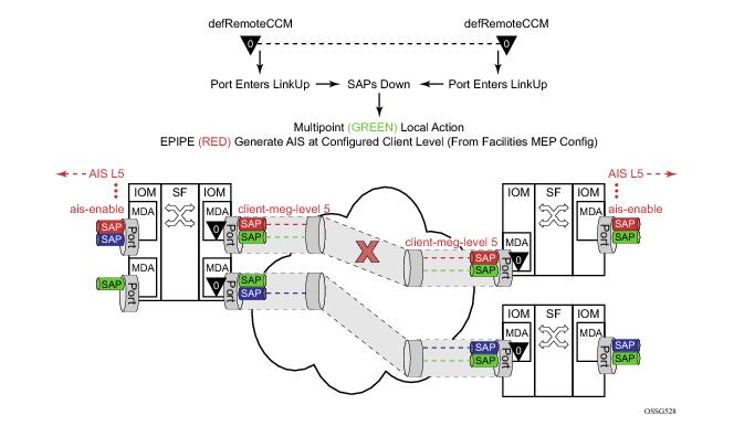
Figure 32 provides an example of how an ETH-CFM failure reacts with the various services that share that port. The green Epipe service generates AIS as a result of the port failure using the
client-meg-level command configured on the port facility MEP. The multipoint service takes location configured action when the SAP transitions to the
down operational state. The blue Epipe service is not affected by the port
link up state as a result of ETH-CFM fault.
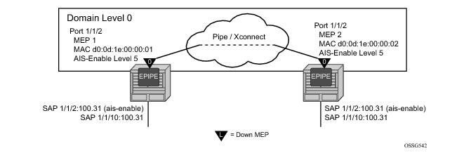
The following illustration, Figure 33, provides an example of how port-based MEPs and defect conditions translate into service awareness without service-based MEPs. From the two nodes perspective, they are aware they are directly connected at the port. The two nodes are unaware of any of the cross connections that allow this to occur.
Configure port-based MEPs with the facility-fault option and
ais-enable client-meg-level command. When the MEP enters any defect state, an AIS is generated to any Epipe service that has the
ais-enable configured under the
sap>eth-cfm hierarchy.
NODE1
config>eth-cfm# info
----------------------------------------------
domain 10 format none level 0
association 1 format icc-based name "FacilityPort0"
ccm-interval 1
remote-mepid 2
exit
exit
----------------------------------------------
config>port# info
----------------------------------------------
ethernet
mode access
encap-type qinq
eth-cfm
mep 1 domain 10 association 1
ais-enable
client-meg-level 5
exit
facility-fault
ccm-enable
mac-address d0:0d:1e:00:00:01
no shutdown
exit
exit
exit
no shutdown
----------------------------------------------
config>service>epipe# info
----------------------------------------------
sap 1/1/2:100.31 create
eth-cfm
ais-enable
exit
exit
sap 1/1/10:100.31 create
exit
no shutdown
----------------------------------------------
NODE2
config>eth-cfm# info
----------------------------------------------
domain 10 format none level 0
association 1 format icc-based name "FacilityPort0"
ccm-interval 1
remote-mepid 1
exit
exit
----------------------------------------------
config>port# info
----------------------------------------------
ethernet
mode access
encap-type qinq
eth-cfm
mep 2 domain 10 association 1
ais-enable
client-meg-level 5
exit
facility-fault
ccm-enable
mac-address d0:0d:1e:00:00:02
no shutdown
exit
exit
exit
no shutdown
----------------------------------------------
config>service>epipe# info
----------------------------------------------
sap 1/1/2:100.31 create
eth-cfm
ais-enable
exit
exit
sap 1/1/10:100.31 create
exit
no shutdown
----------------------------------------------
If the low-priority-defect is left at the default macRemErrXcon setting, then port state may not match on both nodes. If an unidirectional failure is introduced for port-based MEPs, then RDI is received on one of the nodes and the other node would report and react to RemoteCCM (timeout). The RDI defect is below the default
low-priority-defect in priority, and the port would remain operationally UP and the port state would remain UP. The MEP that has timed out the peer MEP takes port level action because this defect is higher in priority than the default low-priority-defect. The port state is recorded as
Link Up and the Port is operationally down with a
Reason Down : ethCfmFault. To avoid this inconsistency, set the
low-priority-defect setting to detection unidirectional failures using the
allDef option.
NODE1
#show port
===============================================================================
Ports on Slot 1
===============================================================================
Port Admin Link Port Cfg Oper LAG/ Port Port Port C/QS/S/XFP/
Id State State MTU MTU Bndl Mode Encp Type MDIMDX
-------------------------------------------------------------------------------
…snip..
1/1/2 Up Yes Up 1522 1522 - accs qinq xcme
…snip..
#show port 1/1/2
===============================================================================
Ethernet Interface
===============================================================================
Description : 10/100/Gig Ethernet SFP
Interface : 1/1/2 Oper Speed : 1 Gbps
Link-level : Ethernet Config Speed : 1 Gbps
Admin State : up Oper Duplex : full
Oper State : up Config Duplex : full
Physical Link : Yes MTU : 1522
…snip…
#show eth-cfm mep 1 domain 10 association 1
===============================================================================
Eth-Cfm MEP Configuration Information
===============================================================================
Md-index : 10 Direction : Down
Ma-index : 1 Admin : Enabled
MepId : 1 CCM-Enable : Disabled
Port : 1/1/2 VLAN : 0
Description : (Not Specified)
FngState : fngReset ControlMep : False
LowestDefectPri : macRemErrXcon HighestDefect : none
Defect Flags : bDefRDICCM
Mac Address : d0:0d:1e:00:00:01 ControlMep : False
CcmLtmPriority : 7
CcmTx : 1481 CcmSequenceErr : 0
Fault Propagation : disabled FacilityFault : Notify
MA-CcmInterval : 1 MA-CcmHoldTime : 0ms
Eth-1Dm Threshold : 3(sec) MD-Level : 0
Eth-Ais: : Enabled Eth-Ais Rx Ais: : No
Eth-Ais Tx Priorit*: 7 Eth-Ais Rx Interv*: 1
Eth-Ais Tx Interva*: 1 Eth-Ais Tx Counte*: 3019
Eth-Ais Tx Levels : 5
Eth-Tst: : Disabled
…snip…
# show service sap-using eth-cfm facility
===============================================================================
Service ETH-CFM Facility Information
===============================================================================
SapId SvcId SAP AIS SAP Tunnel SVC Tunnel
Fault Fault
-------------------------------------------------------------------------------
1/1/2:100.31 100 Enabled Accept Ignore
-------------------------------------------------------------------------------
No. of Facility SAPs: 1
===============================================================================
NODE2
# show port
===============================================================================
Ports on Slot 1
===============================================================================
Port Admin Link Port Cfg Oper LAG/ Port Port Port C/QS/S/XFP/
Id State State MTU MTU Bndl Mode Encp Type MDIMDX
-------------------------------------------------------------------------------
…snip..
1/1/2 Up Yes Link Up 1522 1522 - accs qinq xcme
…snip..
# show port 1/1/2
===============================================================================
Ethernet Interface
===============================================================================
Description : 10/100/Gig Ethernet SFP
Interface : 1/1/2 Oper Speed : N/A
Link-level : Ethernet Config Speed : 1 Gbps
Admin State : up Oper Duplex : N/A
Oper State : down Config Duplex : full
Reason Down : ethCfmFault
Physical Link : Yes MTU : 1522
…snip…
# show eth-cfm mep 2 domain 10 association 1
===============================================================================
Eth-Cfm MEP Configuration Information
===============================================================================
Md-index : 10 Direction : Down
Ma-index : 1 Admin : Enabled
MepId : 2 CCM-Enable : Enabled
Port : 1/1/2 VLAN : 0
Description : (Not Specified)
FngState : fngDefectReported ControlMep : False
LowestDefectPri : macRemErrXcon HighestDefect : defRemoteCCM
Defect Flags : bDefRemoteCCM
Mac Address : d0:0d:1e:00:00:02 ControlMep : False
CcmLtmPriority : 7
CcmTx : 5336 CcmSequenceErr : 0
Fault Propagation : disabled FacilityFault : Notify
MA-CcmInterval : 1 MA-CcmHoldTime : 0ms
Eth-1Dm Threshold : 3(sec) MD-Level : 0
Eth-Ais: : Enabled Eth-Ais Rx Ais: : No
Eth-Ais Tx Priorit*: 7 Eth-Ais Rx Interv*: 1
Eth-Ais Tx Interva*: 1 Eth-Ais Tx Counte*: 3515
Eth-Ais Tx Levels : 5
Eth-Tst: : Disabled
…snip…
# show service sap-using eth-cfm facility
===============================================================================
Service ETH-CFM Facility Information
===============================================================================
SapId SvcId SAP AIS SAP Tunnel SVC Tunnel
Fault Fault
-------------------------------------------------------------------------------
1/1/2:100.31 100 Enabled Accept Ignore
-------------------------------------------------------------------------------
No. of Facility SAPs: 1
===============================================================================
LAG bundled ports provide both protection and scalability. Down MEPs configured on a LAG validates the connectivity of the LAG. Failure of this MEP causes the LAG to enter an operational down state. SAPs connected to the operationally
down LAG transitions to operationally
down. This triggers the configured reaction and processing similar to that of the port-based facility MEP. AIS is generated for those Epipe services with AIS enabled under the SAP. Local processing occurs for VPLS, IES and VPRN services that have experienced the SAP failure as a result of the LAG based SAP. Furthermore, fault propagation is invoked for any SAP with fault propagation operations enabled as a result of the failed LAG based SAP. LAG-based MEPs must be configured with a direction
down.
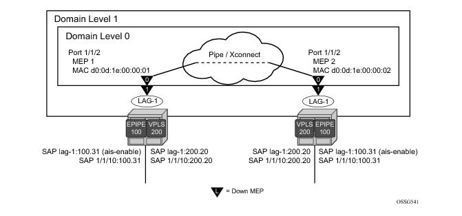
Figure 34 , provides an example how an ETH-CFM failure reacts with the various services that share that LAG. There is only one way the LAG state can trigger the propagation of failure, and that is using ETH-AIS. The carrier must enable CCM at the LAG level and a ETH-CCM defect condition exists. The red Epipe service generates AIS as a result of the LAG failure using the
client-meg-level parameter configured on the LAG facility MEP. The green multipoint service takes location-configured action when the SAP transitions to the down operational state.
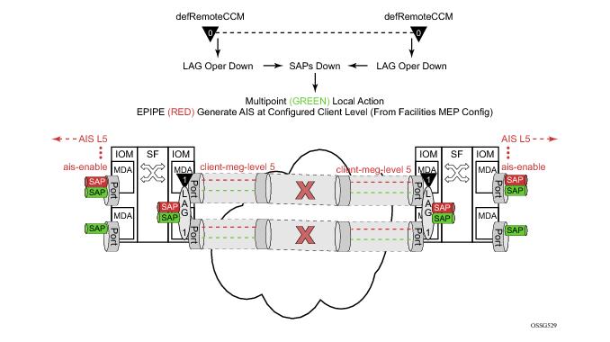
A LAG facility MEP must not be configured with facility-fault when it is applied to an MC-LAG. Traffic will black hole when the LAG Facility MEP enters a defect state. The LAG enters an operational
down state but the MC-LAG does not switch over to the peer node. This restriction does not include Tunnel Facility MEPs which are applied to a LAG with an outer VLAN. Tunnel facility MEPs do not control the operational state of the LAG because they are outer VLAN specific.
The following illustration, Figure 35, uses a port-based MEP to validate port-to-port connectivity.
NODE1
config>eth-cfm# info
----------------------------------------------
domain 1 format none level 1
association 1 format icc-based name "FacilityLag01"
ccm-interval 1
remote-mepid 22
exit
exit
domain 10 format none level 0
association 1 format icc-based name "FacilityPort0"
ccm-interval 1
remote-mepid 2
exit
exit
----------------------------------------------
config>port# info
----------------------------------------------
ethernet
mode access
encap-type qinq
eth-cfm
mep 1 domain 10 association 1
facility-fault
ccm-enable
low-priority-defect allDef
mac-address d0:0d:1e:00:00:01
no shutdown
exit
exit
autonegotiate limited
exit
no shutdown
----------------------------------------------
config>lag# info
----------------------------------------------
mode access
encap-type qinq
eth-cfm
mep 11 domain 1 association 1
ais-enable
client-meg-level 5
exit
ccm-enable
facility-fault
low-priority-defect allDef
no shutdown
exit
exit
port 1/1/2
no shutdown
----------------------------------------------
config>service# info
----------------------------------------------
customer 1 create
description "Default customer"
exit
epipe 100 customer 1 create
sap 1/1/10:100.31 create
exit
sap lag-1:100.31 create
eth-cfm
ais-enable
exit
exit
no shutdown
exit
vpls 200 customer 1 create
stp
shutdown
exit
sap 1/1/10:200.20 create
exit
sap lag-1:200.20 create
exit
no shutdown
exit
----------------------------------------------
NODE2
config>eth-cfm# info
----------------------------------------------
domain 1 format none level 1
association 1 format icc-based name "FacilityLag01"
ccm-interval 1
remote-mepid 11
exit
exit
domain 10 format none level 0
association 1 format icc-based name "FacilityPort0"
ccm-interval 1
remote-mepid 1
exit
exit
----------------------------------------------
config>port# info
----------------------------------------------
ethernet
mode access
encap-type qinq
eth-cfm
mep 2 domain 10 association 1
facility-fault
ccm-enable
low-priority-defect allDef
mac-address d0:0d:1e:00:00:02
no shutdown
exit
exit
autonegotiate limited
exit
no shutdown
----------------------------------------------
config>lag# info
----------------------------------------------
mode access
encap-type qinq
eth-cfm
mep 22 domain 1 association 1
ais-enable
client-meg-level 5
exit
facility-fault
ccm-enable
low-priority-defect allDef
no shutdown
exit
exit
port 1/1/2
no shutdown
----------------------------------------------
config>service# info
----------------------------------------------
customer 1 create
description "Default customer"
exit
epipe 100 customer 1 create
sap 1/1/10:100.31 create
exit
sap lag-1:100.31 create
eth-cfm
ais-enable
exit
exit
no shutdown
exit
vpls 200 customer 1 create
stp
shutdown
exit
sap 1/1/10:200.20 create
exit
sap lag-1:200.20 create
exit
no shutdown
exit
----------------------------------------------
NODE1
#show port
===============================================================================
Ports on Slot 1
===============================================================================
Port Admin Link Port Cfg Oper LAG/ Port Port Port C/QS/S/XFP/
Id State State MTU MTU Bndl Mode Encp Type MDIMDX
-------------------------------------------------------------------------------
…snip..
1/1/2 Up Yes Up 1522 1522 - accs qinq xcme
…snip..
show eth-cfm mep 11 domain 1 association 1
===============================================================================
Eth-Cfm MEP Configuration Information
===============================================================================
Md-index : 1 Direction : Down
Ma-index : 1 Admin : Enabled
MepId : 11 CCM-Enable : Disabled
Port : lag-1 VLAN : 0
Description : (Not Specified)
FngState : fngDefectReported ControlMep : False
LowestDefectPri : allDef HighestDefect : defRDICCM
Defect Flags : bDefRDICCM
Mac Address : 90:f3:ff:00:01:41 ControlMep : False
CcmLtmPriority : 7
CcmTx : 4428 CcmSequenceErr : 0
Fault Propagation : disabled FacilityFault : Notify
MA-CcmInterval : 1 MA-CcmHoldTime : 0ms
Eth-1Dm Threshold : 3(sec) MD-Level : 1
Eth-Ais: : Enabled Eth-Ais Rx Ais: : No
Eth-Ais Tx Priorit*: 7 Eth-Ais Rx Interv*: 1
Eth-Ais Tx Interva*: 1 Eth-Ais Tx Counte*: 1085
Eth-Ais Tx Levels : 5
Eth-Tst: : Disabled
…snip…
# show service sap-using eth-cfm facility
===============================================================================
Service ETH-CFM Facility Information
===============================================================================
SapId SvcId SAP AIS SAP Tunnel SVC Tunnel
Fault Fault
-------------------------------------------------------------------------------
lag-1:100.31 100 Enabled Accept Ignore
lag-1:200.20 200 Disabled Accept Ignore
-------------------------------------------------------------------------------
No. of Facility SAPs: 2
===============================================================================
# show eth-cfm cfm-stack-table facility
===============================================================================
CFM Stack Table Defect Legend:
R = Rdi, M = MacStatus, C = RemoteCCM, E = ErrorCCM, X = XconCCM, A = AisRx
===============================================================================
CFM Facility Port Stack Table
===============================================================================
Port Tunnel Lvl Dir Md-index Ma-index MepId Mac-address Defect
-------------------------------------------------------------------------------
1/1/2 0 0 Down 10 1 1 d0:0d:1e:00:00:01 ------
===============================================================================
===============================================================================
CFM Facility LAG Stack Table
===============================================================================
Lag Tunnel Lvl Dir Md-index Ma-index MepId Mac-address Defect
-------------------------------------------------------------------------------
lag-1 0 1 Down 1 1 11 90:f3:ff:00:01:41 R-----
===============================================================================
A:Dut-C# show service id 1 sap 1/1/1 base
===============================================================================
Service Access Points(SAP)
===============================================================================
Service Id : 1
SAP : 1/1/1 Encap : null
Description : (Not Specified)
Admin State : Up Oper State : Up
Flags : None
Multi Svc Site : None
Last Status Change : 02/24/2012 11:37:55
Last Mgmt Change : 02/24/2012 11:31:32
Sub Type : regular
Dot1Q Ethertype : 0x8100 QinQ Ethertype : 0x8100
Split Horizon Group: (Not Specified)
Max Nbr of MAC Addr: No Limit Total MAC Addr : 0
Learned MAC Addr : 0 Static MAC Addr : 0
Admin MTU : 1514 Oper MTU : 1514
Ingr IP Fltr-Id : n/a Egr IP Fltr-Id : n/a
Ingr Mac Fltr-Id : n/a Egr Mac Fltr-Id : n/a
Ingr IPv6 Fltr-Id : n/a Egr IPv6 Fltr-Id : n/a
tod-suite : None qinq-pbit-marking : both
Ing Agg Rate Limit : max Egr Agg Rate Limit: max
Q Frame-Based Acct : Disabled
ARP Reply Agent : Disabled Host Conn Verify : Disabled
Mac Learning : Enabled Discard Unkwn Srce: Disabled
Mac Aging : Enabled Mac Pinning : Disabled
BPDU Translation : Disabled
L2PT Termination : Disabled
Vlan-translation : None
Acct. Pol : None Collect Stats : Disabled
Anti Spoofing : None Dynamic Hosts : Enabled
Avl Static Hosts : 0 Tot Static Hosts : 0
Calling-Station-Id : n/a
Application Profile: None
Oper Group : (none) Monitor Oper Grp : (none)
Restr MacProt Src : Disabled Restr MacUnpr Dst : Disabled
Auto Learn Mac Prot: Disabled RestProtSrcMacAct : Disable
Time to RetryReset : never Retries Left : 3
Mac Move : Blockable Blockable Level : Tertiary
Egr MCast Grp :
Auth Policy : None
-------------------------------------------------------------------------------
ETH-CFM SAP specifics
-------------------------------------------------------------------------------
Tunnel Faults : n/a AIS : Disabled
MC Prop-Hold-Timer : n/a V-MEP Filtering : Disabled
===============================================================================
A:Dut-C#
Epipe services support the ais-enable configuration option on the SAP. Enabling this option generates AIS in the event the tunnel MEP has entered a fault state as a result of ETH-CC failure, similar to other facility MEPs. However, since the individual SAPs configured within the different services are not directly affected by the tunnel MEP, an additional configuration is necessary to perform local SAP transitions, in the case of VPLS, EIS and VPRN services and OAM mapping functions for Epipe services.
The tunnel-fault service-level command configured on an Epipe allows SAP flags to be set and fault propagation and OAM mapping functions between technology. The operational state of the SAP remains
up. The operator needs to determine if the AIS generation of fault propagation is the best approach in their specific network. It is possible to configure both
ais-enable and
tunnel-fault accept within the Epipe service. However, this may generate multiple ETH-CFM packets, or multiple actions as a result of a single failure.
The tunnel-fault accept service level option is also available under Epipe, VPLS and IES services hierarchy level within the CLI. This allows for a tunnel fault to share fate with these service SAPs. For the non-Epipe services, the SAP enters an operationally
down state, and normal processing occurs as a result of the SAP transition. In order to generate any ETH-CC based fault propagation,
suspend-cmm or
use-int-stat-tlv, this requires service-based MEPs that are actively running CCM with a peer.
The tunnel-fault configuration options occur in two levels of the CLI hierarchy: service level and SAP level. Both of the levels within a service and within the SAP (whose underlying port and outer tag has a tunnel MEP) must be set to accept, in order to have the function enabled. By default the
tunnel-fault is set to ignore at the service level and accept at the SAP level. This means that a single
tunnel-fault accept at the service level will enable fault operations for all SAPs in the service. The operator is free to enable and disable on specific SAPs by choosing the
ignore option under the individual SAP. The combination of
accept at the service level and
ignore at the SAP level prevents that specific SAP from recognizing fault. AIS generation for Epipe services is not controlled by the
tunnel-fault configuration options.
Specific to tunnel MEPs, reception of AIS on the tunnel MEP causes AIS to be cut through to all Epipe services that have the ais-enabled command configured under the SAP. During a fault condition, it is important that the AIS configuration under the tunnel MEP not be modified. This causes increased network element CPU processing requirements and in scaled environments transitioning this command during a heavily loaded fault condition, where highly scaled SAPs are linked to the fate of the tunnel MEP, may cause the system to spend more than normal processing time to be spent dealing with this artificially induced clear and fault situation. It is not expected that operators perform these types of tasks in production networks. Reception of AIS will not trigger a fault condition or AIS to be cut through when sub second CCM intervals have been configured on the Tunnel MEP.
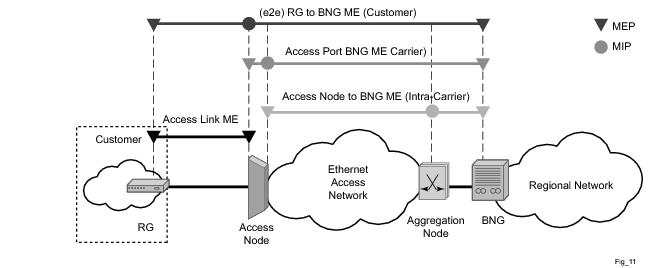
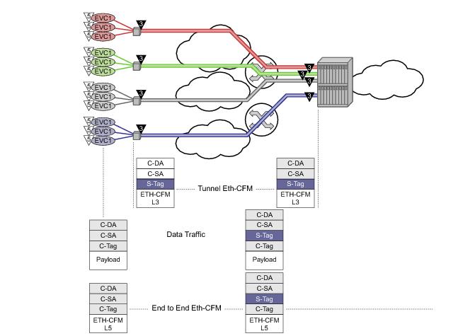
Tunnel MEPs are meant to propagate fault from one segment to the other for Epipe services. Figure 36 shows how individual Epipes have SAPs connecting to a legacy network. A MEP is configured at the tunnel level and peers with a single remote peer MEP.
Individual services can be monitored end-to-end by placing a MEP on the service endpoint at the CPE, denoted by the MEP at level 5 on the individual EVC (customer levels 5-7). The Network Interface Demarcation (NID) typically places a single tag, outer or only, on the customer traffic. This is cross connected to the proper connection in the access network and eventually arrive on the Ethernet Aggregation Switch. The connection between the legacy or access network and the aggregation switch must be either a LAG bundle or MC-LAG in order for tunnel MEPs to be configured.
A SAP is needed in order for the Tunnel MEP to extract the tunnel MEP ETH-CFM packets at the appropriate level. No SAP record is created by default. A service must already exist that includes a SAP in the form lag-id:vid.* or
lag-id:vid.0 where the vid matches the outer VLAN in which the tunnel is to monitor. Since the ETH-CFM traffic arrives at the Ethernet aggregation node as a single outer tag with no inner tag, the operator may want to consider the ability to configure the
lag-id:vid.0 to accept untagged only frames with the matching outer tag and no inner tag. The global command
configure>system->ethernet>new-qinq-untagged-sap is available to enable this functionality. By default both the
vid.* and
vid.0 accepts all packets that match the outer vid and any inner vid. If no SAP record exists for this VLAN, one must be created manually. Manually creating this SAP requires a service context. Alcatel-Lucent recommends that an Epipe service be configured with this single SAP, preventing any flooding of packets. It is possible to use a VPLS instance and combine many tunnel SAP records into a single service instance. However, configuration errors may result in leakage because of the multipoint nature of a VPLS service. Regardless of the service type chosen, it should be in a
shutdown state. Also, normal ETH-CFM rules apply. ETH-CFM packets arriving on the SAP passes all ETH-CFM packets at and below the tunnel MEP to the ETH-CFM application for processing.
The goal of a Tunnel MEP is to validate an attachment circuit and relate the state to services that share the same LAG and outer VLAN to other services across the network. Tunnel MEPs are not intended for propagating fault between two endpoints that share the same LAG and outer VLAN. For this reason, locally switched circuits that share the same LAG and the same outer tag must not use the ais-enable function under those SAPs. As an example, lag-1 may have two SAPs associated with it: lag-1:1.1 and lag-1:1.2. These two SAP represent two different endpoints on the same LAG using the same outer VLAN. In this case, if the
ais-enable is configured under both SAPs, AIS functionality does not work properly. Normal fault propagation could be used in this case instead. Since the tunnel MEP is validating the common physical path and these two MEPs share the common physical path, there is no reason to propagate fault. Service-based MEPs could be configured on the endpoints in order to validate the connectivity between the two endpoints when this type of model is deployed. However, two SAPs that are connected to different LAGs is a supported configuration. An example of this would be lag-1:1.1 and lag-2:1.1.
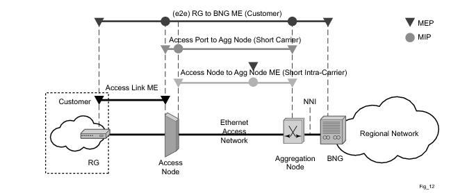
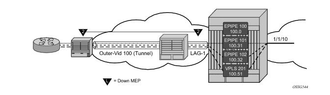
The following illustration, Figure 37, shows how fate can be shared between the Tunnel MEP and the services configured on the same LAG and outer VLAN.
AGGREGATION NODE
config>eth-cfm# info
----------------------------------------------
domain 2 format none level 2
association 1 format icc-based name "FacilityTun01"
ccm-interval 1
remote-mepid 101
exit
exit
----------------------------------------------
config>lag# info
----------------------------------------------
mode access
encap-type qinq
eth-cfm
mep 100 domain 2 association 1 vlan 100
description "Tunnel Facility MEP - Do NOT Delete"
ais-enable
client-meg-level 5
exit
facility-fault
ccm-enable
low-priority-defect allDef
no shutdown
exit
exit
port 1/1/2
no shutdown
----------------------------------------------
config>service# info
----------------------------------------------
customer 1 create
description "Default customer"
exit
epipe 100 customer 1 create
shutdown
description "Tunnel Extraction Service"
sap lag-1:100.0 create
exit
exit
epipe 101 customer 1 create
description "Customer Service 100.31"
sap 1/1/10:100.31 create
exit
sap lag-1:100.31 create
eth-cfm
ais-enable
exit
exit
no shutdown
exit
epipe 102 customer 1 create
description "Customer Service 100.32"
eth-cfm
tunnel-fault accept
exit
sap 1/1/10:100.32 create
exit
sap lag-1:100.32 create
exit
no shutdown
exit
vpls 201 customer 1 create
description "Customer Service 100.51"
stp
shutdown
exit
eth-cfm
tunnel-fault accept
exit
sap 1/1/10:100.51 create
exit
sap lag-1:100.51 create
exit
no shutdown
exit
----------------------------------------------
# show eth-cfm mep 100 domain 2 association 1
===============================================================================
Eth-Cfm MEP Configuration Information
===============================================================================
Md-index : 2 Direction : Down
Ma-index : 1 Admin : Enabled
MepId : 100 CCM-Enable : Enabled
Port : lag-1 VLAN : 100
Description : Tunnel Facility MEP - Do NOT Delete
FngState : fngReset ControlMep : False
LowestDefectPri : allDef HighestDefect : none
Defect Flags : None
Mac Address : 90:f3:ff:00:01:41 ControlMep : False
CcmLtmPriority : 7
CcmTx : 3958 CcmSequenceErr : 0
Fault Propagation : disabled FacilityFault : Notify
MA-CcmInterval : 1 MA-CcmHoldTime : 0ms
Eth-1Dm Threshold : 3(sec) MD-Level : 2
Eth-Ais: : Enabled Eth-Ais Rx Ais: : No
Eth-Ais Tx Priorit*: 7 Eth-Ais Rx Interv*: 1
Eth-Ais Tx Interva*: 1 Eth-Ais Tx Counte*: 175
Eth-Ais Tx Levels : 5
Eth-Tst: : Disabled
Redundancy:
MC-LAG State : n/a
CcmLastFailure Frame:
None
XconCcmFailure Frame:
None
===============================================================================
# show eth-cfm cfm-stack-table facility all-tunnel-meps
===============================================================================
CFM Stack Table Defect Legend:
R = Rdi, M = MacStatus, C = RemoteCCM, E = ErrorCCM, X = XconCCM, A = AisRx
===============================================================================
CFM Facility LAG Stack Table
===============================================================================
Lag Tunnel Lvl Dir Md-index Ma-index MepId Mac-address Defect
-------------------------------------------------------------------------------
lag-1 100 2 Down 2 1 100 90:f3:ff:00:01:41 ------
===============================================================================
# show service sap-using eth-cfm facility
===============================================================================
Service ETH-CFM Facility Information
===============================================================================
SapId SvcId SAP AIS SAP Tunnel SVC Tunnel
Fault Fault
-------------------------------------------------------------------------------
lag-1:100.0 100 Disabled Accept Ignore
lag-1:100.31 101 Enabled Accept Ignore
lag-1:100.32 102 Disabled Accept Accept
lag-1:100.51 201 Disabled Accept Accept
-------------------------------------------------------------------------------
No. of Facility SAPs: 4
===============================================================================
When the tunnel MEP enters a fault state
• Epipe 101 will start to generate AIS out the mate sap
• Epipe 102 SAP flag will be set
• VPLS 201 SAP will go down
Output from one of the nodes is included below. Since both will react in the same manner output from both nodes is not required.
AGGREGATION NODE
# show eth-cfm cfm-stack-table facility all-tunnel-meps
===============================================================================
CFM Stack Table Defect Legend:
R = Rdi, M = MacStatus, C = RemoteCCM, E = ErrorCCM, X = XconCCM, A = AisRx
===============================================================================
CFM Facility LAG Stack Table
===============================================================================
Lag Tunnel Lvl Dir Md-index Ma-index MepId Mac-address Defect
-------------------------------------------------------------------------------
lag-1 100 2 Down 2 1 100 90:f3:ff:00:01:41 --C---
===============================================================================
# show service sap-using eth-cfm facility tunnel 100
===============================================================================
Service ETH-CFM Facility Information
===============================================================================
SapId SvcId SAP AIS SAP Tunnel SVC Tunnel
Fault Fault
-------------------------------------------------------------------------------
lag-1:100.0 100 Disabled Accept Ignore
lag-1:100.31 101 Enabled Accept Ignore
lag-1:100.32 102 Disabled Accept Accept
lag-1:100.51 201 Disabled Accept Accept
-------------------------------------------------------------------------------
No. of Facility SAPs: 4
===============================================================================
# show eth-cfm mep 100 domain 2 association 1
===============================================================================
Eth-Cfm MEP Configuration Information
===============================================================================
Md-index : 2 Direction : Down
Ma-index : 1 Admin : Enabled
MepId : 100 CCM-Enable : Enabled
Port : lag-1 VLAN : 100
Description : Tunnel Facility MEP - Do NOT Delete
FngState : fngDefectReported ControlMep : False
LowestDefectPri : allDef HighestDefect : defRemoteCCM
Defect Flags : bDefRemoteCCM
Mac Address : 90:f3:ff:00:01:41 ControlMep : False
CcmLtmPriority : 7
CcmTx : 4211 CcmSequenceErr : 0
Fault Propagation : disabled FacilityFault : Notify
MA-CcmInterval : 1 MA-CcmHoldTime : 0ms
Eth-1Dm Threshold : 3(sec) MD-Level : 2
Eth-Ais: : Enabled Eth-Ais Rx Ais: : No
Eth-Ais Tx Priorit*: 7 Eth-Ais Rx Interv*: 1
Eth-Ais Tx Interva*: 1 Eth-Ais Tx Counte*: 215
Eth-Ais Tx Levels : 5
Eth-Tst: : Disabled
Redundancy:
MC-LAG State : n/a
CcmLastFailure Frame:
None
XconCcmFailure Frame:
None
===============================================================================
show service id 101 base
===============================================================================
Service Basic Information
===============================================================================
Service Id : 101 Vpn Id : 0
Service Type : Epipe
Name : (Not Specified)
Description : Customer Service 100.31
Customer Id : 1
Last Status Change: 02/04/2010 15:53:12
Last Mgmt Change : 02/04/2010 16:31:00
Admin State : Up Oper State : Up
MTU : 1514
Vc Switching : False
SAP Count : 2 SDP Bind Count : 0
Per Svc Hashing : Disabled
Force QTag Fwd : Disabled
-------------------------------------------------------------------------------
Service Access & Destination Points
-------------------------------------------------------------------------------
Identifier Type AdmMTU OprMTU Adm Opr
-------------------------------------------------------------------------------
sap:1/1/10:100.31 qinq 1522 1522 Up Up
sap:lag-1:100.31 qinq 1522 1522 Up Up
===============================================================================
# show service id 102 base
===============================================================================
Service Basic Information
===============================================================================
Service Id : 102 Vpn Id : 0
Service Type : Epipe
Name : (Not Specified)
Description : Customer Service 100.32
Customer Id : 1
Last Status Change: 02/04/2010 15:45:07
Last Mgmt Change : 02/04/2010 16:30:43
Admin State : Up Oper State : Up
MTU : 1514
Vc Switching : False
SAP Count : 2 SDP Bind Count : 0
Per Svc Hashing : Disabled
Force QTag Fwd : Disabled
-------------------------------------------------------------------------------
Service Access & Destination Points
-------------------------------------------------------------------------------
Identifier Type AdmMTU OprMTU Adm Opr
-------------------------------------------------------------------------------
sap:1/1/10:100.32 qinq 1522 1522 Up Up
sap:lag-1:100.32 qinq 1522 1522 Up Up
===============================================================================
# show service id 102 sap lag-1:100.32
===============================================================================
Service Access Points(SAP)
===============================================================================
Service Id : 102
SAP : lag-1:100.32 Encap : qinq
QinQ Dot1p : Default
Description : (Not Specified)
Admin State : Up Oper State : Up
Flags : OamTunnelMEPFault
Multi Svc Site : None
Last Status Change : 02/04/2010 15:45:07
Last Mgmt Change : 02/04/2010 15:44:26
-------------------------------------------------------------------------------
ETH-CFM SAP specifics
-------------------------------------------------------------------------------
Tunnel Faults : accept AIS : Disabled
MC Prop-Hold-Timer : n/a
===============================================================================
# show service id 201 base
===============================================================================
Service Basic Information
===============================================================================
Service Id : 201 Vpn Id : 0
Service Type : VPLS
Name : (Not Specified)
Description : Customer Service 100.51
Customer Id : 1
Last Status Change: 02/04/2010 15:46:03
Last Mgmt Change : 02/04/2010 16:30:29
Admin State : Up Oper State : Up
MTU : 1514 Def. Mesh VC Id : 201
SAP Count : 2 SDP Bind Count : 0
Snd Flush on Fail : Disabled Host Conn Verify : Disabled
Propagate MacFlush: Disabled Per Svc Hashing : Disabled
Allow IP Intf Bind: Disabled
Def. Gateway IP : None
Def. Gateway MAC : None
Temp Flood Time : Disabled Temp Flood : Inactive
Temp Flood Chg Cnt: 0
-------------------------------------------------------------------------------
Service Access & Destination Points
-------------------------------------------------------------------------------
Identifier Type AdmMTU OprMTU Adm Opr
-------------------------------------------------------------------------------
sap:1/1/10:100.51 qinq 1522 1522 Up Up
sap:lag-1:100.51 qinq 1522 1522 Up Down
===============================================================================
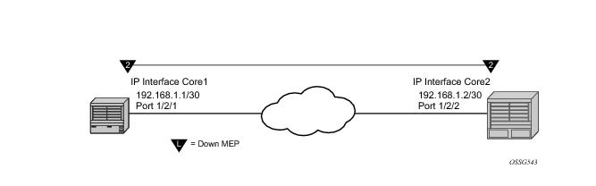
The following illustration, Figure 38, shows how a Router Facility MEP can be configured on a routed interface in the base router instance.
NODE1
config>port# info
----------------------------------------------
ethernet
exit
no shutdown
----------------------------------------------
config>eth-cfm# info
----------------------------------------------
domain 2 format none level 2
association 2 format icc-based name "FacilityRtr01"
exit
exit
----------------------------------------------
config>router# info
----------------------------------------------
#--------------------------------------------------
echo "IP Configuration"
#--------------------------------------------------
interface "Core1"
address 192.168.1.1/30
port 1/2/1
eth-cfm
mep 1 domain 2 association 2
mac-address d0:0d:1e:00:00:01
no shutdown
exit
exit
exit
interface "system"
exit
----------------------------------------------
# show eth-cfm cfm-stack-table facility all-router-interfaces
===============================================================================
CFM Stack Table Defect Legend:
R = Rdi, M = MacStatus, C = RemoteCCM, E = ErrorCCM, X = XconCCM, A = AisRx
===============================================================================
CFM Facility Interface Stack Table
===============================================================================
Interface Lvl Dir Md-index Ma-index MepId Mac-address Defect
-------------------------------------------------------------------------------
Core1 2 Down 2 2 1 d0:0d:1e:00:00:01 ------
===============================================================================
# oam eth-cfm loopback d0:0d:1e:00:00:02 mep 1 domain 2 association 2
send-count 5
Eth-Cfm Loopback Test Initiated: Mac-Address: d0:0d:1e:00:00:02, out service: 0
Sent 5 packets, received 5 packets [0 out-of-order, 0 Bad Msdu]
# oam eth-cfm linktrace d0:0d:1e:00:00:02 mep 1 domain 2 association
2
Index Ingress Mac Egress Mac Relay Action
----- -------------------- -------------------- ---------- ----------
1 D0:0D:1E:00:00:02 00:00:00:00:00:00 n/a terminate
----- -------------------- -------------------- ---------- ----------
No more responses received in the last 6 seconds.
# oam eth-cfm two-way-delay-test d0:0d:1e:00:00:02 mep 1 domain 2 association 2
Two-Way-Delay-Test Response:
Delay 1130 microseconds Variation 63 microseconds
# oam eth-cfm two-way-delay-test d0:0d:1e:00:00:02 mep 1 domain 2 association 2
Two-Way-Delay-Test Response:
Delay 1218 microseconds Variation 88 microseconds
NODE2
config>port# info
----------------------------------------------
ethernet
exit
no shutdown
----------------------------------------------
config>eth-cfm# info
----------------------------------------------
domain 2 format none level 2
association 2 format icc-based name "FacilityRtr01"
exit
exit
----------------------------------------------
config>router# info
----------------------------------------------
#--------------------------------------------------
echo "IP Configuration"
#--------------------------------------------------
interface "Core2"
address 192.168.1.2/30
port 1/2/2
eth-cfm
mep 2 domain 2 association 2
mac-address d0:0d:1e:00:00:02
no shutdown
exit
exit
exit
interface "system"
exit
----------------------------------------------
Table 4 provides an overview of Facility MEP support.
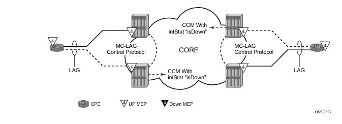
ETH-CFM MPs track the SAPs, bindings and facility independently. Therefore, when an MP is configured on a SAP which is not operationally up because of MC-LAG ETH-CFM defect, conditions are raised for what could be considered normal conditions.
Figure 39 shows the default behavior for a point-to-point service without regard for MC-LAG. In the case below, the two up MEPs operating at level 4 on the affected SAPs set the
Interface-Status-TLV bit in the ETH-CC header to represent the
isDown condition, assuming ETH-CC is executing between the peer MEPs. This is the correct action based on the ETH-CFM perspective, SAPs are operationally
down.
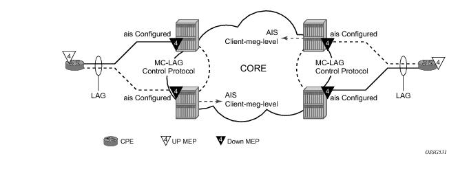
A similar condition exists if down MEPs are configured on the SAPs that are operationally down.
Figure 40 shows how the same service configured with down MEPs would generate AIS, if enabled, toward the remote client at the configured client-meg-level, in the reverse direction of the MEP. This is also the proper behavior from the perspective ETH-CFM.
ETH-CFM will register a fault propagation delay timer equal to propagate-hold-time under the
config>eth-cfm>redundancy>mc-lag hierarchy (default of 1s) to delay notification of an event that may be a result of MC-LAG failover. This allows the system time to coordinate events and triggers that together represent the MC-LAG transition from active to standby.
A fixed timer value of 1s will delay an UP MEP from announcing a SAP down condition through CCM Interface-Status-TLV bits, isDown. ETH-CFM maintains a status of last sent to the UP MEPs peer. When the SAP transitions either to UP or DOWN that fault will be held for the fixed 1s interval and the last Interface-Status-TLV bits will set based on the previous transmission. If the condition, different from the previous sent, still exists at the end of the 1s fixed timer and when the next CCM interval expires, the representative value of the SAP will be sent in the Interface-Status-TLV. These two timers help to smooth out network transitions at the cost of propagation and clearing of faults.
Administrative functions, like admin down, are special cases. When the administrative state changes from
up to
down, the timer is bypassed and communication from ETH-CFM is immediate.
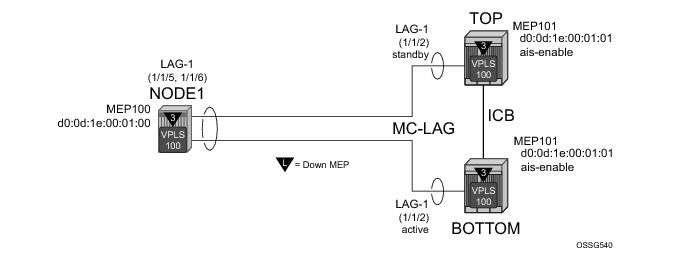
NODE1
config>port# info (both ports)
----------------------------------------------
ethernet
mode access
encap-type qinq
autonegotiate limited
exit
no shutdown
----------------------------------------------
config>lag# info
----------------------------------------------
mode access
encap-type qinq
access
adapt-qos link
exit
port 1/1/5
port 1/1/6
lacp active administrative-key 32768
hold-time down 10
no shutdown
----------------------------------------------
config>eth-cfm# info
----------------------------------------------
domain 3 format none level 3
association 1 format icc-based name "03-0000000100"
bridge-identifier 100
exit
ccm-interval 1
remote-mepid 101
exit
exit
----------------------------------------------
config>service>vpls# info
----------------------------------------------
stp
shutdown
exit
sap 1/1/3:100.100 create
exit
sap lag-1:100.100 create
eth-cfm
mep 100 domain 3 association 1 direction down
ccm-enable
mac-address d0:0d:1e:00:01:00
no shutdown
exit
exit
exit
no shutdown
----------------------------------------------
TOP (MC-LAG Standby)
config>port# info
----------------------------------------------
ethernet
mode access
encap-type qinq
autonegotiate limited
exit
no shutdown
----------------------------------------------
config>lag# info
----------------------------------------------
mode access
encap-type qinq
access
adapt-qos link
exit
port 1/1/2
lacp active administrative-key 32768
no shutdown
----------------------------------------------
config>router# info
----------------------------------------------
#--------------------------------------------------
echo "IP Configuration"
#--------------------------------------------------
interface "Core2"
address 192.168.1.2/30
port 1/2/2
exit
interface "system"
exit
----------------------------------------------
config>redundancy# info
----------------------------------------------
multi-chassis
peer 192.168.1.1 create
source-address 192.168.1.2
mc-lag
lag 1 lacp-key 1 system-id 00:00:00:00:00:01 system-priority
100
no shutdown
exit
no shutdown
exit
exit
synchronize boot-env
----------------------------------------------
config>eth-cfm# info
----------------------------------------------
domain 3 format none level 3
association 1 format icc-based name "03-0000000100"
bridge-identifier 100
exit
ccm-interval 1
remote-mepid 100
exit
exit
redundancy
mc-lag
standby-mep-shutdown
exit
exit
----------------------------------------------
config>service>vpls# info
----------------------------------------------
stp
shutdown
exit
sap lag-1:100.100 create
eth-cfm
mep 101 domain 3 association 1 direction down
exit
ccm-enable
mac-address d0:0d:1e:00:01:01
no shutdown
exit
exit
exit
no shutdown
----------------------------------------------
# show lag 1
===============================================================================
Lag Data
===============================================================================
Lag-id Adm Opr Port-Threshold Up-Link-Count MC Act/Stdby
-------------------------------------------------------------------------------
1 up down 0 0 standby
===============================================================================
# show port
===============================================================================
Ports on Slot 1
===============================================================================
Port Admin Link Port Cfg Oper LAG/ Port Port Port C/QS/S/XFP/
Id State State MTU MTU Bndl Mode Encp Type MDIMDX
-------------------------------------------------------------------------------
… snip …
1/1/2 Up Yes Link Up 1522 1522 1 accs qinq xcme
…snip…
==========================================================================
BOT (MC-LAG Active)
config>port# info
----------------------------------------------
ethernet
mode access
encap-type qinq
autonegotiate limited
exit
no shutdown
----------------------------------------------
config>lag# info
----------------------------------------------
mode access
encap-type qinq
access
adapt-qos link
exit
port 1/1/2
lacp active administrative-key 32768
no shutdown
----------------------------------------------
config>router# info
----------------------------------------------
#--------------------------------------------------
echo "IP Configuration"
#--------------------------------------------------
interface "Core1"
address 192.168.1.1/30
port 1/2/1
exit
interface "system"
exit
----------------------------------------------
config>redundancy# info
----------------------------------------------
multi-chassis
peer 192.168.1.2 create
source-address 192.168.1.1
mc-lag
lag 1 lacp-key 1 system-id 00:00:00:00:00:01 system-priority
100
no shutdown
exit
no shutdown
exit
exit
synchronize boot-env
----------------------------------------------
config>eth-cfm# info
----------------------------------------------
domain 3 format none level 3
association 1 format icc-based name "03-0000000100"
bridge-identifier 100
exit
ccm-interval 1
remote-mepid 100
exit
exit
redundancy
mc-lag
standby-mep-shutdown
exit
exit
----------------------------------------------
config>service>vpls# info
----------------------------------------------
stp
shutdown
exit
sap lag-1:100.100 create
eth-cfm
mep 101 domain 3 association 1 direction down
exit
ccm-enable
mac-address d0:0d:1e:00:01:01
no shutdown
exit
exit
exit
no shutdown
----------------------------------------------
# show lag 1
===============================================================================
Lag Data
===============================================================================
Lag-id Adm Opr Port-Threshold Up-Link-Count MC Act/Stdby
-------------------------------------------------------------------------------
1 up up 0 1 active
===============================================================================
# show port
===============================================================================
Ports on Slot 1
===============================================================================
Port Admin Link Port Cfg Oper LAG/ Port Port Port C/QS/S/XFP/
Id State State MTU MTU Bndl Mode Encp Type MDIMDX
-------------------------------------------------------------------------------
…snip…
1/1/2 Up Yes Up 1522 1522 1 accs qinq xcme
…snip…
===============================================================================
When the ccm-hold-timer down delay-down option is configured the following calculation is used to determine the remote peer time out (3.5 times the CCM-Interval + ccm-hold-timer delay-down).
Note1: Ethernet-Tunnels and Ethernet-Rings are not configurable under all service types. Any service restrictions for MEP direction or MIP support will override the generic capability of the Ethernet-Tunnel or Ethernet-Ring MPs. Check the applicable user guide for applicability.
An optional vmep-filter provides a coarse means of silently dropping all ETH-CFM packets that would normally be redirected to the CPU following egress processing. These includes any ETH-CFM level equal to or lower than the vMEP and any level equal to and lower than any other Management Points on the same SAP or SDP binding that includes the
vmep-filter. MIPs will automatically be deleted when they coexist on the same SAP or spoke-sdp as the
vmep-filter. Since DOWN MEPs are ingress processed they are supported in combination with a vMEP and operate normally regardless of any
vmep-filter. Domain nesting rules must be adhered to.
config>service# vpls 100 customer 1 create
config>service>vpls$ info
----------------------------------------------
stp
shutdown
exit
eth-cfm
mep 100 domain 3 association 1
mac-address d0:0d:1e:00:01:11
ccm-enable
no shutdown
exit
exit
no shutdown
----------------------------------------------
Note: To use any Y.1731 specific function, the domain must be configured with a domain format of “none”. This includes the MEPs that are created as part of the G.8031 and G.8032 protection scheme. That is because they use ETH-APS as defined in the ITU-T Y.1731 recommendation and are not part of the IEEE 802.1ag specification.
To access a specific customer account, you must specify the customer ID.
To display a list of customer IDs, use the show service customer command.
Enter the parameter (
description,
contact,
phone) and then enter the new information.
Example:
config>service# customer 27 create
config>service>customer$ description “Western Division”
config>service>customer# contact “John Dough”
config>service>customer# no phone “(650) 237-5102”
The no form of the customer command removes a customer ID and all associated information. All service references to the customer must be shut down and deleted before a customer account can be deleted.
Example:
config>service# epipe 5 customer 27 shutdown
config>service# epipe 9 customer 27 shutdown
config>service# no epipe 5
config>service# no epipe 9
config>service# no customer 27
To access a specific SDP, you must specify the SDP ID. To display a list of SDPs, use the show service sdp command. Enter the parameter, such as
description,
far-end, and
lsp, and then enter the new information.
NOTE: Once created, you cannot modify the SDP encapsulation type.
Example:
config>service# sdp 79
config>service>sdp# description “Path-to-107”
config>service>sdp# shutdown
config>service>sdp# far-end “10.10.10.107”
config>service>sdp# path-mtu 1503
config>service>sdp# no shutdown
The no form of the sdp command removes an SDP ID and all associated information. Before an SDP can be deleted, the SDP must be shutdown and removed (unbound) from all customer services where it is applied.
Example:
config>service# epipe 5 spoke-sdp 79:5
config>service>epipe>sdp# shutdown
config>service>epipe>sdp# exit
config>service>epipe# exit
config>service# no sdp 79


 .
.