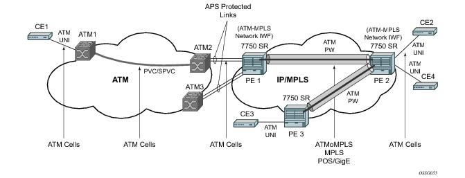
ATM VLLs (Apipe) provide a point-to-point ATM service between users connected to 7750 SR nodes on an IP/MPLS network. Users are either directly connected to a 7750 PE or through an ATM access network. In both cases, an ATM PVC (for example, a virtual channel (VC) or a virtual path (VP)) is configured on the 7750 PE. This feature supports local cross-connecting when users are attached to the same 7750 PE node. VPI/VCI translation is supported in the ATM VLL.
PE1, PE2, and PE3 receive standard UNI/NNI cells on the ATM Service Access Point (SAP) that are then encapsulated into a pseudowire packet using the N:1 cell mode encapsulation or AAL5 SDU mode encapsulation according to RFC 4717, Encapsulation Methods for Transport of ATM Over MPLS Networks. When using N:1 cell mode encapsulation, cell concatenation into a pseudowire packet is supported. In this application, the setup of both VC and VP level connections are supported.
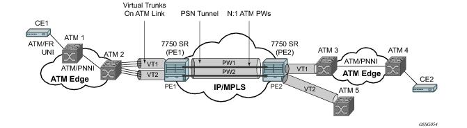
ATM virtual trunk (VT) implements a transparent trunking of user and control traffic between two ATM switches over an ATM pseudowire. Figure 31 depicts ATM 2 and ATM 3 switches that appear as if they are directly connected over an ATM link. Control traffic includes PNNI signaling and routing traffic.
The virtual trunk (VT) SAP on a 7750 PE is identified by a tuple (port, VPI-range) meaning that all cells arriving on the specified port within the specified VPI range are fed into a single ATM pseudowire for transport across the IP/MPLS network. Note that a user can configure the whole ATM port as a VT and does not need to specify a VPI range. No VPI/VCI translation is performed on ingress or egress. Cell order is maintained within a VT. Note that, as a special case, the two ATM ports could be on the same PE node.
The ATM pseudowire is initiated using Targeted LDP (TLDP) signaling (defined in RFC 4447, Pseudowire Setup and Maintenance using LDP). In this application, there is no ATM signaling on the 7750 gateway nodes since both endpoints of the MPLS network are configured by the network operator. ATM signaling between the ATM nodes is passed transparently over the VT (along with user traffic) from one ATM port on a 7750 PE to another ATM port on a remote (or the same) 7750 SR PE.
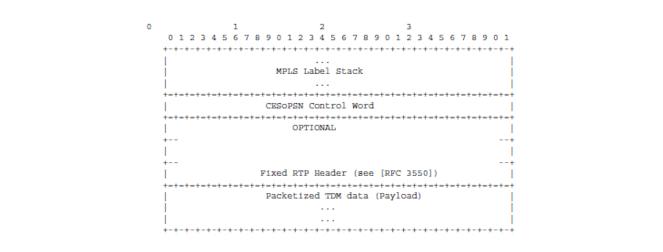
Two modes of circuit emulation are supported, unstructured and structured. Unstructured mode is supported for DS1 and E1 channels per RFC 4553, Structure-Agnostic Time Division Multiplexing (TDM) over Packet (SAToP). Structured mode is supported for n*64 kbps circuits as per RFC 5086,
Structure-Aware Time Division Multiplexed (TDM) Circuit Emulation Service over Packet Switched Network (CESoPSN). In addition, DS1, E1 and n*64 kbps circuits are supported (per MEF8). TDM circuits are optionally encapsulated in MPLS or Ethernet as per the referenced standards in the following figures.
0 1 2 3
0 1 2 3 4 5 6 7 8 9 0 1 2 3 4 5 6 7 8 9 0 1 2 3 4 5 6 7 8 9 0 1
+-+-+-+-+-+-+-+-+-+-+-+-+-+-+-+-+-+-+-+-+-+-+-+-+-+-+-+-+-+-+-+-+
| ... |
| MPLS Label Stack |
| ... |
+=+=+=+=+=+=+=+=+=+=+=+=+=+=+=+=+=+=+=+=+=+=+=+=+=+=+=+=+=+=+=+=+
| SAToP Control Word |
+=+=+=+=+=+=+=+=+=+=+=+=+=+=+=+=+=+=+=+=+=+=+=+=+=+=+=+=+=+=+=+=+
| OPTIONAL |
+-- --+
| |
+-- --+
| Fixed RTP Header (see [RFC3550]) |
+=+=+=+=+=+=+=+=+=+=+=+=+=+=+=+=+=+=+=+=+=+=+=+=+=+=+=+=+=+=+=+=+
| Packetized TDM data (Payload) |
| ... |
| ... |
+-+-+-+-+-+-+-+-+-+-+-+-+-+-+-+-+-+-+-+-+-+-+-+-+-+-+-+-+-+-+-+-+
0 1 2 3
0 1 2 3 4 5 6 7 8 9 0 1 2 3 4 5 6 7 8 9 0 1 2 3 4 5 6 7 8 9 0 1
+-+-+-+-+-+-+-+-+-+-+-+-+-+-+-+-+-+-+-+-+-+-+-+-+-+-+-+-+-+-+-+-+
| ... |
| MPLS Label Stack |
| ... |
+=+=+=+=+=+=+=+=+=+=+=+=+=+=+=+=+=+=+=+=+=+=+=+=+=+=+=+=+=+=+=+=+
| CESoPSN Control Word |
+=+=+=+=+=+=+=+=+=+=+=+=+=+=+=+=+=+=+=+=+=+=+=+=+=+=+=+=+=+=+=+=+
| OPTIONAL |
+-- --+
| |
+-- --+
| Fixed RTP Header (see [RFC3550]) |
+=+=+=+=+=+=+=+=+=+=+=+=+=+=+=+=+=+=+=+=+=+=+=+=+=+=+=+=+=+=+=+=+
| Packetized TDM data (Payload) |
| ... |
| ... |
+-+-+-+-+-+-+-+-+-+-+-+-+-+-+-+-+-+-+-+-+-+-+-+-+-+-+-+-+-+-+-+-+
0 1 2 3
0 1 2 3 4 5 6 7 8 9 0 1 2 3 4 5 6 7 8 9 0 1 2 3 4 5 6 7 8 9 0 1
+-+-+-+-+-+-+-+-+-+-+-+-+-+-+-+-+
| Destination MAC Address
+-+-+-+-+-+-+-+-+-+-+-+-+-+-+-+-+-+-+-+-+-+-+-+-+-+-+-+-+-+-+-+-+
Destination MAC Address (cont) |
+-+-+-+-+-+-+-+-+-+-+-+-+-+-+-+-+-+-+-+-+-+-+-+-+-+-+-+-+-+-+-+-+
| Source MAC Address
+-+-+-+-+-+-+-+-+-+-+-+-+-+-+-+-+-+-+-+-+-+-+-+-+-+-+-+-+-+-+-+-+
Source MAC Address (cont) | VLAN Ethertype (opt) |
+-+-+-+-+-+-+-+-+-+-+-+-+-+-+-+-+-+-+-+-+-+-+-+-+-+-+-+-+-+-+-+-+
|VLP|C| VLAN ID (opt) | Ethertype |
+-+-+-+-+-+-+-+-+-+-+-+-+-+-+-+-+-+-+-+-+-+-+-+-+-+-+-+-+-+-+-+-+
| ECID (20 bits) | RES (set to 0x102) |
+-+-+-+-+-+-+-+-+-+-+-+-+-+-+-+-+-+-+-+-+-+-+-+-+-+-+-+-+-+-+-+-+
| RES(0)|L|R| M |FRG| Length | Sequence Number |
+-+-+-+-+-+-+-+-+-+-+-+-+-+-+-+-+-+-+-+-+-+-+-+-+-+-+-+-+-+-+-+-+
opt|RTV|P|X| CC |M| PT | RTP Sequence Number |
+-+-+-+-+-+-+-+-+-+-+-+-+-+-+-+-+-+-+-+-+-+-+-+-+-+-+-+-+-+-+-+-+
opt| Timestamp |
+-+-+-+-+-+-+-+-+-+-+-+-+-+-+-+-+-+-+-+-+-+-+-+-+-+-+-+-+-+-+-+-+
opt| SSRC identifier |
+-+-+-+-+-+-+-+-+-+-+-+-+-+-+-+-+-+-+-+-+-+-+-+-+-+-+-+-+-+-+-+-+
| |
| Adapted Payload |
| |
+-+-+-+-+-+-+-+-+-+-+-+-+-+-+-+-+-+-+-+-+-+-+-+-+-+-+-+-+-+-+-+-+
| Frame Check Sequence |
+-+-+-+-+-+-+-+-+-+-+-+-+-+-+-+-+-+-+-+-+-+-+-+-+-+-+-+-+-+-+-+-+
Figure 36 shows the format of the CESoPSN TDM payload (with and without CAS) for packets carrying trunk-specific 64 kb/s service. In CESoPSN, the payload size is dependent on the number of timeslots used.
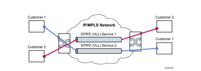
An Epipe service is a Layer 2 point-to-point service where the customer data is encapsulated and transported across a service provider’s IP, MPLS or PBB VPLS network. An Epipe service is completely transparent to the subscriber’s data and protocols. The7750 SR Epipe service does not perform any MAC learning. A local Epipe service consists of two SAPs on the same node, whereas a distributed Epipe service consists of two SAPs on different nodes. SDPs are not used in local Epipe services.
Each SAP configuration includes a specific port/channel on which service traffic enters the 7750 SR from the customer side (also called the access side). Each port is configured with an encapsulation type. If a port is configured with an IEEE 802.1Q (referred to as Dot1q) encapsulation, then a unique encapsulation value (ID) must be specified.
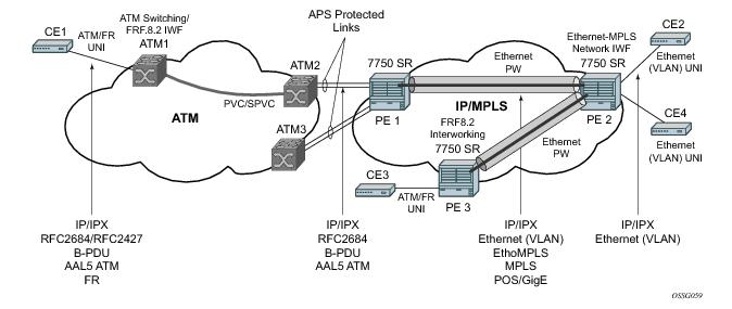
Figure 38 provides an example of an Ethernet interworking VLL. The Ethernet interworking VLL provides a point-to-point Ethernet VLL service between Frame-Relay-attached users, ATM attached users, and Ethernet-attached users across an IP/MPLS packet switched network. It effectively provides ATM and FR bridged encapsulation termination on the existing Epipe service of the 7750 SR.
Users attach over an ATM UNI with RFC 2684, Multiprotocol Encapsulation over ATM Adaptation Layer 5, tagged/untagged bridged Ethernet PDUs, a FR UNI using RFC 2427,
Multiprotocol Interconnect over Frame Relay, tagged/untagged bridged Ethernet PDUs, or an Ethernet tagged/untagged UNI interface. However, the VCI/VPI and the data-link control layer (DLCI) are the identifiers of the SAP in the case of ATM and FR respectively and the received tags are transparent to the service and are thus preserved.
To support redundant VLL access in ring configurations, the multi-chassis ring feature is applicable to VLL SAPs. A conceptual drawing of the operation is shown in Figure 39. The given CPE which is connected behind the ring node has access to both BSA through the same VLAN provisioned in all ring nodes. There are two SAPs (with the same VLAN) provisioned on both nodes.
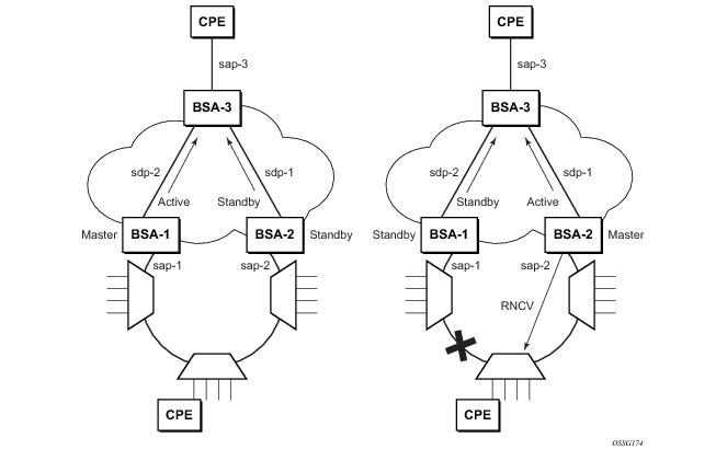
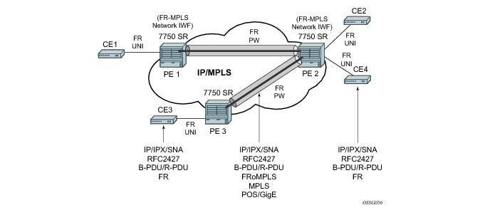
Figure 40 depicts an application of a Frame Relay VLL. The Frame Relay VLL (Fpipe) provides a point-to-point Frame Relay service between users connected to 7750 nodes on the IP/MPLS network. Users are connected to the 7750 PE nodes using Frame Relay PVCs. PE1, PE2, and PE3 receive a standard Q.922 Core frame on the Frame Relay SAP and encapsulate it into a pseudowire packet according to the 1-to-1 Frame Relay encapsulation mode in RFC 4619,
Encapsulation Methods for Transport of Frame Relay Over MPLS Networks. The 7750 Frame Relay VLL feature supports local cross-connecting when the users are attached to the same 7750 PE node.
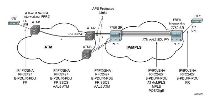
Figure 41 provides an example of a point-to-point Frame Relay service between users where one user is connected to an existing ATM network, the other to a 7750 PE node on an IP/MPLS network.
This VLL is realized using an ATM AAL5 SDU pseudowire between the 7750 SR PE nodes. It is configured by adding a FR SAP to an Apipe service using vc-type atm-sdu. The 7750 SR PE2 node performs an FRF.5 interworking function to interwork the ingress and egress data paths in addition to the operations required in an FR and an ATM VLL.
Traffic management of Frame Relay VLLs is achieved through the application of ingress and egress QoS policies to SAPs like other Frame Relay SAPs. No queuing occurs on the MDA; all queuing, policing and shaping occurs on the IOM and, as a result, traffic management is forwarding-class-aware. Forwarding classes may be determined by inspecting the DSCP marking of contained IP packets (for example) and this will determine both the queuing and the EXP bit setting of packets on a Frame Relay VLL.
DE=0 frames are subject to the CIR marking algorithm in the IOM queue. Drop preference for these packets will follow the state of the CIR bucket associated with the ingress queue. The value is marked in the drop preference bit of the internal header and into the DE bit in the Q.922 frame header. DE=1 frames are classified into “out-of-profile” state and are not be overwritten by the CIR marking in the ingress IOM queue. The drop preference is set to high.
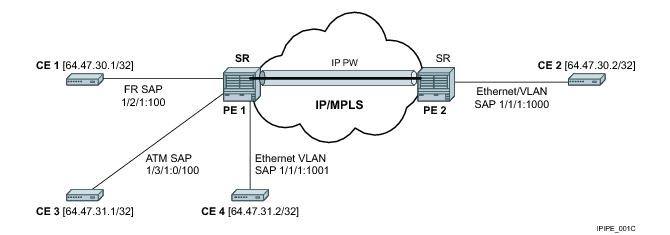
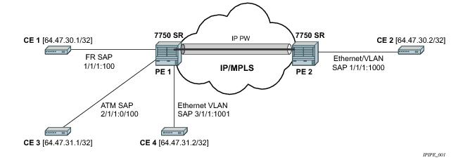
Figure 42 provides an example of IP connectivity between a host attached to a point-to-point access circuit (FR, ATM, PPP) with routed PDU IPv4 encapsulation and a host attached to an Ethernet interface. Both hosts appear to be on the same LAN segment. This feature enables service interworking between different link layer technologies. A typical use of this application is in a Layer 2 VPN when upgrading a hub site to Ethernet while keeping the spoke sites with their existing Frame Relay or ATM IPv4 routed encapsulation.
The ATM SAP carries the IPv4 packet using RFC 2684, Multiprotocol Encapsulation over ATM Adaptation Layer 5, VC-Mux or LLC/SNAP routed PDU encapsulation. The Frame Relay SAP makes use of RFC 2427
, Multiprotocol Interconnect over Frame Relay, routed PDU encapsulation of an IPv4 packet. A PPP interface makes use of RFC 1332,
The PPP Internet Protocol Control Protocol (IPCP), PPP IPCP encapsulation of an IPv4 packet. A Cisco HDLC SAP uses the routed IPv4 encapsulation. The pseudowire uses the IP Layer 2 transport pseudowire encapsulation type.
In order to be able to forward IP packets between CE 1 and CE 2 in Figure 43, PE 2 is manually configured with both CE 1 and CE 2 IP addresses. These are host addresses and are entered in /32 format. PE 2 maintains an ARP cache context for each IP interworking VLL. PE 2 responds to ARP request messages received on the Ethernet SAP. PE 2 responds with the Ethernet SAP configured MAC address as a proxy for any ARP request for CE 1 IP address. PE 2 silently discards any ARP request message received on the Ethernet SAP for an address other than that of CE 1. Likewise, PE 2 silently discards any ARP request message with the source IP address other than that of CE 2. In all cases, PE 2 keeps track of the association of IP to MAC addresses for ARP requests it receives over the Ethernet SAP.
|
•
|
The operator cannot configure the ce-address parameter under the config>service>ipipe>sap or config>service>ipipe>spoke-sdp context when the ce-address-discovery in the config>service>ipipe context is enabled. Conversely, the operator is not allowed to enable the ce-address-discovery option under the Ipipe service if it has a SAP and/or spoke SDP with a user-entered ce-address parameter.
|
|
•
|
The 7750 SR will always reply to a received ARP request message from the Ethernet SAP with the SAP MAC address and a source IP address of the IP address being ARPed without any further check of the latter.
|
|
•
|
If the operator disables the ce-address-discovery option under the VLL service, service manager instructs LDP to withdraw the service label and the service is shutdown. The pseudowire labels will only be signaled and the service will come up if the operator re-enters the option again or enters manually the ce-address parameter under SAP and spoke SDP.
|
|
•
|
The operator cannot configure the ce-address parameter under SAP or spoke SDP when the ce-address-discovery option under the VLL service is enabled. Conversely, the operator is not allowed to enable the ce-address-discovery option under the Ipipe service if it has a SAP and/or spoke SDP with a user-entered ce-address parameter.
|
|
•
|
The operator is not allowed to configure the ce-address parameter under the SAP or spoke SDP when the ce-address-discovery option under the VLL service is enabled. Conversely, the operator is not allowed to enable the ce-address-discovery option under the Ipipe service if it has a SAP and/or spoke SDP with a user-entered ce-address parameter.
|
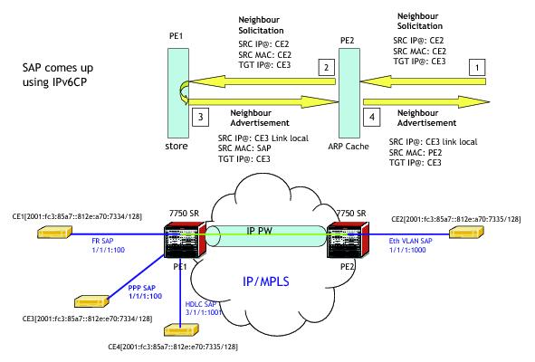
The 7750 SR supports both the transport of IPv6 packets and the interworking of IPv6 Neighbor discovery/solicitation messages on an IP Interworking VLL. IPv6 capability is enabled on an Ipipe using the
ce-address-discovery ipv6 command in the CLI.
Figure 44 illustrates the data path operation for IPv6 on an IP Interworking VLL between the Ethernet and PPP (IPv6CP) SAPs.
If the IPv6 stack is not supported by both PEs, or at least one of the PEs does support IPv6 but does not have the ce-address-discovery ipv6 option selected in the CLI, IPv6 packets received from the AC are discarded by the PE. IPv4 packets are always supported.
If IPv6 stack support is implemented by both PEs, but the ce-address-discovery ipv6 command was not enabled on both so that the IP pseudowire came up with only IPv4 support, and one PE is later toggled to
ce-address-discovery ipv6, then that PE sends a label withdraw with the LDP status code meaning “Wrong IP Address Type” (Status Code 0x0000004B9).
If the IPv6 stack is supported by both PEs, and therefore the pseudowire is established with IPv6 capability at both PEs, but the ce-address-discovery ipv6 command on one PE is later toggled to
no ce-address-discovery ipv6 so that a PE ceases to support the IPv6 stack, then that PE sends a label withdraw with the LDP status code meaning “Wrong IP Address Type”.
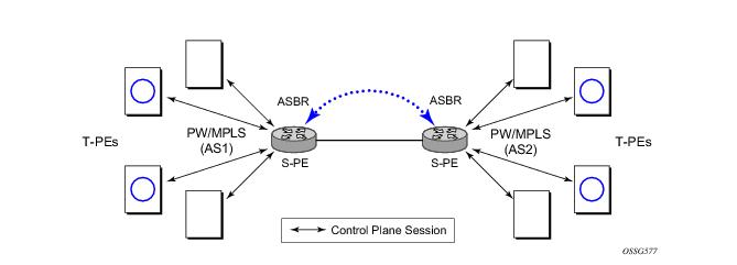
In the Figure 45, the user configures a regular Epipe VLL service PE1 and PE2. These services consist each of a SAP and a spoke SPD. However, the target destination of the SDP is actually not the remote PE but the pseudowire switching node. In addition, the user configures an Epipe VLL service on the pseudowire switching node using the two SDPs.

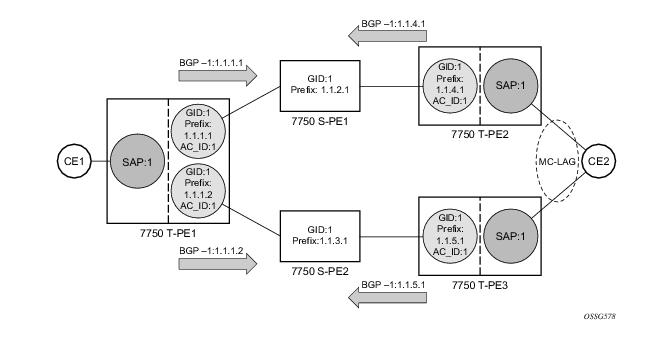
In the network in Figure 46, PE nodes act as masters and pseudowire switching nodes act as slaves for the purpose of pseudowire signaling. A switching node will need to pass the SAP Interface Parameters of each PE to the other.T-PE1 sends a label mapping message for the Layer 2 FEC to the peer pseudowire switching node” for example, S-PE1. It will include the SAP interface parameters, such as MTU, in the label mapping message. S-PE1 checks the FEC against the local information and if a match exists, it appends the optional pseudowire switching point TLV to the FEC TLV in which it records its system address. T-PE1 then relays the label mapping message to S-PE2. S-PE2 performs similar operations and forwards a label mapping message to T-PE2. The same procedures are followed for the label mapping message in the reverse direction, for example, from T-PE2 to T-PE1. S-PE1 and S-PE2 will effect the spoke SDP cross-connect only when both directions of the pseudowire have been signaled and matched.
In the network in Figure 46, PE nodes act as masters and pseudowire switching nodes act as slaves for the purpose of pseudowire signaling. This is because a switching node will need to pass the SAP interface parameters of each PE to the other.T-PE1 sends a label mapping message for the Layer 2 FEC to the peer pseudowire switching node, for example, S-PE1. It will include the SAP interface parameters, such as MTU, in the label mapping message. S-PE1 checks the FEC against the local information and if a match exists, it appends the optional pseudowire switching point TLV to the FEC TLV in which it records its system address. T-PE1 then relays the label mapping message to S-PE2. S-PE2 performs similar operation and forwards a label mapping message to T-PE2. The same procedures are followed for the label mapping message in the reverse direction, for example, from T-PE2 to T-PE1. S-PE1 and S-PE2 will effect the spoke SDP cross-connect only when both directions of the pseudowire have been signaled and matched.
0 1 2 3
0 1 2 3
0 1 2 3 4 5 6 7 8 9 0 1 2 3 4 5 6 7 8 9 0 1 2 3 4 5 6 7 8 9 0 1
+-+-+-+-+-+-+-+-+-+-+-+-+-+-+-+-+-+-+-+-+-+-+-+-+-+-+-+-+-+-+-+-+
|1|0| pw sw TLV (0x096D) | pseudowire sw TLV Length |
+-+-+-+-+-+-+-+-+-+-+-+-+-+-+-+-+-+-+-+-+-+-+-+-+-+-+-+-+-+-+-+-+
| Type | Length | Variable Length Value |
+-+-+-+-+-+-+-+-+-+-+-+-+-+-+-+-+-+-+-+-+-+-+-+-+-+-+-+-+-+-+-+-+
| Variable Length Value |
| " |
+-+-+-+-+-+-+-+-+-+-+-+-+-+-+-+-+-+-+-+-+-+-+-+-+-+-+-+-+-+-+-+-+
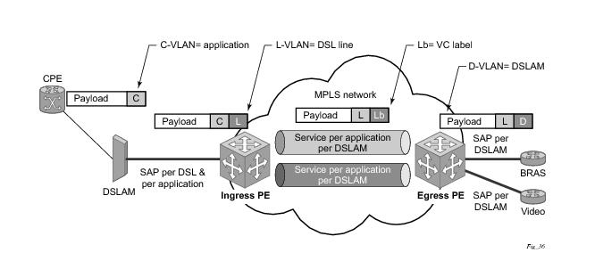
The network diagram in Figure 47 describes the network where at user access side (DSLAM facing SAPs) every subscriber is represented by several QinQ SAPs with inner-tag encoding service and outer-tag encoding subscriber (DSL line). The aggregation side (BRAS or PE facing SAPs) the is represented by DSL line number (inner VLAN tag) and DSLAM (outer VLAN tag). The effective operation on VLAN tag is to “drop inner tag at access side and push another tag at the aggregation side”.
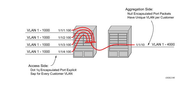
The drawing in Figure 48 indicates an application where different circuits are aggregated in the VPLS-based network.The access side is represented by an explicit do1q encapsulated SAP. As the VLAN-id is port specific, those connected to different ports might have the same VLAN. The aggregation side (the right side
Figure 48) is aggregated on the same port, and hence, unique a VLAN-id is required.
config
service
sdp 10 [mpls | GRE | [ldp-enabled] [create]
signaling <off | on>
[no] lsp <xyz>
[no] accounting-policy <policy-id>
[no] adv-mtu-override
[no] booking-factor <percentage>
[no] class-forwarding
[no] collect-stats
[no] description <description-string>
[no] far-end <ip-address> | [node-id {<ip-address> | <0…4,294,967,295>} [global-id <global-id>]]
[no] tunnel-far-end <ip-address>
[no] keep-alive
[no] mixed-lsp-mode
[no] metric <metric>
[no] network-domain <network-domain-name>
[no] path-mtu <mtu>
[no] pbb-etype <ethertype>
[no] vlan-vc-etype <ethertype>
[no] shutdown
The far-end node-id <ip-address>
global-id <global-id> command is used to associate an SDP far end with an MPLS-TP tunnel whose far end address is an MPLS-TP node ID. If the SDP is associated with an RSVP-TE LSP, then the far-end must be a routable IPv4 address.
A spoke-sdp bound to an SDP with the mpls-tp keyword cannot be no shutdown unless the ingress label, the egress label, the control word, and the pw-path-id are configured.
config
service
epipe
[no] spoke-sdp sdp-id[:vc-id]
[no] hash-label
[no]standby-signaling-slave
[no] spoke-sdp sdp-id[:vc-id] [vc-type {ether|vlan}]
[create] [vc-switching] [no-endpoint | {endpoint [icb]}]
egress
vc-label <out-label>
ingress
vc-label <in-label>
control-word
bandwidth <bandwidth>
[no] pw-path-id
agi <agi>
saii-type2 <global-id:node-id:ac-id>
taii-type2 <global-id:node-id:ac-id>
exit
[no] control-channel-status
[no] refresh-timer <value>
[no] acknowledgment
[no] shutdown
exit
The control-channel-status command enables static PW status signaling. This is valid for any spoke-sdp where
signaling none is configured on the SDP (for example, where T-LDP signaling is not in use). The refresh timer is specified in seconds, from 10-65535, with a default of 0 (off). This value can only be changed if
control-channel-status is
shutdown. Commands that rely on PW status signaling are allowed if control-channel-status is configured for a spoke-sdp bound to an SDP with signaling off, but the system will use control channel status signaling rather than T-LDP status signaling. The ability to configure control channel status signaling on a given spoke-sdp is determined by the credit based algorithm described earlier. Control-channel-status for a particular PW only counts against the credit based algorithm if it is in a no shutdown state and has a non-zero refresh timer.
The pw-path-id only configurable if all of the following is true:
The hash-label option is only configurable if SDP far-end not node-id/global-id.
The control channel status request mechanism is enabled when the request-timer <timer>parameter is non-zero. When enabled, this overrides the normal RFC-compliant refresh timer behavior. The refresh timer value in the status packet defined in RFC6478 is always set to zero. The refresh-timer in the sending node is taken from the request-timer <timer1> timer.
[no] control-channel-status
[no] refresh-timer <value> //0,10-65535, default:0
[no] request-timer <timer1> retry-timer <timer2>
[timeout-multiplier <value>]
[no] shutdown
exit
request-timer <timer1>: 0, 10-65535, defaults: 0.
retry-timer <timer2> : 3-60s
|
•
|
no status-signaling – this command causes the spoke-sdp to fall back to using PW label withdrawal as a status signaling method. However, T-LDP is not supported on MPLS-TP SDPs. Control channel status signaling should always be used for signaling PW status. Note that since active/standby dual homing into a routed VPLS requires the use of T-LDP label withdrawal as the method for status signaling, active/standby dual-homing into routed VPLS is not supported in R11.0 if the spoke-sdps are MPLS-TP.
|
|
•
|
propagate-mac-flush – This command requires the ability to receive MAC Flush messages using T-LDP signaling and so should be blocked.
|
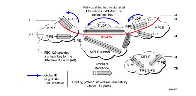
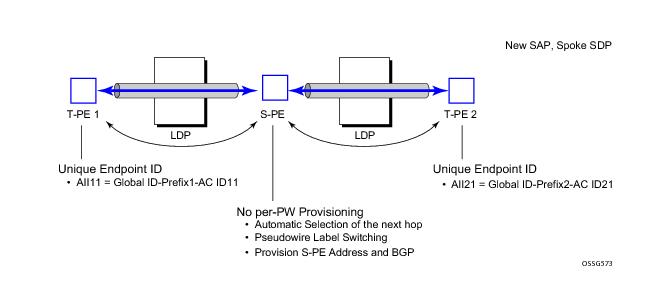
Figure 49 illustrates the operation of dynamic MS-PWs.
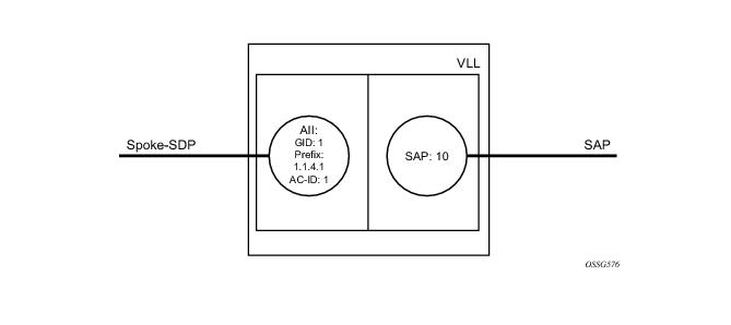
The FEC 129 AII Type 2 structure depicted in Figure 50 is used to identify each individual pseudowire endpoint:
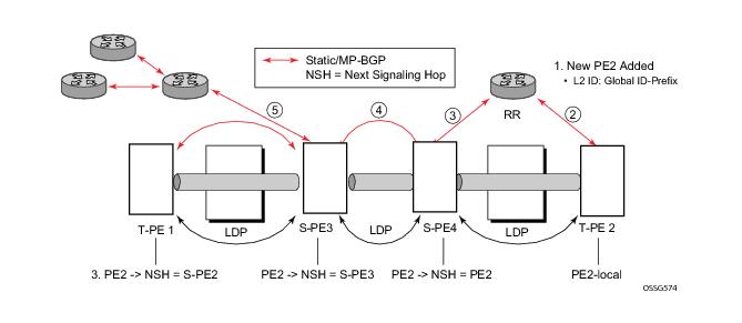
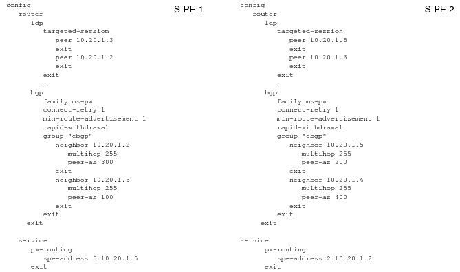
In order to enable support for dynamic MS-PWs on a 7x50 node to be used as a T-PE or S-PE, a single, globally unique, S-PE ID, known as the S-PE Address, is first configured under config>service>pw-routing on each 7x50 to be used as a T-PE or S-PE. The S-PE Address has the format global-id:prefix. It is not possible to configure any local prefixes used for pseudowire routing or to configure spoke SPDs using dynamic MS-PWs at a T-PE unless an S-PE address has already been configured. The S-PE address is used as the address of a node used to populate the switching point TLV in the LDP label mapping message and the pseudowire status notification sent for faults at an S-PE.
*A:lin-123>config>router>policy-options# info
----------------------------------------------
policy-statement "ms-pw"
default-action accept
exit
exit
----------------------------------------------
*A:lin-123>config>router>policy-options# info
----------------------------------------------
policy-statement "to-mspw"
entry 1
from
family ms-pw
exit
action accept
exit
exit
exit
----------------------------------------------
export "to-mspw"
In addition to support for BGP routing, static MS-PW routes may also be configured using the config>services>pw-routing>static-route command. Each static route comprises the target T-PE Global-ID and prefix, and the IP address of the T-LDP session to the next hop S-PE or T-PE that should be used.
A set of default explicit routes to a remote T-PE or S-PE prefix may be configured on a T-PE under config>services>pw-routing using the
path name command. Explicit paths are used to populate the explicit route TLV used by MS-PW T-LDP signaling. Only strict (fully qualified) explicit paths are supported.
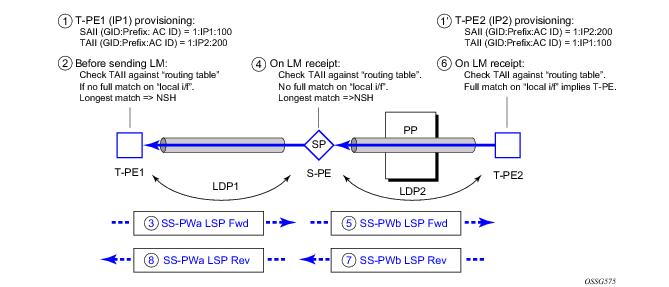
Dynamic MS-PWs use single-sided signaling procedures with double-sided configuration, a fully qualified FEC must be configured at both endpoints. That is, one T-PE (the source T-PE, ST-PE) of the MS-PW initiates signaling for the MS-PW, while the other end (the terminating T-PE, TT-PE) passively waits for the label mapping message from the far-end and only responds with a label mapping message to set up the opposite direction of the MS-PW when it receives the label mapping from the ST-PE. By default, the 7x50 will determine which T-PE is the ST-PE (the active T-PE) and which is the TT-PE (the passive T-PE) automatically, based on comparing the SAII with the TAII as unsigned integers. The T-PE with SAII>TAII assumes the active role. However, it is possible to override this behavior using the signaling {master |
auto} command under the spoke-sdp-fec. If master is selected at a given T-PE, then it will assume the active role. If a T-PE is at the endpoint of a spoke SDP that is bound to an VLL SAP and single sided auto-configuration is used (see below), then that endpoint is always passive. Therefore, signaling master should only be used when it is known that the far end will assume a passive behavior.
Automatic endpoint configuration is supported required for Epipe VLL spoke-sdp-fec endpoints bound to a VLL SAP. It is configured using the spoke-sdp-fec>auto-config command, and excluding the TAII from the configuration. When auto-configuration is used, the node assumed passive behavior from a point of view of T-LDP signaling (see above). Therefore, the far-end T-PE must be configured for signaling master for that spoke-sdp-fec.
In order to use an explicit path for an MS-PW, an explicit path must have been configured in the config>services>pw-routing>path path-name context. The user must then configure the corresponding
path path-name under
spoke-sdp-fec.
Figure 55 illustrates the use of pseudowire redundancy.
Note that the use of spoke-sdp-fec-id in vccv-ping is only applicable at T-PE nodes, since it is not configured for a given MS-PW at S-PE nodes.
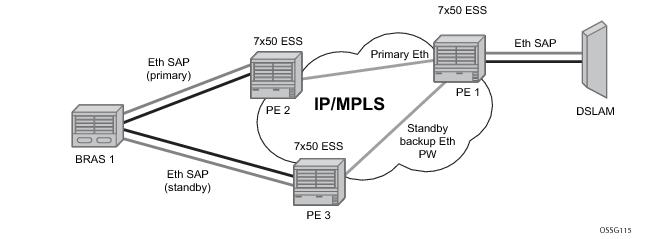
Figure 57 illustrates the application of pseudowire redundancy to provide Ethernet VLL service resilience for broadband service subscribers accessing the broadband service on the service provider BRAS.
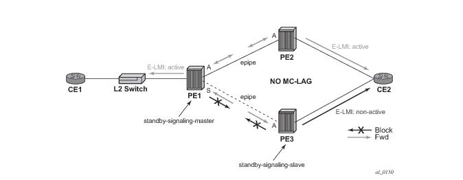
Figure 58 illustrates the operation of master-slave pseudowire redundancy. In this scenario, an Epipe service is provided between CE1 and CE2. CE2 is dual homed to PE2 and PE3, and thus PE1 is dual-homed to PE2 and PE3 using Epipe spoke SDPs. The objectives of this feature is to ensure that only one pseudowire is used for forwarding in both directions by PE1, PE2 and PE3 in the absence of a native dual homing protocol between CE2 and PE2/PE3, such as MC-LAG. In normal operating conditions (the SAPs on PE2 and PE3 towards CE2 are both up and there are no defects on the ACs to CE2), PE2 and PE3 cannot choose which spoke SDP to forward on based on the status of the AC redundancy protocol.
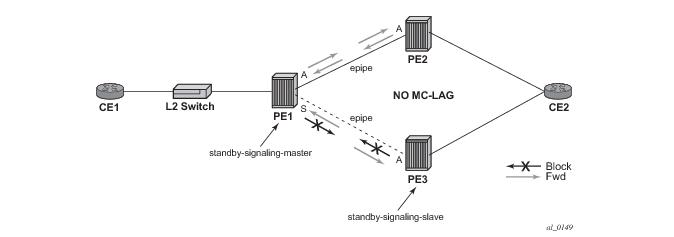
This is achieved as follows. The standby-signaling-master state is activated on the VLL endpoint in PE1. In this case, a spoke SDP is blocked in the transmit direction at this master endpoint if it is either in operDown state, or it has lower precedence than the highest precedence spoke SDP, or the given peer PE signals one of the following pseudowire status bits:
Figure 59 shows an example for the case of Ethernet LMI.
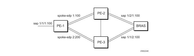
Figure 60 displays a VLL resilience path example. An sample configuration follows.
Note that a revert-time value of zero (default) means that the VLL path will be switched back to the primary immediately after it comes back up
PE1
configure service epipe 1
endpoint X
exit
endpoint Y
revert-time 0
standby-signaling-master
exit
sap 1/1/1:100 endpoint X
spoke-sdp 1:100 endpoint Y
precedence primary
spoke-sdp 2:200 endpoint Y
precedence 1
PE2
configure service epipe 1
endpoint X
exit
sap 2/2/2:200 endpoint X
spoke-sdp 1:100
standby-signaling-slave
configure service epipe 1
endpoint X
exit
sap 3/3/3:300 endpoint X
spoke-sdp 2:200
standby-signaling-slave
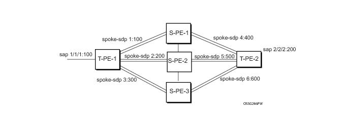
Figure 61 displays a VLL resilience for a switched pseudowire path example. A sample configuration follows.
T-PE1
configure service epipe 1
endpoint X
exit
endpoint Y
revert-time 100
standby-signaling-master
exit
sap 1/1/1:100 endpoint X
spoke-sdp 1:100 endpoint Y
precedence primary
spoke-sdp 2:200 endpoint Y
precedence 1
spoke-sdp 3:300 endpoint Y
precedence 1
T-PE2
configure service epipe 1
endpoint X
exit
endpoint Y
revert-time 100
standby-signaling-slave
exit
sap 2/2/2:200 endpoint X
spoke-sdp 4:400 endpoint Y
precedence primary
spoke-sdp 5:500 endpoint Y
precedence 1
spoke-sdp 6:600 endpoint Y
precedence 1
configure service epipe 1 vc-switching
spoke-sdp 1:100
spoke-sdp 4:400
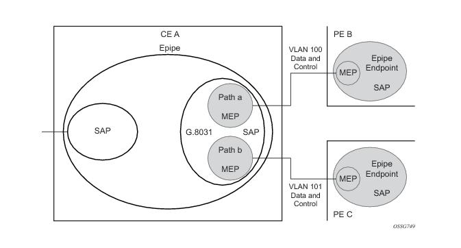
Using Epipe in combination with G.8031 and BGP Multi-Homing in the same manner as VPLS offers a multi-chassis resiliency option for Epipe services that is a non-learning and non-flooded service. Note that MC-LAG (see, Access Node Resilience Using MC-LAG and Pseudowire Redundancy) offers access node redundancy with active/stand-by links while Ethernet Tunnels offers per service redundancy with all active links and active or standby services. G.8031 offers an end to end service resiliency for Epipe and VPLS services. BGP-MH Site Support for Ethernet Tunnels offers Ethernet edge resiliency for Epipe services that integrates with MPLS Pseudowire Redundancy.
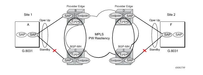
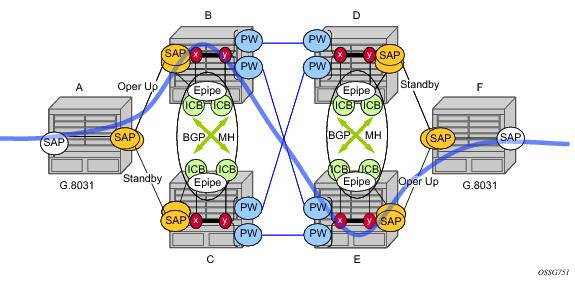
Figure 62 shows the BGP-MH Site Support for Ethernet Tunnels; where a G.8031 edge device (A) is configure to two provider edge switches (B and C). G.8031 is configured on the Access devices (A and F). An Epipe Endpoint service is configured along with BGP Multi-homing and Pseudowire Redundancy on the provider edge nodes (B,C and D,E). This configuration offers a fully redundant Epipe service.
Table 7 lists the SAP MEP signaling shown in
Figure 64. For a description of the events shown in this sample operation, see
Events in Sample Operation.
The following represents a walk through of the events for switchover in Figure 64. This configuration uses operational groups. The nodes of interest are A, B and C listed in
Table 7.
BGP Multi-Homing for VPLS describes the procedures for using BGP to control resiliency for VPLS. These procedures are the same except that an Epipe service can be configured for BGP-MH.
Pseudowire Redundancy Service Models and
Figure 67 are used for the MPLS network resiliency. BGP MH Site Support for Ethernet Tunnels reuses this model.
Using Figure 67 as a reference, the following are the rules for generating, processing, and merging T-LDP status notifications in VLL service with endpoints.
|
2.
|
If the SAP in endpoint X transitions locally to the Down state, or received a SAP Down notification via SAP specific OAM signal (SAP MEP), the node must send T-LDP SAP Down status bits on the Y endpoint ICB spoke-SDP only. BGP-MH SAP support MEPs for ifStatusTlv signaling. All other SAP types cannot exist on the same endpoint as an ICB spoke-SDP since non Ethernet SAP cannot be part of a MC-LAG instance or a BGP-MH Instance.
|
|
4.
|
If the ICB spoke-SDP in endpoint X received T-LDP SDP-binding Down status bits or PW not forwarding status bits, the node saves this status and takes no further action. The saved status is used for selecting the active transmit endpoint object as per the pseudo-code per Pseudowire Redundancy procedures.
|
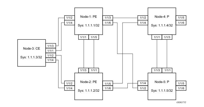
Refer to Configuration Examples for configuration examples derived from
Figure 65.
Node-1: Using operational groups and Ethernet CFM per SAP
#--------------------------------------------------
echo "Eth-CFM Configuration"
#--------------------------------------------------
eth-cfm
domain 100 format none level 3
association 2 format icc-based name "node-3-site-1-0"
bridge-identifier 1
exit
remote-mepid 310
exit
association 2 format icc-based name "node-3-site-1-1"
bridge-identifier 100
exit
remote-mepid 311
exit
exit
exit
#--------------------------------------------------
echo "Service Configuration"
#--------------------------------------------------
service
customer 1 create
description "Default customer"
exit
sdp 2 mpls create
far-end 1.1.1.4
lsp "to-node-4-lsp-1"
keep-alive
shutdown
exit
no shutdown
exit
sdp 3 mpls create // Etcetera
pw-template 1 create
vc-type vlan
exit
oper-group "og-name-et" create
exit
oper-group "og-name-et100" create
exit
epipe 1 customer 1 create
service-mtu 500
bgp
route-distinguisher 65000:1
route-target export target:65000:1 import target:65000:1
exit
site "site-1" create
site-id 1
sap 1/1/2:1.1
boot-timer 100
site-activation-timer 2
no shutdown
exit
endpoint "x" create
exit
endpoint "y" create
exit
sap 1/1/2:1.1 endpoint "x" create
eth-cfm
mep 130 domain 100 association 2 direction down
fault-propagation-enable use-if-tlv
ccm-enable
no shutdown
exit
exit
oper-group "og-name-et"
exit
spoke-sdp 2:1 endpoint "y" create
precedence primary
no shutdown
exit
spoke-sdp 3:1 endpoint "y" create
precedence 2
no shutdown
exit
no shutdown
exit
epipe 100 customer 1 create
description "Epipe 100 in separate opergroup"
service-mtu 500
bgp
route-distinguisher 65000:2
route-target export target:65000:2 import target:65000:2
exit
site "site-name-et100" create
site-id 1101
sap 1/1/4:1.100
boot-timer 100
site-activation-timer 2
no shutdown
exit
endpoint "x" create
exit
endpoint "y" create
exit
sap 1/1/4:1.100 endpoint "x" create
eth-cfm
mep 131 domain 1 association 2 direction down
fault-propagation-enable use-if-tlv
ccm-enable
no shutdown
exit
exit
oper-group "og-name-et100"
exit
spoke-sdp 2:2 vc-type vlan endpoint "y" create
precedence 1
no shutdown
exit
spoke-sdp 3:2 vc-type vlan endpoint "y" create
precedence 2
no shutdown
exit
no shutdown
exit
exit
#--------------------------------------------------
echo "BGP Configuration"
#--------------------------------------------------
bgp
rapid-withdrawal
rapid-update l2-vpn
group "internal"
type internal
neighbor 1.1.1.2
family l2-vpn
exit
exit
exit
exit
Node-3: Using operational groups and Ethernet CFM per SAP
#--------------------------------------------------
echo "Eth-CFM Configuration"
#--------------------------------------------------
eth-cfm
domain 100 format none level 3
association 2 format icc-based name "node-3-site-1-0"
bridge-identifier 1
exit
ccm-interval 1
remote-mepid 130
exit
association 2 format icc-based name "node-3-site-1-1"
bridge-identifier 100
exit
ccm-interval 1
remote-mepid 131
association 3 format icc-based name "node-3-site-2-0"
bridge-identifier 1
exit
ccm-interval 1
remote-mepid 120
exit
association 3 format icc-based name "node-3-site-2-1"
bridge-identifier 100
exit
ccm-interval 1
remote-mepid 121
exit
exit
exit
#--------------------------------------------------
echo "Service Configuration"
#--------------------------------------------------
eth-tunnel 1
description "Eth Tunnel loadsharing mode QinQ example"
protection-type loadsharing
ethernet
encap-type qinq
exit
path 1
member 1/1/3
control-tag 1.1
eth-cfm
mep 310 domain 100 association 2
ccm-enable
control-mep
no shutdown
exit
exit
no shutdown
exit
path 2
member 1/1/4
control-tag 1.2
eth-cfm
mep 320 domain 100 association 3
ccm-enablepath
control-mep
no shutdown
exit
exit
no shutdown
exit
no shutdown
exit
#--------------------------------------------------
echo "Ethernet Tunnel Configuration"
#--------------------------------------------------
eth-tunnel 2
description "Eth Tunnel QinQ"
revert-time 10
path 1
precedence primary
member 1/1/1
control-tag 1.100
eth-cfm
mep 311 domain 100 association 2
ccm-enable
control-mep
no shutdown
exit
exit
no shutdown
exit
path 2
member 1/1/2
control-tag 1.100
eth-cfm
mep 321 domain 100 association 3
ccm-enable
control-mep
no shutdown
exit
exit
no shutdown
exit
no shutdown
exit
#--------------------------------------------------
echo "Service Configuration"
#--------------------------------------------------
service
epipe 1 customer 1 create
sap 2/1/2:1.1 create
exit
sap eth-tunnel-1 create
exit
no shutdown
exit
epipe 100 customer 1 create
service-mtu 500
sap 2/1/10:1.100 create
exit
sap eth-tunnel-2 create
exit
no shutdown
exit
#--------------------------------------------------
echo "Service Configuration" Oper-groups
#--------------------------------------------------
service
customer 1 create
description "Default customer"
exit
sdp 2 mpls create
...
exit
pw-template 1 create
vc-type vlan
exit
oper-group "og-name-et" create
exit
epipe 1 customer 1 create
service-mtu 500
bgp
route-distinguisher 65000:1
route-target export target:65000:1 import target:65000:1
exit
site "site-1" create
site-id 1
sap 1/1/2:1.1
boot-timer 100
site-activation-timer 2
no shutdown
exit
endpoint "x" create
exit
endpoint "y" create
exit
sap 1/1/2:1.1 endpoint "x" create
eth-cfm
mep 130 domain 100 association 1 direction down
fault-propagation-enable use-if-tlv
ccm-enable
no shutdown
exit
exit
oper-group "og-name-et"
exit
spoke-sdp 2:1 endpoint "y" create
precedence primary
no shutdown
exit
spoke-sdp 3:1 endpoint "y" create
precedence 2
no shutdown
exit
no shutdown
exit
epipe 2 customer 1 create
description "Epipe 2 in opergroup with Epipe 1"
service-mtu 500
bgp
route-distinguisher 65000:2
route-target export target:65000:2 import target:65000:2
exit
endpoint "x" create
exit
endpoint "y" create
exit
sap 1/1/2:1.2 endpoint "x" create
monitor-oper-group "og-name-et"
exit
spoke-sdp 2:2 vc-type vlan endpoint "y" create
precedence 1
no shutdown
exit
spoke-sdp 3:2 vc-type vlan endpoint "y" create
precedence 2
no shutdown
exit
no shutdown
exit
exit
#--------------------------------------------------
echo "Eth-CFM Configuration"
#--------------------------------------------------
eth-cfm
domain 100 format none level 3
association 1 format icc-based name "node-3-site-1-0"
bridge-identifier 1
exit
ccm-interval 1
remote-mepid 130
exit
association 2 format icc-based name "node-3-site-2-0"
bridge-identifier 2
exit
ccm-interval 1
remote-mepid 120
exit
exit
exit
#--------------------------------------------------
echo "Service Configuration"
#--------------------------------------------------
eth-tunnel 2
description "Eth Tunnel loadsharing mode QinQ example"
protection-type loadsharing
ethernet
encap-type qinq
exit
path 1
member 1/1/1
control-tag 1.1
eth-cfm
mep 310 domain 100 association 1
ccm-enable
control-mep
no shutdown
exit
exit
no shutdown
exit
path 2
member 1/1/2
control-tag 1.1
eth-cfm
mep 320 domain 100 association 2
ccm-enablepath
control-mep
no shutdown
exit
exit
no shutdown
exit
no shutdown
exit
#--------------------------------------------------
echo "Service Configuration"
#--------------------------------------------------
service
epipe 1 customer 1 create
sap 1/10/1:1 create
exit
sap eth-tunnel-1 create
exit
no shutdown
exit
#--------------------------------------------------
echo "Service Configuration for a shared fate Ethernet Tunnel"
#--------------------------------------------------
epipe 2 customer 1 create
sap 1/10/2:3 create
exit
sap eth-tunnel-1:2 create
eth-tunnel
path 1 tag 1.2
path 2 tag 1.2
exit
exit
no shutdown
exit
Figure 66 shows the use of both Multi-Chassis Link Aggregation (MC-LAG) in the access network and pseudowire redundancy in the core network to provide a resilient end-to-end VLL service to the customers.
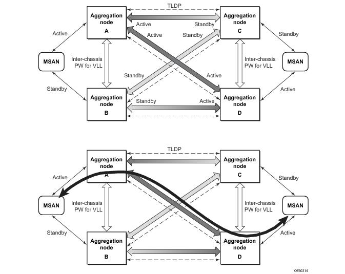
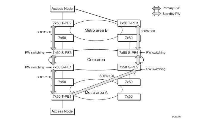
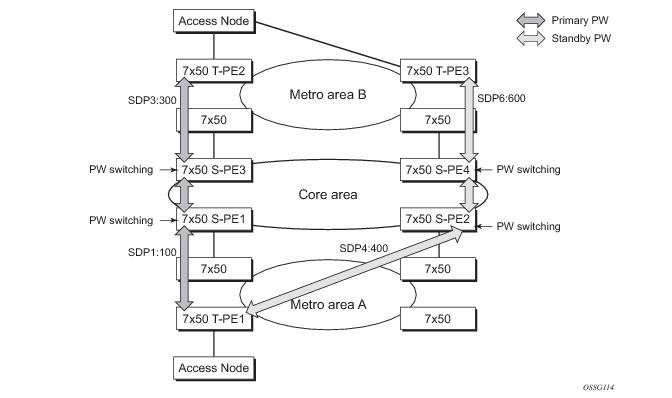
Figure 67 illustrates the use of both pseudowire redundancy and pseudowire switching to provide a resilient VLL service across multiple IGP areas in a provider network.
Like in the application in VLL Resilience with Two Destination PE Nodes, the T-PE1 node switches the path of a VLL to a secondary standby pseudowire in the case of a network side failure causing the VLL binding status to be DOWN or if T-PE2 notified it that the remote SAP went down. This application requires that pseudowire status notification messages generated by either a T-PE node or a S-PE node be processed and relayed by the S-PE nodes.
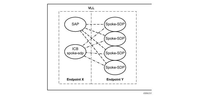
Note that Figure 68 is merely an example and that the “Y” endpoint can also have a SAP and/or an ICB spoke SDP. The following details the four types of endpoint objects supported and the rules used when associating them with an endpoint of a VLL service:
Referring to Figure 68 as a reference, the following are the rules for generating, processing, and merging T-LDP status notifications in VLL service with endpoints. Note that any allowed combination of objects as specified in
Redundant VLL Service Model can be used on endpoints “X” and “Y”. The following sections refer to the specific combination objects in
Figure 68 as an example to describe the more general rules.
The endpoint revert-time reversion from secondary to primary paths in the
config>service>apipe>endpoint and
config>service>epipe>endpoint contexts are consistent with standard pseudowire redundancy. Various network configurations and equipment require different reversion configurations. The default revert-time is 0.
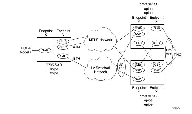
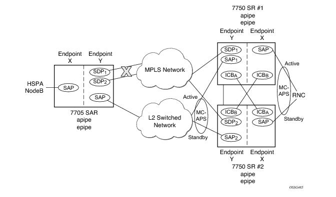
In many cases, 7750 SRs are deployed in redundant pairs at the MSC. In this case, MC-APS is typically used for all ATM connections. Figure 70 illustrates this case assuming that MC-APS is deployed on both the RNC connection and the ATM network connection. For MC-APS to be used, clear channel SONET or SDH connections should be used.
The following is an example configuration of Epipes mapping to Figure 70. Note that a SAP can be added to an endpoint with a non-ICB spoke SDP only if the spoke's precedence is
primary.
*A:ALA-A>config>service# epipe 1
----------------------------------------------
endpoint X
exit
endpoint Y
exit
sap 1/1/2:0 endpoint X
exit
spoke-sdp 1:100 endpoint X icb
exit
spoke-sdp 10:500 endpoint Y
precedence primary
exit
sap 1/1/3:0 endpoint Y
exit
spoke-sdp 1:200 endpoint Y icb
exit
----------------------------------------------
*A:ALA-A>config>service#
*A:ALA-B>config>service# epipe 1
----------------------------------------------
endpoint X
exit
endpoint Y
exit
sap 2/3/4:0 endpoint X
exit
spoke-sdp 1:200 endpoint X icb
exit
spoke-sdp 20:600 endpoint Y
precedence primary
exit
sap 2/3/5:0 endpoint Y
exit
spoke-sdp 1:100 endpoint Y icb
exit
----------------------------------------------
*A:ALA-B>config>service#
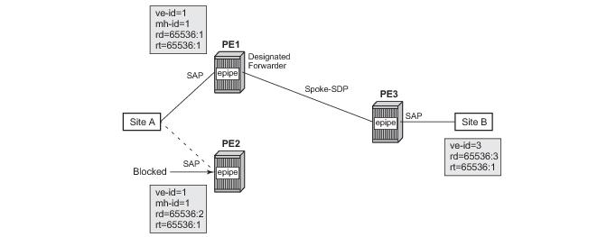
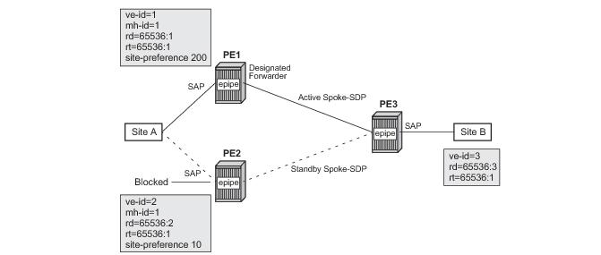
Figure 72 shows how this service would be used to provide a virtual lease-line service across an MPLS network between two sites, A and B.
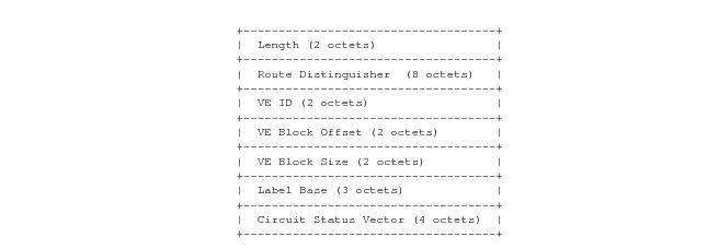
Figure 75 displays the format of the BGP VPWS update extended community.:
configure service pw-template policy-id [use-provisioned-sdp] [create]
accounting-policy acct-policy-id
no accounting-policy
[no] collect-stats
egress
filter ipv6 ipv6-filter-id
filter ip ip-filter-id
filter mac mac-filter-id
no filter [ip ip-filter-id] [mac mac-filter-id] [ipv6 ipv6-filter-id]
qos network-policy-id port-redirect-group queue-group-name instance instance-id
no qos [network-policy-id]
[no] force-vlan-vc-forwarding
hash-label [signal-capability]
no hash-label
ingress
filter ipv6 ipv6-filter-id
filter ip ip-filter-id
filter mac mac-filter-id
no filter [ip ip-filter-id] [mac mac-filter-id] [ipv6 ipv6-filter-id]
qos network-policy-id fp-redirect-group queue-group-name instance instance-id
no qos [network-policy-id]
vc-type {ether|vlan}
vlan-vc-tag vlan-id
no vlan-vc-tag
The use-provisioned-sdp command is permitted when creating the pseudowire template if a pre-provisioned SDP is to be used. Pre-provisioned SDPs must be configured whenever RSVP or BGP signaled transport tunnels are used.
The tools perform command can be used similarly as for BGP-AD to force the application of changes in pseudowire-template using the format described below:
tools perform service [id service-id] eval-pw-template policy-id [allow-service-impact]
tools perform service id <service-id> endpoint <endpoint-name> force-switchover
This section describes various of the general 7750 SR service features and any special capabilities or considerations as they relate to VLL services.
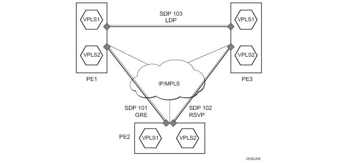
The simple three-node network described in Figure 79 shows two MPLS SDPs and one GRE SDP defined between the nodes. These SDPs connect VPLS1 and VPLS2 instances that are defined in the three nodes. With this feature the operator will have local CLI based as well as SNMP based statistics collection for each VC used in the SDPs. This will allow for traffic management of tunnel usage by the different services and with aggregation the total tunnel usage.
When applied to 7750 SR Epipe, Apipe, and Fpipe services, service ingress QoS policies only create the unicast queues defined in the policy. The multipoint queues are not created on the service.
With Epipe, Apipe, and Fpipe services, egress QoS policies function as with other services where the class-based queues are created as defined in the policy. Note that both Layer 2 or Layer 3 criteria can be used in the QoS policies for traffic classification in a service. QoS policies on Apipes cannot perform any classification and on Fpipes Layer 3 (IP) classification is performed.
7750 SR Epipe, Fpipe, and Ipipe services can have a single filter policy associated on both ingress and egress. Both MAC and IP filter policies can be used on Epipe services.
Epipe services are point-to-point layer 2 VPNs capable of carrying any Ethernet payloads. Although an Epipe is a Layer 2 service, the 7750 SR Epipe implementation does not perform any MAC learning on the service, so Epipe services do not consume any MAC hardware resources.