This section provides an overview of the 7750 SR-Series subscriber services, service model and service entities. Additional details on the individual subscriber services can be found in subsequent chapters.
In the SR-Series services can provide Layer 2/bridged service
or Layer 3/IP routed connectivity between a service access point (SAP)
on one router and another service access point (a SAP is where traffic enters and exits the service) on the same (local) router
or another router (distributed). A distributed service spans more than one router
.
Distributed services use service distribution points (SDPs) to direct traffic to another SR-Series through a service tunnel. SDPs are created on each participating router, specifying the origination address (the router participating in the service communication) and the destination address of another router. SDPs are then bound to a specific customer service. Without the binding process, far-end router is not able to participate in the service (there is no service without associating an SDP with a service).
The SR-Series offers the following types of subscriber services which are described in more detail in the referenced chapters:
Common to all SR-Series connectivity services are policies that are assigned to the service. Policies are defined at a global level and then applied to a service on the router. Policies are used to define
SR-Series service enhancements. The types of policies that are common to all
SR-Series connectivity services are:
Multipoint shared queuing is supported to minimize the number of multipoint queues created for ingress VPLS, IES or VPRN SAPs or ingress subscriber SLA profiles. Normally, ingress multipoint packets are handled by multipoint queues created for each SAP or subscriber SLA profile instance. In some instances, the number of SAPs or SLA profile instances are sufficient for the in use multipoint queues to represent many thousands of queues on an ingress forwarding plane. If multipoint shared queuing is enabled for the SAPs or SLA profile instances on the forwarding plane, the multipoint queues are not created. Instead, the ingress multipoint packets are handled by the unicast queue mapped to the forwarding class of the multipoint packet.
Functionally, multipoint shared queuing is a superset of shared queuing. With shared queuing on a SAP or SLA profile instance, only unicast packets are processed twice, once for the initial service level queuing and a second time for switch fabric destination queuing. Shared queuing does not affect multipoint packet handling. Multipoint packet handling in normal (service queuing) is the same as shared queuing. When multipoint shared queuing is enabled, shared queuing for unicast packets is automatically enabled.
Three modes of ingress SAP queuing are supported for multipoint services (IES, VPLS and VPRN); service, shared, and multipoint shared. The same ingress queuing options are available for IES and VPLS subscriber SLA profile instance queuing.
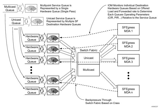
Normal or service queuing is the default mode of operation for SAP ingress queuing. Service queuing preserves ingress forwarding bandwidth by allowing a service queue defined in an ingress SAP QoS policy to be represented by a group of hardware queues. A hardware queue is created for each switch fabric destination to which the logical service queue must forward packets. For a VPLS SAP with two ingress unicast service queues, two hardware queues are used for each destination forwarding engine the VPLS SAP is forwarding to. If three switch fabric destinations are involved, six queues are allocated (two unicast service queues multiplied by three destination forwarding complexes equals six hardware queues). Figure 1 demonstrates unicast hardware
queue expansion. Service multipoint queues in the ingress SAP QoS policy are not expanded to multiple hardware queues, each service multipoint queue defined on the SAP equates to a single hardware queue to the switch fabric.
When multiple hardware queues represent a single logical service queue, the system automatically monitors the offered load and forwarding rate of each hardware queue. Based on the monitored state of each hardware queue, the system imposes an individual CIR and PIR rate for each queue that provides an overall aggregate CIR and PIR reflective of what is provisioned on the service queue.
To avoid the hardware queue expansion issues associated with normal service based queuing, the system allows an ingress logical service queue to map to a single hardware queue when shared queuing is enabled. Shared queuing uses two passes through the ingress forwarding plane to separate ingress per service queuing from the destination switch fabric queuing. In the case of shared queuing, ingress unicast service queues are created one-for-one relative to hardware queues. Each hardware queue representing a service queue is mapped to a special destination in the traffic manager that ‘forwards’ the packet back to the ingress forwarding plane allowing a second pass through the traffic manager. In the second pass, the packet is placed into a ‘shared’ queue for the destination forwarding plane. The shared queues are used by all services configured for shared queuing.
When the first SAP or SLA profile instance is configured for shared queuing on an ingress forwarding plane, the system allocates eight hardware queues per available destination forwarding plane, one queue per forwarding class. (Twenty four hardware queues are also allocated for multipoint shared traffic, but that is discussed in the following section.) The shared queue parameters that define the relative operation of the forwarding class queues are derived from the Shared Queue policy defined in the QoS CLI node. Figure 2 demonstrates shared unicast queuing.
SAP or SLA profile instance multipoint queuing is not affected by enabling shared queuing. Multipoint queues are still created as defined in the ingress SAP QoS policy and ingress multipoint packets only traverse the ingress forwarding plane a single time.
Ingress multipoint shared queuing is a variation to the unicast shared queuing defined in Ingress Shared Queuing. Ingress unicast service queues are mapped one-for-one with hardware
queues and unicast packets traverse the ingress forwarding plane twice. In addition to the above, the multipoint queues defined in the ingress SAP QoS policy are not created. Instead, multipoint packets (broadcast, multicast and unknown unicast destined) are treated to the same dual pass ingress forwarding plane processing as unicast packets. In the first pass, the forwarding plane uses the unicast queue mappings for each forwarding plane. The second pass uses the multipoint shared queues to forward the packet to the switch fabric for special replication to all egress forwarding planes that need to process the packet.
The benefit of defining multipoint shared queuing is the savings of the multipoint queues per service. By using the unicast queues in the first pass and then the aggregate shared queues in the second pass, per service multipoint queues are not required. The predominate scenario where multipoint shared queuing may be required is with subscriber managed QoS environments using a subscriber per SAP model. Usually, ingress multipoint traffic is minimal per subscriber and the extra multipoint queues for each subscriber reduces the overall subscriber density on the ingress forwarding plane. Multipoint shared queuing eliminates the multipoint queues sparing hardware queues for better subscriber density. Figure 4 demonstrates multipoint shared queuing.
One disadvantage of enabling multipoint shared queuing is that multipoint packets are no longer managed per service (although the unicast forwarding queues may provide limited benefit in this area). Multipoint packets in a multipoint service (VPLS, IES and VPRN) use significant resources in the system, consuming ingress forwarding plane multicast bandwidth and egress replication bandwidth. Usually, the per service unicast forwarding queues are not rate limited to a degree that allows adequate management of multipoint packets traversing them when multipoint shared queuing is enabled. It is possible to minimize the amount of aggregate multipoint bandwidth by setting restrictions on the multipoint queue parameters in the QoS node’s shared queue policy. Aggregate multipoint traffic can be managed per forwarding class for each of the three forwarding types (broadcast, multicast or unknown unicast – broadcast and unknown unicast are only used by VPLS).
A second disadvantage to multipoint shared queuing is the fact that multipoint traffic now consumes double the ingress forwarding plane bandwidth due to dual pass ingress processing.
The terms customers and subscribers are used synonymously. The most basic required entity is the customer ID value which is assigned when the customer account is created. To provision a service, a customer ID must be associated with the service at the time of service creation.
Each subscriber service type is configured with at least one service access point (SAP). A SAP identifies the customer interface point for a service on an Alcatel-Lucent router (
Figure 6). The SAP configuration requires that slot, XMA/MDA, and port
/channel information be specified. The slot, XMA/MDA, and port
/channel parameters must be configured prior to provisioning a service (see the
Cards, MDAs, and Ports sections of the
OS Interface Guide).
Depending on the encapsulation, a physical port or channel can have more than one SAP associated with it. SAPs can only be created on ports
or channels designated as “access” in the physical port configuration.
SAPs cannot be created on ports designated as core-facing “network” ports as these ports have a different set of features enabled in software.
The encapsulation type is an access property of a service Ethernet port or SONET/SDH or TDM channel. The appropriate encapsulation type for the port
or channel depends on the requirements to support multiple services on a single port
/channel on the associated SAP and the capabilities of the downstream equipment connected to the port
/channel. For example, a port can be tagged with IEEE 802.1Q (referred to as dot1q) encapsulation in which each individual tag can be identified with a service. A SAP is created on a given port
or channel by identifying the service with a specific encapsulation ID.
This feature introduces default SAP functionality on Dot1q-encapsulated ports. This is similar to the functionality provided by Q1* SAP on QinQ encapsulated ports, meaning that on On dot1q-encapsulated ports where a default SAP is configured, all packets with q-tags not matching any explicitly defined SAPs will be assigned to this SAP. SAPs with default QinQ encapsulation are supported in VPLS, Epipe, IES and VPRN services. Both DHCP snooping and IGMP snooping are supported for QinQ SAPs. In this context, the character “*” indicates default which means allow through. A 0 value means that it should not be there which allows the Qtag to be missing.
|
•
|
A port/channel with a dot1q or BCP-dot1q encapsulation type means the traffic for the SAP is identified based on a specific IEEE 802.1Q VLAN ID value. The VLAN ID is stripped off at SAP ingress and the appropriate VLAN ID placed on at SAP egress. As a result, VLAN IDs only have local significance, so the VLAN IDs for the SAPs for a service need not be the same at each SAP.
|
|
•
|
If a port/channel is administratively shutdown, all SAPs on that port /channel will be operationally out of service.
|
Ethernet ring protection switching offers ITU-T G.8032 specification compliance to achieve resiliency for Ethernet Layer 2 networks. G.8032 (Ethernet-ring) is built on Ethernet OAM and often referred to as Ring Automatic Protection Switching (R-APS).
To configure a distributed service from ALA-A to ALA-B, the SDP ID (1) (shown in Figure 8) must be specified in the service creation process in order to “bind” the service to the tunnel (the SDP). Otherwise, service traffic is not directed to a far-end point and the far-end device(s) cannot participate in the service (there is no service). To configure a distributed service from ALA-B to ALA-A, the SDP ID (5) must be specified.
SDP keepalives actively monitor the SDP operational state using periodic Alcatel-Lucent
SDP ping echo request and echo reply messages. Alcatel-Lucent
SDP ping is a part of Alcatel-Lucent’s suite of service diagnostics built on an Alcatel-Lucent
service-level OA&M protocol. When SDP ping is used in the SDP keepalive application, the SDP echo request and echo reply messages are a mechanism for exchanging far-end SDP status.
SDP keepalive echo request messages are only sent when the SDP is completely configured and administratively up and SDP keepalives is administratively up. If the SDP is administratively down, keepalives for the SDP are disabled.
SDP keepalive echo request messages are sent out periodically based on the configured Hello Time. An optional message length for the echo request can be configured. If max drop count echo request messages do not receive an echo reply, the SDP will immediately be brought operationally down.
Once a response is received that indicates the error has cleared and the hold down time interval has expired, the SDP will be eligible to be put into the operationally up state. If no other condition prevents the operational change, the SDP will enter the operational state.
config>service>sdp-group>group-name group-name value
group-value create
A maximum of 32 admin groups can be created. The no option is only allowed if the group-name is not referenced in a pw-template or SDP.
The admin group name must have been configured or the command is failed. The user can execute the command multiple times to include or exclude more than one admin group. The sdp-include and
sdp-exclude commands can only be used with the
use-provisioned-sdp option. If the same group name is included and excluded within the same PW template, only the exclude option will be enforced.
Any changes made to the admin group sdp-include and
sdp-exclude constraints will only be reflected in existing spoke-sdps after the following command has been executed:
Essentially an ingress loopback function will isolate the SAP or MPLS SDP Binding from the rest of the service. The Figure 9 uses a simple ePipe service to illustrate the various touch points and processing that occurs on a packet that is processed by an ingress loopback as it moves through the network element.
Figure 10 uses a simple ePipe service to illustrate the various touch points and processing that occurs on a packet that is processed by an egress loopback as it moves through the network element. Egress processing will not perform queuing functions on the egress it will only perform the functions of the forwarding plane like remarking.
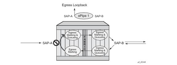
Care must be taken when considering the use of control protocols in a service with enabled loopbacks. The operator must be very aware of the impact that interrupting control protocols can have on the state of the SAP. When SAPs are dynamically created using a protocol or a protocol is required to maintain the operational state of the SAP, interruption of this control protocol will cause the SAP to fail. Other SAPs linking their state to a failed SAP will react to that failure as well. This loopback function is per Ethernet SAP or MPLS SDP Binding. This means that all traffic that is not extracted and sent to the CPM prior to the loopback process will all be looped back to in the direction it was received, or in the case of VPLS, back into the service. All service based control protocols that are included with this service should be removed to ensure the loopback process is handling the packets and not some other function on the node that can extract the control protocol but never respond because the service is block. However, there may be instances where an operator would want to continue to run control protocols for the service during a loopback. For example, Down MEPs on an Ethernet SAP could continue to process ETH-CFM packets if the loopback is on the mate Ethernet SAP and was configured as an egress loopback.
In order for the loopback function to operate the service, the SAP/ MPLS SDP Binding, the port or LAG must be operational. In the case of a LAG the LAG must have members port that are operational. If the port over which the entity is configured is not operational or the LAG has no configured members the loopback function will not loopback traffic.
In order to configure this functionality the operator is required to us use the tools hierarchy. In this specific case, the loopback tools supporting this functionality may be configured through CLI or through SNMP. However, these commands are never resident in the configuration. This means the loopback will survive high availability events that cause one CPM to change from standby to active, as well as ISSU function or IOM resets (hard or soft). However the function will not survive a complete node reboot.
Figure 11 shows an example for placing sap 1/1/10:2.2 in service id 2 (an epipe) in an active loopback mode with a mac-swap for all broadcast and multicast destined packets.
show service id 2 base
===============================================================================
Service Basic Information
===============================================================================
Service Id : 2 Vpn Id : 0
Service Type : Epipe
Name : (Not Specified)
Description : (Not Specified)
Customer Id : 1 Creation Origin : manual
Last Status Change: 07/08/2013 09:57:02
Last Mgmt Change : 07/08/2013 09:56:49
Admin State : Up Oper State : Up
MTU : 1514
Vc Switching : False
SAP Count : 2 SDP Bind Count : 0
Per Svc Hashing : Disabled
Force QTag Fwd : Disabled
-------------------------------------------------------------------------------
Service Access & Destination Points
-------------------------------------------------------------------------------
Identifier Type AdmMTU OprMTU Adm Opr
-------------------------------------------------------------------------------
sap:1/1/2:2.2 qinq 1522 1522 Up Up
sap:1/1/10:2.2 qinq 1522 1522 Up Up
===============================================================================
tools perform service id 2 loopback start sap 1/1/10:2.2 ingress mac-swap mac 00:00:00:00:00:88
tools dump service loopback
===============================================================================
Service Ethernet Loopback Points
===============================================================================
Identifier Svc ID Type Swap Swap Oper
Unicast Mlt/Br
-------------------------------------------------------------------------------
SAP 1/1/10:2.2 qinq 2 ingr SA<->DA static up
-------------------------------------------------------------------------------
No. of Service ethernet loopback points: 1
===============================================================================
tools dump service id 2 loopback sap 1/1/10:2.2
===============================================================================
Service ID 2 SAP 1/1/10:2.2 Loopback
===============================================================================
Identifier (SAP) : 1/1/10:2.2 qinq
Service ID : 2
Type : Ingress
MAC Swap
Unicast : SA<->DA
Multicast/Broadcast : Static
Static MAC : 00:00:00:00:00:88
SAP Oper State : Up
-------------------------------------------------------------------------------
Sap Statistics
-------------------------------------------------------------------------------
Last Cleared Time : N/A
Packets Octets
CPM Ingress : 491790 46721290
Forwarding Engine Stats
Dropped : 0 0
Off. HiPrio : 0 0
Off. LowPrio : 0 0
Off. Uncolor : 0 0
Off. Managed : 0 0
Queueing Stats(Ingress QoS Policy 1)
Dro. HiPrio : 0 0
Dro. LowPrio : 0 0
For. InProf : 0 0
For. OutProf : 0 0
Queueing Stats(Egress QoS Policy 1)
Dro. InProf : 0 0
Dro. OutProf : 0 0
For. InProf : 0 0
For. OutProf : 0 0
-------------------------------------------------------------------------------
===============================================================================
tools perform service id 2 loopback stop sap 1/1/10:2.2
Class based forwarding over RSVP LSPs allows a service packet to be forwarded over a specific RSVP LSP, part of an SDP, based on its ingress determined forwarding class. The LSP selected depends on the operational status and load-balancing algorithms used for ECMP and LAG spraying.
Figure 12 illustrates the use of class-based forwarding to direct packets of a service to specific RSVP or static LSPs that are part of the same SDP based on the packets' forwarding class. The forwarding class of the packet is the one assigned to the packet as a result of applying the ingress QoS policy to the service SAP. The VLL service packets are all classified into the “ef” forwarding class and those that are destined to PE2 are forwarded over LSP1. Multicast and broadcast are classified into the “be” class and are forwarded over LSP2.
This feature allows service providers to dedicate specific LSPs with a determined level of traffic engineering and protection to select service packets. For example, packets of a VoIP service are assigned the “ef” class to expedite their forwarding but are also sent over carefully traffic-engineered and FRR-protected LSP paths across the service provider network.
The 7750 SR class-based forwarding feature applies to a set of LSPs that are part of the same SDP. Each LSP must be configured as part of an SDP specifying the forwarding classes it will support. A forwarding class can only be assigned to one LSP in a given SDP, meaning that only one LSP within an SDP will support a given class of service. However, multiple classes of services can be assigned to an LSP. Both RSVP and static LSPs are allowed. All subclasses will be assigned to the same LSP as the parent forwarding class.
When a service packet is received at an ingress SAP, it is classified into one of the eight 7750 SR forwarding classes. If the packet will leave the SR on an SDP that is configured for class-based forwarding, the outgoing LSP will be selected based on the packet's forwarding class. Each SDP has a default LSP. The default LSP is used to forward a received packet that was classified at the ingress SAP into a forwarding class for which the SDP does not have an explicitly-configured LSP association. It is also used to forward a received packet if the LSP supporting its forwarding class is down. Note that the SDP goes down if the default LSP is down.
Class-based forwarding can be applied to all services supported by the 7750 SR. For VPLS services, explicit FC-to-LSP mappings are used for known unicast packets. Multicast and broadcast packets use the default LSP. There is a per-SDP user configuration that optionally overrides this behavior to specify an LSP to be used for multicast/broadcast packets.
Multi-service sites are anchor points to create an ingress and egress virtual scheduler hierarchy. When a site is created, it must be assigned to a chassis slot or port with the exception of the 7750 SR-1 in which the slot is set to 1. When scheduler policies are defined for ingress and egress, the scheduler names contained in each policy are created according to the parameters defined in the policy. Multi-service customer sites exist for the sole purpose of creating a virtual scheduler hierarchy and making it available to queues on multiple Service Access Points (SAPs).
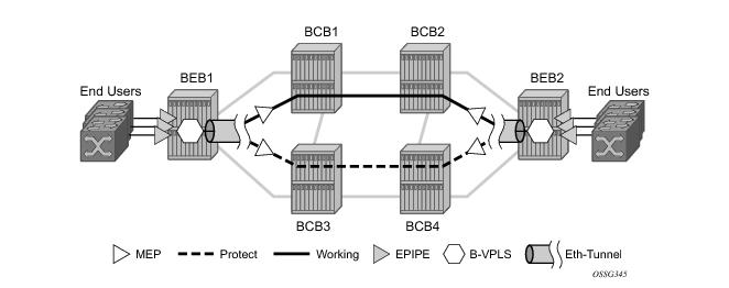
Epipe using BGP-MH site support for ethernet tunnels (see Epipe Using BGP-MH Site Support for Ethernet Tunnels) offers an enhancement to Ethernet Tunnels enabling an Ethernet edge device using G.8031 to support Multi-chassis redundancy for Epipe Services. The G.8031 device configuration is standard on the Ethernet edge device, but the active link is controlled by BGP-Multihoming just as with VPLS services. This Epipe feature offers a standards-based alternative for mulithomed access.
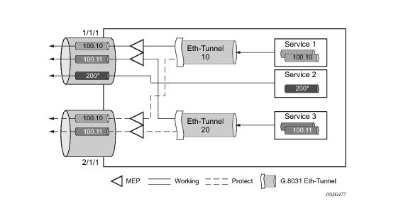
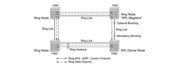
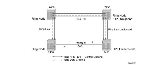
Figure 19 illustrates a resilient Ring Service. In the example a PBB ring (solid line) using VID 500 carries 2 service VLANs on I-SID 1000 and 1001 for Service VIDs (Dot1q 100 and QinQ 400.1 respectively.) The RPL for the PBB ring is between A and B where B is the RPL owner. Also illustrated is a QinQ service on the (dotted line) ring that uses Dot1q VID 600 for the ring to connect service VLAN 100.50. The two rings have RPLs on different nodes which allow a form of load balancing. The example serves to illustrate that service encapsulations and ring encapsulation can be mixed in various combinations. Also note that neither of the rings is closed loop. A ring can restore connectivity when any one node or link fails to all remaining nodes within the 50 ms transfer time (signaling time after detection).
configure eth-ring 1
description "Ring PBB BLUE on Node B"
revert-time 100
guard-time 5
ccm-hold-time down 100 up 200
rpl-node owner
path a 6/6/1 raps-tag 100 // CC Tag 100
description "To A ring link"
rpl-end
eth-cfm
mep 1 domain 1 association 1 direction down
// Control MEP
no shutdown
exit
exit
no shutdown // would allow protect switching
// in absence of the "force" cmd
exit
path b 6/6/2 raps-tag 100 //Tag 100
description "to D Ring Link"
eth-cfm
mep 1 domain 1 association 1 direction down
no shutdown
exit
exit
no shutdown
no shutdown
exit
service
vpls 10 customer 1 create // Ring APS SAPs
description "Ring Control VID 100"
sap 6/6/1:100 eth-ring 1 create
// TAG for the Control Path a
exit
sap 6/6/2:100 eth-ring 1 create
// TAG for the Control Path b
exit
no shutdown
exit
service
vpls 40 customer 1 b-vpls create //Data Channel on Ring
description "Ethernet Ring 1 VID 500"
sap 6/6/1:500 eth-ring 1 create
// TAG for the Data Channel Path a
exit
sap 6/6/2:500 eth-ring 1 create
// TAG for the Data Channel Path b
exit
exit
service vpls 1000 i-vpls // CPE traffic
sap 3/1/1:100 create // CPE SAP
pbb
backbone-vpls 40 isid 1000
exit
exit
no shutdown
exit
service vpls 1001 i-vpls // CPE traffic
sap 3/1/2:400.1 create // CPE SAP
pbb
backbone-vpls 40 isid 1001
exit
exit
no shutdown
exit
Ethernet Sub-Rings offer a dual redundant way to interconnect rings. The 7x50 supports Sub-Rings connected to major rings and a sub-ring connected to a VPLS (LDP based) for access rings support in VPLS networks. Figure 20 illustrates a Major ring and Sub Ring scenario. In this scenario, any link can fail in either ring (ERP1 or ERP2) and each ring is protected. Furthermore, the sub ring (ERP2) relies on the major Ring (ERP1) as part of its protection for the traffic from C and D. The nodes C and D are configured as inter connection nodes.
eth-ring 2
description "Ethernet Sub Ring on Ring 1"
sub-ring virtual-link // Using a virtual link
interconnect ring-id 1 // Link to Major Ring 1
propagate-topology-change
exit
exit
path a 1/1/3 raps-tag 100 // Ring control uses VID 100
eth-cfm
mep 9 domain 1 association 4
ccm-enable
control-mep
no shutdown
exit
exit
no shutdown
exit
no shutdown
exit
sub-ring non-virtual-link // Not using a virtual link
# Control Channel for the Major Ring ERP1 illustrates that Major ring
# control is still separate from Sub-ring control
vpls 10 customer 1 create
description "Control VID 10 for Ring 1 Major Ring"
stp shutdown
sap 1/1/1:10 eth-ring 1 create
stp shutdown
exit
sap 1/1/4:10 eth-ring 1 create
stp shutdown
exit
no shutdown
exit
# Data configuration for the Sub-Ring
vpls 11 customer 1 create
description "Data on VID 11 for Ring 1"
stp shutdown
sap 1/1/1:11 eth-ring 1 create // VID 11 used for ring
stp shutdown
exit
sap 1/1/4:11 eth-ring 1 create
stp shutdown
exit
sap 1/1/3:11 eth-ring 2 create // Sub-ring data
stp shutdown
exit
sap 3/2/1:1 create
description "Local Data SAP"
stp shutdown
no shutdown
exit
# Control Channel for the Sub-Ring using a virtual link. This is
# a data channel as far as Ring 1 configuration. Other Ring 1
# nodes also need this VID to be configured.
vpls 100 customer 1 create
description "Control VID 100 for Ring 2 Interconnection"
split-horizon-group "s1" create //Ring Split horizon Group
exit
stp shutdown
sap 1/1/1:100 split-horizon-group "s1" eth-ring 1 create
stp shutdown
exit
sap 1/1/4:100 split-horizon-group "s1" eth-ring 1 create
stp shutdown
exit
sap 1/1/3:100 eth-ring 2 create
stp shutdown
exit
no shutdown
exit
vpls 100 customer 1 create
description "Control VID 100 for Ring 2 Interconnection"
sap 1/1/3:100 eth-ring 2 create
stp shutdown
exit
no shutdown
exit
The 7x50 platform allows for a special configuration of the non-virtual link sub-ring that can be homed to a VPLS service illustrated in Figure 22. This is an economical way to have a redundant ring connection to a VPLS service. This is currently supported only for dot1Q and QinQ sub-rings and only on LDP based VPLS. The primary application for this is access rings that require resiliency. This configuration shows the configuration for a sub-ring at an interconnection node without a virtual channel and interconnected to a VPLS. A VPLS service 1 is used to terminate the ring control. The Ethernet ring data SAP appears in the associated LDP based VPLS service 5.
eth-ring 1
description "Ethernet Ring 1"
guard-time 20
no revert-time
rpl-node nbr
sub-ring non-virtual-link
interconnect vpls // VPLS is interconnection type
propagate-topology-change
exit
exit
path a 1/1/3 raps-tag 1.1
description "Ethernet Ring : 1 Path on LAG"
eth-cfm
mep 8 domain 1 association 8
ccm-enable
control-mep
no shutdown
exit
exit
no shutdown
exit
no shutdown
exit
# Configuration for the ring control interconnection termination:
vpls 1 customer 1 create
description "Ring 1 Control termination"
stp shutdown
sap 1/1/3:1.1 eth-ring 1 create //path a control
stp shutdown
exit
no shutdown
exit
# Configuration for the ring data into the LDP based VPLS Service
vpls 5 customer 1 create
description "VPLS Service at PE1"
stp
no shutdown
exit
sap 1/1/3:2.2 eth-ring 1 create
stp shutdown
exit
sap 1/1/5:1 create
exit
mesh-sdp 5001:5 create //sample LDP MPLS LSPs
exit
mesh-sdp 5005:5 create
exit
mesh-sdp 5006:5 create
exit
no shutdown
exit
Ethernet-rings and sub-rings offer a way to build a scalable resilient Ethernet transport network. Figure 236 illustrates a hierarchical ring network using PBB where dual homed services are connected to a PBB based Ethernet ring network. The major rings are connected by sub-rings to the top level major ring. These sub-rings require virtual channel and will not work with non-virtual channel. Ring flushing is contained to major rings, or in the case of a sub-ring link or node failure, to the sub-ring and the directly attached major rings.
Ethernet CFM is enabled by configuring MEPs on each individual path under an Ethernet ring. Only down MEPs can be configured on each of them and optionally,
CCM sessions can be enabled to monitor the liveliness of the path using interval of 10 or 100 msec. Different CCM intervals can be supported on the path a and path b in an Ethernet ring. CFM is optional if hardware supports Loss of Signal (LOS) for example, which is controlled by configuring
no-ccm-enable.
When Ethernet ring is configured on two ports located on different IOMs, the SAP queues and virtual schedulers will be created with the actual parameters on each IOM.
Figure 24 displays the overall process to provision core and subscriber services.
Subscriber services tasks include the following:


