For feedback, use the following:
ipd_online_feedback@alcatel-lucent.com
Table of Contents Previous Next Index PDF


Virtual Private LAN Service
In This Chapter
This chapter provides information about Virtual Private LAN Service (VPLS), process overview, and implementation notes.
Topics in this chapter include:
VPLS Service Overview
Virtual Private LAN Service (VPLS) as described in RFC 4905, Encapsulation methods for transport of layer 2 frames over MPLS, is a class of virtual private network service that allows the connection of multiple sites in a single bridged domain over a provider-managed IP/MPLS network. The customer sites in a VPLS instance appear to be on the same LAN, regardless of their location. VPLS uses an Ethernet interface on the customer-facing (access) side which simplifies the LAN/WAN boundary and allows for rapid and flexible service provisioning.
VPLS offers a balance between point-to-point Frame Relay service and outsourced routed services (VPRN). VPLS enables each customer to maintain control of their own routing strategies. All customer routers in the VPLS service are part of the same subnet (LAN) which simplifies the IP addressing plan, especially when compared to a mesh constructed from many separate point-to-point connections. The VPLS service management is simplified since the service is not aware of nor participates in the IP addressing and routing.
A VPLS service provides connectivity between two or more SAPs on one (which is considered a local service) or more (which is considered a distributed service) service routers. The connection appears to be a bridged domain to the customer sites so protocols, including routing protocols, can traverse the VPLS service.
Other VPLS advantages include:
 
 
VPLS Packet Walkthrough
This section provides an example of VPLS processing of a customer packet sent across the network (Figure 1) from site-A, which is connected to PE-Router-A, to site-B, which is connected to PE-Router-C (Figure 2).
Figure 1: VPLS Service Architecture
1.
a.
Figure 2: Access Port Ingress Packet Format and Lookup
b.
c.
For a Known MAC Address (Figure 3):
d.
e.
For an Unknown MAC Address (Figure 3):
If the destination MAC address has not been learned, PE-Router-A will flood the packet to both PE-Router-B and PE-Router-C that are participating in the service by using the VC-labels that each PE-Router previously signaled for the VPLS instance. Note that the packet is not sent to PE-Router-D since this VPLS service does not exist on that PE-router.
Figure 3: Network Port Egress Packet Format and Flooding
 
2.
a.
3.
a.
b.
c.
Known MAC address (Figure 4)
d.
Figure 4: Access Port Egress Packet Format and Lookup
VPLS Features
This section features:
 
VPLS Enhancements
­Alcatel-Lucent’s VPLS implementation includes several enhancements beyond basic VPN connectivity. The following VPLS features can be configured individually for each VPLS service instance:
 
VPLS over MPLS
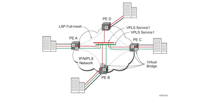
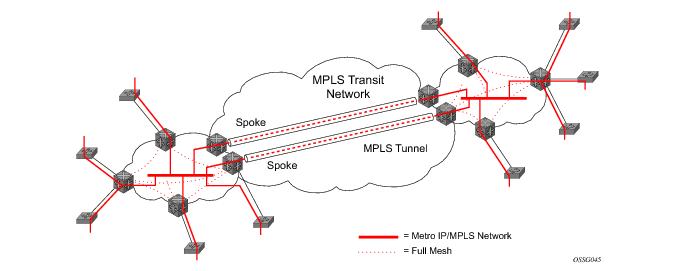
The VPLS architecture proposed in RFC 4762, Virtual Private LAN Services Using LDP Signalling specifies the use of provider equipment (PE) that is capable of learning, bridging, and replication on a per-VPLS basis. The PE routers that participate in the service are connected using MPLS Label Switched Path (LSP) tunnels in a full-mesh composed of mesh SDPs or based on an LSP hierarchy (Hierarchical VPLS (H-VPLS)) composed of mesh SDPs and spoke SDPs.
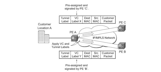
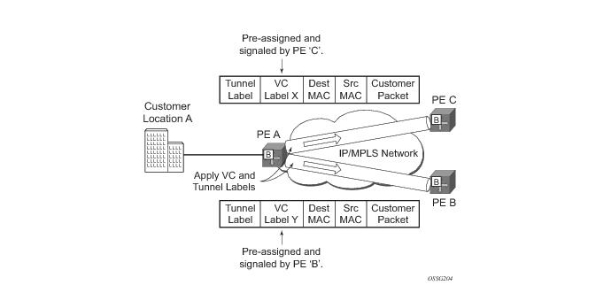
Multiple VPLS services can be offered over the same set of LSP tunnels. Signaling specified in RFC 4905, Encapsulation methods for transport of layer 2 frames over MPLS is used to negotiate a set of ingress and egress VC labels on a per-service basis. The VC labels are used by the PE routers for de-multiplexing traffic arriving from different VPLS services over the same set of LSP tunnels.
VPLS is provided over MPLS by:
Negotiating per-service VC labels using draft-Martini encapsulation.
 
 
VPLS MAC Learning and Packet Forwarding
The 7750 SR edge devices perform the packet replication required for broadcast and multicast traffic across the bridged domain. MAC address learning is performed by the 7750 SRto reduce the amount of unknown destination MAC address flooding.
7750 SR routers learn the source MAC addresses of the traffic arriving on their access and network ports.
Each 7750 SR maintains a Forwarding Information Base (FIB) for each VPLS service instance and learned MAC addresses are populated in the FIB table of the service. All traffic is switched based on MAC addresses and forwarded between all participating nodes using the LSP tunnels. Unknown destination packets (for example, the destination MAC address has not been learned) are forwarded on all LSPs to all participating nodes for that service until the target station responds and the MAC address is learned by the routers associated with that service.
 
MAC Learning Protection
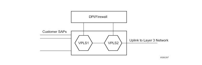
In a Layer 2 environment, subscribers connected to SAPs A, B, C can create a denial of service attack by sending packets sourcing the gateway MAC address. This will move the learned gateway MAC from the uplink SDP/SAP to the subscriber’s SAP causing all communication to the gateway to be disrupted. If local content is attached to the same VPLS (D), a similar attack can be launched against it. Communication between subscribers is also disallowed but split-horizon will not be sufficient in the topology depicted in Figure 5.
Figure 5: MAC Learning Protection
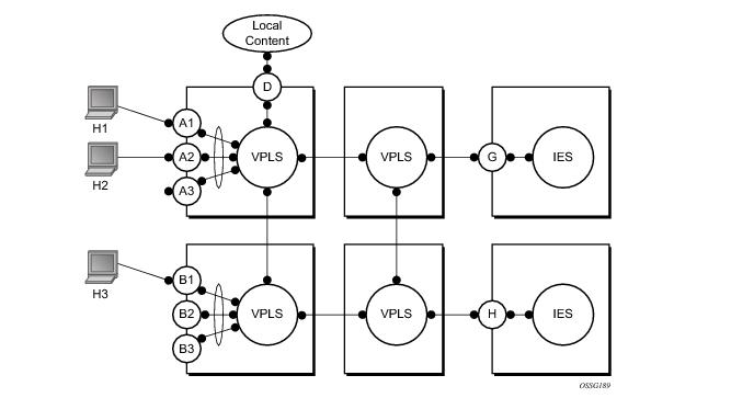
7750 SRs enable MAC learning protection capability for SAPs and SDPs. With this mechanism, forwarding and learning rules apply to the non-protected SAPs. Assume hosts H1, H2 and H3 (Figure 5) are non-protected while IES interfaces G and H are protected. When a frame arrives at a protected SAP/SDP the MAC is learned as usual. When a frame arrives from a non-protected SAP or SDP the frame must be dropped if the source MAC address is protected and the MAC address is not relearned. The system allows only packets with a protected MAC destination address.
The system can be configured statically. The addresses of all protected MACs are configured. Only the IP address can be included and use a dynamic mechanism to resolve the MAC address (cpe-ping). All protected MACs in all VPLS instances in the network must be configured.
In order to eliminate the ability of a subscriber to cause a DOS attack, the node restricts the learning of protected MAC addresses based on a statically defined list. In addition the destination MAC address is checked against the protected MAC list to verify that a packet entering a restricted SAP has a protected MAC as a destination.
 
DEI in IEEE 802.1ad
IEEE 802.1ad-2005 standard allows drop eligibility to be conveyed separately from priority in Service VLAN TAGs (STAGs) so that all of the previously introduced traffic types can be marked as drop eligible. The Service VLAN TAG has a new format where the priority and discard eligibility parameters are conveyed in the three bit Priority Code Point (PCP) field and respectively in the DE Bit (Figure 6).
Figure 6: DE Bit in the 802.1ad S-TAG
The DE bit allows the S-TAG to convey eight forwarding classes/distinct emission priorities, each with a drop eligible indication.
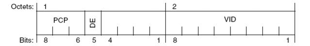
When DE bit is set to 0 (DE=FALSE), the related packet is not discard eligible. This is the case for the packets that are within the CIR limits and must be given priority in case of congestion. If the DEI is not used or backwards compliance is required the DE bit should be set to zero on transmission and ignored on reception.
When the DE bit is set to 1 (DE=TRUE), the related packet is discard eligible. This is the case for the packets that are sent above the CIR limit (but below the PIR). In case of congestion these packets will be the first ones to be dropped.
 
 
VPLS Using G.8031 Protected Ethernet Tunnels
The use of MPLS tunnels provides a way to scale the core while offering fast failover times using MPLS FRR. In environments where Ethernet services are deployed using native Ethernet backbones Ethernet tunnels are provided to achieve the same fast failover times as in the MPLS FRR case. There are still service provider environments where Ethernet services are deployed using native Ethernet backbones.
The Alcatel-Lucent VPLS implementation offers the capability to use core Ethernet tunnels compliant with ITU-T G.8031 specification to achieve 50 ms resiliency for backbone failures. This is required to comply with the stringent SLAs provided by service providers in the current competitive environment. The implementation also allows a LAG-emulating Ethernet Tunnel providing a complimentary native Ethernet ELAN capability. The LAG-emulating Ethernet tunnels and G.8031 protected Ethernet tunnels operate independently. (refer to LAG emulation using Ethernet Tunnels)
When using Ethernet Tunnels, the Ethernet Tunnel logical interface is created first. = The Ethernet tunnel has member ports which are the physical ports supporting the links. The Ethernet tunnel control SAPs carries G.8031 and 802.1ag control traffic and user data traffic. Ethernet Service SAPs are configured on the Ethernet tunnel. Optionally when tunnels follow the same paths end to end services may be configured with, Same-fate Ethernet tunnel SAPs which carry only user data traffic and shares the fate of the Ethernet tunnel port (if properly configured).
When configuring VPLS and BVPLS using Ethernet tunnels the services are very similar. Refer to PBB Using G.8031 Protected Ethernet-Tunnels for examples.
 
Pseudowire Control Word
The control word command enables the use of the control word individually on each mesh-sdp or spoke-sdp. By default, the control word is disabled. When the control word is enabled, all VPLS packets, including the BPDU frames are encapsulated with the control word. The T-LDP control plane behavior will be the same as the control word for VLL services. The configuration for the two directions of the Ethernet pseudowire should match.
 
Table Management
The following sections describe VPLS features related to management of the Forwarding Information Base (FIB).
 
FIB Size
The following MAC table management features are required for each instance of a SAP or spoke SDP within a particular VPLS service instance:
 
FIB Size Alarms
The size of the VPLS FIB can be configured with a low watermark and a high watermark, expressed as a percentage of the total FIB size limit. If the actual FIB size grows above the configured high watermark percentage, an alarm is generated. If the FIB size falls below the configured low watermark percentage, the alarm is cleared by the system.
 
Local and Remote Aging Timers
Like a Layer 2 switch, learned MACs within a VPLS instance can be aged out if no packets are sourced from the MAC address for a specified period of time (the aging time). In each VPLS service instance, there are independent aging timers for locally learned MAC and remotely learned MAC entries in the forwarding database (FIB). A local MAC address is a MAC address associated with a SAP because it ingressed on a SAP. A remote MAC address is a MAC address received by an SDP from another router for the VPLS instance. The local-age timer for the VPLS instance specifies the aging time for locally learned MAC addresses, and the remote-age timer specifies the aging time for remotely learned MAC addresses.
In general, the remote-age timer is set to a longer period than the local-age timer to reduce the amount of flooding required for destination unknown MAC addresses. The aging mechanism is considered a low priority process. In most situations, the aging out of MAC addresses can happen in within tens of seconds beyond the age time. To minimize overhead, local MAC addresses on a LAG port and remote MAC addresses, in some circumstances, can take up to two times their respective age timer to be aged out.
 
Disable MAC Aging
The MAC aging timers can be disabled which will prevent any learned MAC entries from being aged out of the FIB. When aging is disabled, it is still possible to manually delete or flush learned MAC entries. Aging can be disabled for learned MAC addresses on a SAP or a spoke SDP of a VPLS service instance.
 
Disable MAC Learning
When MAC learning is disabled for a service, new source MAC addresses are not entered in the VPLS FIB, whether the MAC address is local or remote. MAC learning can be disabled for individual SAPs or spoke SDPs.
 
Unknown MAC Discard
Unknown MAC discard is a feature which discards all packets ingressing the service where the destination MAC address is not in the FIB. The normal behavior is to flood these packets to all end points in the service.
Unknown MAC discard can be used with the disable MAC learning and disable MAC aging options to create a fixed set of MAC addresses allowed to ingress and traverse the service.
 
VPLS and Rate Limiting
Traffic that is normally flooded throughout the VPLS can be rate limited on SAP ingress through the use of service ingress QoS policies. In a service ingress QoS policy, individual queues can be defined per forwarding class to provide shaping of broadcast traffic, MAC multicast traffic and unknown destination MAC traffic.
 
MAC Move
The MAC move feature is useful to protect against undetected loops in a VPLS topology as well as the presence of duplicate MACs in a VPLS service.
If two clients in the VPLS have the same MAC address, the VPLS will experience a high re-learn rate for the MAC. When MAC move is enabled, the 7750 SR will shut down the SAP or spoke SDP and create an alarm event when the threshold is exceeded.
MAC move allows sequential order port blocking. By configuration, some VPLS ports can be configured as “non-blockable” which allows simple level of control which ports are being blocked during loop occurrence. There are two sophisticated control mechanisms that allow blocking of ports in a sequential order:
1.
2.
For the first, configuration CLI is extended by definition of “primary” and “secondary” ports. Per default, all VPLS ports are considered “tertiary” ports unless they are explicitly declared primary or secondary. The order of blocking will always follow a strict order starting from “tertiary” to secondary and then primary.
The definition of criteria for the second control mechanism is the number of periods during which the given re-learn rate has been exceeded. The mechanism is based on the “cumulative” factor for every group of ports. Tertiary VPLS ports are blocked if the re-learn rate exceeds the configured threshold during one period while secondary ports are blocked only when re-learn rates are exceeded during two consecutive periods, and so forth. The retry timeout period must be larger than the period before blocking the “highest priority port” so it sufficiently spans across the period required to block all ports in sequence. The period before blocking the “highest priority port” is the cumulative factor of the highest configured port multiplied by 5 seconds (the retry timeout can be configured through the CLI).
 
Auto-Learn MAC Protect
This section provides information about auto-learn-mac-protect and restrict-protected-src discard-frame features.
VPLS solutions usually involve learning of MAC addresses in order for traffic to be forwarded to the correct SAP/SDP. If a MAC address is learned on the wrong SAP/SDP then traffic would be re-directed away from its intended destination. This could occur through a mis-configuration, a problem in the network or by a malicious source creating a DOS attack and is applicable to any type of VPLS network, for example mobile backhaul or residential service delivery networks. auto-learn-mac-protect can be used to safe-guard against the possibility of MAC addresses being learned on the wrong SAP/SDP.
This feature provides the ability to automatically protect source MAC addresses which have been learned on a SAP or a spoke/mesh-SDP and prevent frames with the same protected source MAC address from entering into a different SAP/spoke or mesh-SDP.
This is a complementary solution to features such as mac-move and mac-pinning, but has the advantage that MAC moves are not seen and it has a low operational complexity. It should be noted that if a MAC is initially learned on the wrong SAP/SDP, the operator can clear the MAC from the MAC FDB in order for it to be re-learned on the correct SAP/SDP.
Two separate commands are used which provide the configuration flexibility of separating the identification (learning) function from the application of the restriction (discard).
The auto-learn-mac-protect and restrict-protected-src commands allow the following functions:
Note, if auto-learn-mac-protect or restrict-protected-src discard-frame is configured under an SHG the operation applies only to SAPs in the SHG not to spoke SDPs in the SHG. If required, these parameters can also be enabled explicitly under specific SAPs/spoke-SDPs within the SHG.
Applying or removing auto-learn-mac-protect or restrict-protected-src discard-frame to/from a SAP, spoke or mesh-SDP or SHG, will clear the MACs on the related objects (for the SHG, this results in clearing the MACs only on the SAPs within the SHG).
The use of restrict-protected-src discard-frame is mutually exclusive with both the restrict-protected-src [alarm-only] command and with the configuration of manually protected MAC addresses, using the mac-protect command, within a given VPLS.
The following rules govern the changes to the state of protected MACs:
If a MAC address does legitimately move between SAPs/spoke or mesh-SDPs after it has been automatically protected on a given SAP/spoke or mesh-SDP (thereby causing discards when received on the new SAP/spoke or mesh-SDP), the operator must manually clear the MAC from the FDB for it to be learned in the new/correct location.
MAC addresses that are manually created (using static-mac, static-host with a MAC address specified or oam mac-populate) will not be protected even if they are configured on a SAP/x-SDP that has auto-learn-mac-protect enabled on it.
MAC addresses that are dynamically created (learned, using static-host with no MAC address specified or lease-populate) will be protected when the MAC address is “learned” on a SAP/x- SDP that has auto-learn-mac-protect enabled on it.
The actions of the following features are performed in the order listed.
1.
2.
3.
 
Operation
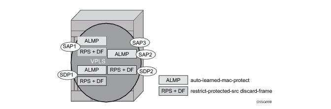
Figure 7 shows a specific configuration using auto-learn-mac-protect and restrict-protected-src discard-frame in order to describe their operation.
Figure 7: Auto-Learn-Mac-Protect Operation
A VPLS service is configured with SAP1 and SDP1 connecting to access devices and SAP2, SAP3 and SDP2 connecting to the core of the network. auto-learn-mac-protect is enabled on SAP1, SAP3 and SDP1 and restrict-protected-src discard-frame is enabled on SAP1, SDP1 and SDP2. The following series of events describe the details of the functionality:
Assume that the FDB is empty at the start of each sequence.
Sequence 1:
1.
2.
3.
4.
Sequence 2:
1.
2.
3.
4.
Sequence 3:
1.
2.
Sequence 4:
1.
2.
3.
4.
 
 
Example Use
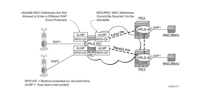
Figure 8 shows a possible configuration using auto-learn-mac-protect and restrict-protected-src discard-frame in a mobile backhaul network, with the focus on PE1.
Figure 8: Auto-Learn-Mac-Protect Example
In order to protect the MAC addresses of the BNG/RNCs on PE1, auto-learn-mac-protect is enabled on the pseudo-wires connecting it to PE2 and PE3. Enabling restrict-protected-src discard-frame on the SAPs towards the eNodeBs will prevent frames with the source MAC addresses of the BNG/RNCs from entering PE1 from the eNodeBs.
The MAC addresses of the eNodeBs are protected in two ways. In addition to the above commands, enabling auto-learn-mac-protect on the SAPs towards the eNodeBs will prevent the MAC addresses of the eNodeBs being learned on the wrong eNodeB SAP. Enabling restrict-protected-src discard-frame on the pseudowires connecting PE1 to PE2 and PE3 will protect the eNodeB MAC addresses from being learned on the pseudowires. This may happen if their MAC addresses are incorrectly injected into VPLS 40 on PE2/PE3 from another eNodeB aggregation PE.
The above configuration is equally applicable to other Layer 2 VPLS based aggregation networks, for example to business or residential service networks.
 
 
Split Horizon SAP Groups and Split Horizon Spoke SDP Groups
Within the context of VPLS services, a loop-free topology within a fully meshed VPLS core is achieved by applying a split-horizon forwarding concept that packets received from a mesh SDP are never forwarded to other mesh SDPs within the same service. The advantage of this approach is that no protocol is required to detect loops within the VPLS core network.
In applications such as DSL aggregation, it is useful to extend this split-horizon concept also to groups of SAPs and/or spoke SDPs. This extension is referred to as a split horizon SAP group or residential bridging.
Traffic arriving on a SAP or a spoke SDP within a split horizon group will not be copied to other SAPs and spoke SDPs in the same split horizon group (but will be copied to SAPs / spoke SDPs in other split horizon groups if these exist within the same VPLS).
 
VPLS and Spanning Tree Protocol
­Alcatel-Lucent’s VPLS service provides a bridged or switched Ethernet Layer 2 network. Equipment connected to SAPs forward Ethernet packets into the VPLS service. The 7750 SR participating in the service learns where the customer MAC addresses reside, on ingress SAPs or ingress SDPs.
Unknown destinations, broadcasts, and multicasts are flooded to all other SAPs in the service. If SAPs are connected together, either through misconfiguration or for redundancy purposes, loops can form and flooded packets can keep flowing through the network. Alcatel-Lucent’s implementation of the Spanning Tree Protocol (STP) is designed to remove these loops from the VPLS topology. This is done by putting one or several SAPs and/or spoke SDPs in the discarding state.
Alcatel-Lucent’s implementation of the Spanning Tree Protocol (STP) incorporates some modifications to make the operational characteristics of VPLS more effective.
The STP instance parameters allow the balancing between resiliency and speed of convergence extremes. Modifying particular parameters can affect the behavior. For information on command usage, descriptions, and CLI syntax, refer to Configuring a VPLS Service with CLI.
 
Spanning Tree Operating Modes
Per VPLS instance, a preferred STP variant can be configured. The STP variants supported are:
rstp — Rapid Spanning Tree Protocol (RSTP) compliant with IEEE 802.1D-2004 - default mode
dot1w — Compliant with IEEE 802.1w
comp-dot1w — Operation as in RSTP but backwards compatible with IEEE 802.1w
(this mode allows interoperability with some MTU types)
mstp — Compliant with the Multiple Spanning Tree Protocol specified in IEEE 802.1Q-REV/D5.0-09/2005. This mode of operation is only supported in an mVPLS.
While the 7750 SR initially uses the mode configured for the VPLS, it will dynamically fall back (on a per-SAP basis) to STP (IEEE 802.1D-1998) based on the detection of a BPDU of a different format. A trap or log entry is generated for every change in spanning tree variant.
Some older 802.1W compliant RSTP implementations may have problems with some of the features added in the 802.1D-2004 standard. Interworking with these older systems is improved with the comp-dot1w mode. The differences between the RSTP mode and the comp-dot1w mode are:
The 7750 SR supports two BDPU encapsulation formats, and can dynamically switch between the following supported formats (on a per-SAP basis):
 
Multiple Spanning Tree
The Multiple Spanning Tree Protocol (MSTP) extends the concept of the IEEE 802.1w Rapid Spanning Tree Protocol (RSTP) by allowing grouping and associating VLANs to Multiple Spanning Tree Instances (MSTI). Each MSTI can have its own topology, which provides architecture enabling load balancing by providing multiple forwarding paths. At the same time, the number of STP instances running in the network is significantly reduced as compared to Per VLAN STP (PVST) mode of operation. Network fault tolerance is also improved because a failure in one instance (forwarding path) does not affect other instances.
The SR-Series implementation of Management VPLS (mVPLS) is used to group different VPLS instances under single RSTP instance. Introducing MSTP into the mVPLS allows interoperating with traditional Layer 2 switches in access network and provides an effective solution for dual homing of many business Layer 2 VPNs into a provider network.
 
Redundancy Access to VPLS
The GigE MAN portion of the network is implemented with traditional switches. Using MSTP running on individual switches facilitates redundancy in this part of the network. In order to provide dual homing of all VPLS services accessing from this part of the network, the VPLS PEs must participate in MSTP.
This can be achieved by configuring mVPLS on VPLS-PEs (only PEs directly connected to GigE MAN network) and then assign different managed-vlan ranges to different MSTP instances. Typically, the mVPLS would have SAPs with null encapsulations (to receive, send, and transmit MSTP BPDUs) and a mesh SDP to interconnect a pair of VPLS PEs.
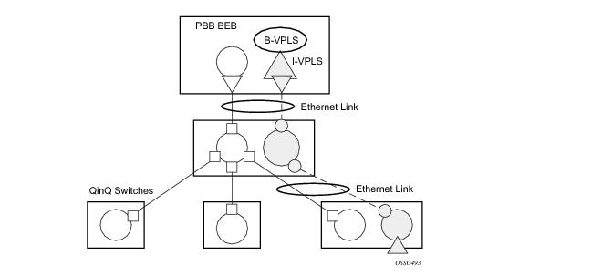
Different access scenarios are displayed in Figure 9 as example network diagrams dually connected to the PBB PEs:
Access Type A — Source devices connected by null or Dot1q SAPs
Access Type B — One QinQ switch connected by QinQ/801ad SAPs
Access Type C — Two or more ES devices connected by QinQ/802.1ad SAPs
Figure 9: Access Resiliency
The following mechanisms are supported for the I-VPLS:
STP/RSTP can be used for all access types.
M-VPLS with MSTP can be used as is just for access Type A. MSTP is required for access type B and C.
LAG and MC-LAG can be used for access Type A and B.
Split-horizon-group does not require residential.
PBB I-VPLS inherits current STP configurations from the regular VPLS and MVPLS.
 
MSTP for QinQ SAPs
MSTP runs in a MVPLS context and can control SAPs from source VPLS instances. QinQ SAPs are supported. The outer tag is considered by MSTP as part of VLAN range control
 
Provider MSTP
Provider MSTP is specified in (IEEE-802.1ad-2005). It uses a provider bridge group address instead of a regular bridge group address used by STP, RSTP, MSTP BPDUs. This allows for implicit separation of source and provider control planes.
The 802.1ad access network sends PBB PE P-MSTP BPDUs using the specified MAC address and also works over QinQ interfaces. P-MSTP mode is used in PBBN for core resiliency and loop avoidance.
Similar to regular MSTP, the STP mode (for example, PMSTP) is only supported in VPLS services where the m-VPLS flag is configured.
 
 
MSTP General Principles
MSTP represents modification of RSTP which allows the grouping of different VLANs into multiple MSTIs. To enable different devices to participate in MSTIs, they must be consistently configured. A collection of interconnected devices that have the same MST configuration (region-name, revision and VLAN-to-instance assignment) comprises an MST region.
There is no limit to the number of regions in the network, but every region can support a maximum of 16 MSTIs. Instance 0 is a special instance for a region, known as the Internal Spanning Tree (IST) instance. All other instances are numbered from 1 to 4094. IST is the only spanning-tree instance that sends and receives BPDUs (typically BPDUs are untagged). All other spanning-tree instance information is included in MSTP records (M-records), which are encapsulated within MSTP BPDUs. This means that single BPDU carries information for multiple MSTI which reduces overhead of the protocol.
Any given MSTI is local to an MSTP region and completely independent from an MSTI in other MST regions. Two redundantly connected MST regions will use only a single path for all traffic flows (no load balancing between MST regions or between MST and SST region).
Traditional Layer 2switches running MSTP protocol assign all VLANs to the IST instance per default. The operator may then “re-assign” individual VLANs to a given MSTI by configuring per VLAN assignment. This means that a SR-Series PE can be considered as the part of the same MST region only if the VLAN assignment to IST and MSTIs is identical to the one of Layer 2 switches in access network.
 
MSTP in the SR-Series Platform
The SR-Series platform uses a concept of mVPLS to group different SAPs under a single STP instance. The VLAN range covering SAPs to be managed by a given mVPLS is declared under a specific mVPLS SAP definition. MSTP mode-of-operation is only supported in an mVPLS.
When running MSTP, by default, all VLANs are mapped to the CIST. On the VPLS level VLANs can be assigned to specific MSTIs. When running RSTP, the operator must explicitly indicate, per SAP, which VLANs are managed by that SAP.
 
Enhancements to the Spanning Tree Protocol
To interconnect 7750 SR routers (PE devices) across the backbone, service tunnels (SDPs) are used. These service tunnels are shared among multiple VPLS instances. Alcatel-Lucent’s implementation of the Spanning Tree Protocol (STP) incorporates some enhancements to make the operational characteristics of VPLS more effective. The implementation of STP on the router is modified in order to guarantee that service tunnels will not be blocked in any circumstance without imposing artificial restrictions on the placement of the root bridge within the network. The modifications introduced are fully compliant with the 802.1D-2004 STP specification.
When running MSTP, spoke SDPs cannot be configured. Also, ensure that all bridges connected by mesh SDPs are in the same region. If not, the mesh will be prevented from becoming active (trap is generated).
In order to achieve this, all mesh SDPs are dynamically configured as either root ports or designated ports. The PE devices participating in each VPLS mesh determine (using the root path cost learned as part of the normal protocol exchange) which of the 7750 SR devices is closest to the root of the network. This PE device is internally designated as the primary bridge for the VPLS mesh. As a result of this, all network ports on the primary bridges are assigned the designated port role and therefore remain in the forwarding state.
The second part of the solution ensures that the remaining PE devices participating in the STP instance see the SDP ports as a lower cost path to the root rather than a path that is external to the mesh. Internal to the PE nodes participating in the mesh, the SDPs are treated as zero cost paths towards the primary bridge. As a consequence, the path through the mesh are seen as lower cost than any alternative and the PE node will designate the network port as the root port. This approach ensures that network ports always remain in forwarding state.
In combination, these two features ensure that network ports will never be blocked and will maintain interoperability with bridges external to the mesh which are running STP instances.
 
L2PT Termination
L2PT is used to transparently transport protocol data units (PDUs) of Layer 2 protocols such as STP, CDP, VTP and PAGP and UDLD. This allows running these protocols between customer CPEs without involving backbone infrastructure.
7750 SR routers allow transparent tunneling of PDUs across the VPLS core. However, in some network designs, the VPLS PE is connected to CPEs through a legacy Layer 2 network, rather than having direct connections. In such environments termination of tunnels through such infrastructure is required.
L2PT tunnels protocol PDUs by overwriting MAC destination addresses at the ingress of the tunnel to a proprietary MAC address such as 01-00-0c-cd-cd-d0. At the egress of the tunnel, this MAC address is then overwritten back to MAC address of the respective Layer 2 protocol.
7750 SR routers support L2PT termination for STP BPDUs. More specifically:
L2PT termination can be enabled only if STP is disabled in a context of the given VPLS service.
 
BPDU Translation
VPLS networks are typically used to interconnect different customer sites using different access technologies such as Ethernet and bridged-encapsulated ATM PVCs. Typically, different Layer 2 devices can support different types of STP and even if they are from the same vendor. In some cases, it is necessary to provide BPDU translation in order to provide an interoperable e2e solution.
To address these network designs, BPDU format translation is supported on 7750 SR devices. If enabled on a given SAP or spoke SDP, the system will intercept all BPDUs destined to that interface and perform required format translation such as STP-to-PVST or vice versa.
Similarly, BPDU interception and redirection to the CPM is performed only at ingress meaning that as soon as at least 1 port within a given VPLS service has BPDU translation enabled, all BPDUs received on any of the VPLS ports will be redirected to the CPM.
BPDU translation involves all encapsulation actions that the data path would perform for a given outgoing port (such as adding VLAN tags depending on the outer SAP and the SDP encapsulation type) and adding or removing all the required VLAN information in a BPDU payload.
This feature can be enabled on a SAP only if STP is disabled in the context of the given VPLS service.
 
L2PT and BPDU Translation
Cisco Discovery Protocol (CDP), Digital Trunking Protocol (DTP), Port Aggregation Protocol (PAGP), Uni-directional Link Detection (ULD) and Virtual Trunk Protocol (VTP) are supported. These protocols automatically pass the other protocols tunneled by L2PT towards the CPM and all carry the same specific Cisco MAC.
The existing L2PT limitations apply.
 
 
Egress Multicast Groups
Efficient multicast replication is a method of increasing egress replication performance by combining multiple destinations into a single egress forwarding pass. In standard egress VPLS multicast forwarding, the complete egress forwarding plane is used per destination to provide ACL, mirroring, QoS and accounting for each path with associated receivers. In order to apply the complete set of available egress VPLS features, the egress forwarding plane must loop-back copies of the original packet so that each flooding destination may be processed. While each distributed egress forwarding plane only replicates to the destinations currently reached through its ports, this loop-back and replicate function can be resource intensive. When egress forwarding plane congestion conditions exist, unicast discards may be indiscriminate relative to forwarding priority. Another by-product of this approach is that the ability for the forwarding plane to fill the egress links is affected which could cause under-run conditions on each link while the forwarding plane is looping packets back to itself.
In an effort to provide highly scalable VPLS egress multicast performance for triple play type deployments, an alternative efficient multicast forwarding option is being offered. This method allows the egress forwarding plane to send a multicast packet to a set (called a chain) of destination SAPs with only a single pass through the egress forwarding plane. This minimizes the egress resources (processing and traffic management) used for the set of destinations and allows proper handling of congestion conditions and minimizes line under-run events. However, due to the batch nature of the egress processing, the chain of destinations must share many attributes. Also, egress port and ACL mirroring will be disallowed for packets handled in this manner.
Packets eligible for forwarding by SAP chaining are VPLS flooded packets (broadcast, multicast and unknown destination unicast) and IP multicast packets matching an VPLS Layer 2 (s,g) record (created through IGMP snooping).
 
Egress Multicast Group Provisioning
To identify SAPs in the chassis that are eligible for egress efficient multicast SAP chaining, an egress multicast group must be created. SAPs from multiple VPLS contexts may be placed in a single group to minimize the number of groups required on the system and to support multicast VPLS registration (MVR) functions.
Some of the parameters associated with the group member SAPs must be configured with identical values. The common parameters are checked as each SAP is provisioned into the group. If the SAP fails to be consistent in one or more parameters, the SAP is not allowed into the egress multicast group. Once a SAP is placed into the group, changing of a common parameter is not permitted.
 
Required Common SAP Parameters
Only SAPs created on Ethernet ports are allowed into an egress multicast group.
Required common parameters include:
 
SAP Port Encapsulation Type
The access port encapsulation type defines how the system will delineate SAPs from each other on the access port. SAPs placed in the egress multicast group must be of the same type. The supported access port encapsulation types are null and Dot1q. While all SAPs within the egress multicast group share the same encapsulation type, they are allowed to have different encapsulation values defined. The chained replication process will make the appropriate Dot1q value substitution per destination SAP.
The normal behavior of the system is to disallow changing the port encapsulation type once one or more SAPs have been created on the SAP. This being the case, no special effort is required to ensure that a SAP will be changed from null to Dot1q or Dot1q to null while the SAP is a member of a egress multicast group. Deleting the SAP will automatically remove the SAP from the group.
 
SAP Port Dot1Q EtherType
The access port dot1q-etype parameter defines which EtherType will be expected in ingress dot1q encapsulated frames and the EtherType that will be used to encapsulate egress dot1q frames on the port. SAPs placed in the same egress multicast group must use the same EtherType when dot1q is enabled as the SAPs encapsulation type.
The normal behavior of the system is to allow dynamic changing of the access port dot1q-etype value while SAPs are currently using the port. Once a dot1q SAP on an access port is allowed into an egress multicast group, the port on which the SAP is created will not accept a change of the configured dot1q-etype value. When the port encapsulation type is set to null, the port’s dot1q-etype parameter may be changed at any time.
 
Egress Multicast Groups
Egress multicast groups to QinQ-encapsulated SAPs support includes:
Membership rules for egress-multicast-groups in QinQ SAPs include:
 
SAP Egress Filter
Due to the chaining nature of egress efficient multicast replication, only the IP or MAC filter defined for the first SAP on each chain is used to evaluate the packet. To ensure consistent behavior for all SAPs in the egress multicast group, when an IP or MAC filter is configured on one SAP it must be configured on all. To prevent inconsistencies, each SAP must have the same egress IP or MAC filter configured (or none at all) prior to allowing the SAP into the egress multicast group.
Attempting to change the egress filter configured on the SAP while the SAP is a member of an egress multicast group is not allowed.
If the configured common egress filter is changed on the egress multicast group, the egress filter on all member SAPs will be overwritten by the new defined filter. If the SAP is removed from the group, the previous filter definition is not restored.
 
SAP Egress QoS Policy
Each SAP placed in the egress multicast group may have a different QoS policy defined. When the egress forwarding plane performs the replication for each destination in a chain, the internal forwarding class associated with the packet is used to map the packet to an egress queue on the SAP.
In the case where subscriber SLA management is enabled on the SAP and the SAP queues are not available, the queues created by the non-sub-addr-traffic SLA-profile instance are used.
One caveat is that egress Dot1P markings for Dot1q SAPs in the replication chain are only evaluated for the first SAP in the chain. If the first SAP defines an egress Dot1P override for the packet, all encapsulations in the chain will share the same value. If the first SAP in the chain does not override the egress Dot1P value, either the existing Dot1P value (relative to ingress) will be preserved or the value 0 (zero) will be used for all SAPs in the replication chain. The egress QoS policy Dot1P remark definitions on the other SAPs in the chain are ignored by the system.
 
Efficient Multicast Egress SAP Chaining
The egress IOM (Input Output Module) automatically creates the SAP chains on each egress forwarding plane (typically all ports on an MDA are part of a single forwarding plane except in the case of the 10 Gigabit IOM which has two MDAs on a single forwarding plane). The size of each chain is based on the dest-chain-limit command defined on the egress multicast group to which the SAPs in the chain belong.
A set of chains is created by the IOM for each egress flooding list managed by the IOM. While SAPs from multiple VPLS contexts are allowed into a single egress multicast group, an egress flooding list is typically based on a subset of these SAPs. For instance, the broadcast/multicast/unknown flooding list for a VPLS context is limited to the SAPs in that VPLS context. With IGMP snooping on a single VPLS context, the flooding list is per Layer 2 IGMP (s,g) record and is basically limited to the destinations where IGMP joins for the multicast stream have been intercepted. When MVR (Multicast VPLS Registration) is enabled, the (s,g) flooding list may include SAPs from various VPLS contexts based on MVR configuration.
The system maintains a unique flooding list for each forwarding plane VPLS context (see section VPLS Broadcast/Multicast/Unknown Flooding List). This list will contain all SAPs (except for residential SAPs), spoke SDP and mesh SDP bindings on the forwarding plane that belong to that VPLS context. Each list may contain a maximum of 127 SAPs. In the case where the IOM is able to create an egress multicast chain, the SAPs within the chain are represented in the flooding list by a single SAP entry (the first SAP in the chain).
The system also maintains a unique flooding list for each Layer 2 IP multicast (s,g) record created through IGMP snooping (see sections VPLS IGMP Snooping (s,g) Flooding List and MVR IGMP Snooping (s,g) Flooding List). A flooding list created by IGMP snooping is limited to 127 SAPs, although it may contain other entries representing spoke and mesh SDP bindings. Unlike a VPLS flooding list, a residential SAP may be included in a Layer 2 IP multicast flooding list.
While the system may allow 30 SAPs in a chain, the uninterrupted replication to 30 destinations may have a negative effect on other packets waiting to be processed by the egress forwarding plane. Most notably, massive jitter may be seen on real time VoIP or other time-sensitive applications. The dest-chain-limit parameter should be tuned to allow the proper balance between multicast replication efficiency and the effect on time sensitive application performance. It is expected that the optimum performance for the egress forwarding plane will be found at around 16 SAPs per chain.
 
VPLS Broadcast/Multicast/Unknown Flooding List
The IOM includes all VPLS destinations in the egress VPLS Broadcast/Multicast/Unknown (BMU) flooding list that exist on a single VPLS context. Whenever a broadcast, multicast or unknown destination MAC is received in the VPLS, the BMU flooding list is used to flood the packet to all destinations. For normal flooding, care is taken at egress to ensure that the packet is not sent back to the source of the packet. Also, if the packet is associated with a split horizon group (mesh or spoke/SAP) the egress forwarding plane will prevent the packet from reaching destinations in the same split horizon context as the source SAP or SDP-binding.
The VPLS BMU flooding list may contain both egress multicast group SAPs and other SAPs or SDP bindings as destinations. The egress IOM will separate the egress multicast group SAPs from the other destinations to create one or more chains. Egress multicast group SAPs are placed into a chain completely at the discretion of the IOM and the order of SAPs in the list will be nondeterministic. When more SAPs exist on the VPLS context within the egress multicast group then are allowed in a single chain, multiple SAP chains will be created. The IOM VPLS egress BMU flooding list will then contain the first SAP in each chain plus all other VPLS destinations.
The SAPs in the same VPLS context must be in the same split horizon group to allow membership into the egress multicast group. The split horizon context is not required to be the same between VPLS contexts.
SAPs within the same VPLS context may be defined in different egress multicast groups, but SAPs in different multicast groups cannot share the same chain.
 
VPLS IGMP Snooping (s,g) Flooding List
When IGMP snooping is enabled on a VPLS context, a Layer 2 IP multicast record (s,g) is created for each multicast stream entering the VPLS context. Each stream should only be sent to each SAP or SDP binding where either a multicast router exists or a host exists that has requested to receive the stream (known as a receiver). To facilitate egress handling of each stream, the IOM creates a flooding list for each (s,g) record associated with the VPLS context. As with the BMU flooding list, source and split horizon squelching is enforced by the egress forwarding plane.
As with the BMU VPLS flooding list, the egress multicast group SAPs that have either static or dynamic multicast receivers for the (s,g) stream are chained into groups. The chaining is independent of other (s,g) flooding lists and the BMU flooding list on the VPLS instance. As the (s,g) flooding list membership is dynamic, the egress multicast group SAPs in chains in the list are also managed dynamically.
Since all SAPs placed into the egress multicast group for a particular VPLS context are in the same split horizon group, no special function is required for split horizon squelching.
 
MVR IGMP Snooping (s,g) Flooding List
When IGMP snooping on a SAP is tied to another VPLS context to facilitate cross VPLS context IP multicast forwarding, a Layer 2 IP multicast (s,g) record is maintained on the VPLS context receiving the multicast stream. This is essentially an extension to the VPLS IGMP snooped flooding described in VPLS IGMP Snooping (s,g) Flooding List. The (s,g) list is considered to be owned by the VPLS context that the multicast stream will enter. Any SAP added to the list that is outside the target VPLS context (using the from-vpls command) is handled as an alien SAP. Split horizon squelching is ignored for alien SAPs.
When chaining the egress multicast group SAPs in an MVR (s,g) list, the IOM will keep the native chained SAPs in separate chains from the alien SAPs to prevent issues with split horizon squelching.
 
Mirroring and Efficient Multicast Replication
As previously stated, efficient multicast replication affects the ability to perform mirroring decisions in the egress forwarding plane. In the egress forwarding plane, mirroring decisions are performed prior to the egress chain replication function. Since mirroring decisions are only evaluated for the first SAP in each chain, applying a mirroring condition to packets that egress other SAPs in the chain has no effect. Also, the IOM manages the chain membership automatically and the user has no ability to provision which SAP is first in a chain. Thus, mirroring is not allowed for SAPs within a chain.
Port Mirroring
A SAP created on an access port that is currently defined as an egress mirror source may not be defined into an egress multicast group.
A port that has a SAP defined in an egress multicast group may not be defined as an egress mirror source. If egress port mirroring is desired, then all SAPs on the port must first be removed from all egress multicast groups.
 
Filter Mirroring
An IP or MAC filter that is currently defined on an egress multicast group as a common required parameter may not have an entry from the list defined as a mirror source.
An IP or MAC filter that has an entry defined as a mirror source may not be defined as a common required parameter for an egress multicast group.
If IP or MAC based filter mirroring is required for packets that egress an egress multicast group SAP, the SAP must first be removed from the egress multicast group and then an IP or MAC filter that is not associated with an egress multicast group must be assigned to the SAP.
 
SAP Mirroring
While SAP mirroring is not allowed within an IOM chain of SAPs, it is possible to define an egress multicast group member SAP as an egress mirror source. When the IOM encounters a chained SAP as an egress mirror source, it automatically removes the SAP from its chain, allowing packets that egress the SAP to hit the mirror decision. Once the SAP is removed as an egress mirror source, the SAP will be automatically placed back into a chain by the IOM.
It should be noted that all mirroring decisions affect forwarding plane performance due to the overhead of replicating the frame to the mirror destination. This is especially true for efficient multicast replication as removing the SAP from the chain also eliminates a portion of the replication efficiency along with adding the mirror replication overhead.
 
OAM Commands with EMG
There are certain limitations with using the OAM commands when egress multicast group (EMG) is enabled. This is because OAM commands work by looping the OAM packet back to ingress instead of sending them out of the SAP. Hence, if EMG is enabled, these OAM packets will be looped back once per chain and hence, will only be processed for the first SAP on each chain. Particularly, the mac-ping, mac-trace and mfib-ping commands will only list the first SAP in each chain.
 
IOM Chain Management
As previously stated, the IOM automatically creates the chain lists from the available egress multicast group SAPs. The IOM will create chains from the available SAPs based on the following rules:
1.
2.
3.
Given the following conditions for an IOM creating a multicast forwarding list (List 1) for a Layer 2 IP multicast (s,g) native to VPLS instance 100:
The system will build the SAP chains for List 1 according to Table 1.


Adding a SAP to a Chain
A SAP must meet all the following conditions to be chained in a VPLS BMU flooding list:
1.
2.
Further, a SAP must meet the following conditions to be chained in an egress IP multicast (s,g) flooding list:
1.
2.
Note: While an operationally down SAP is placed into replication chains, the system ignores that SAP while in the process of replication.
Based on the egress multicast group and the native or alien nature of the SAP in the list, a set of chains are selected for the SAP. The IOM will search the chains for the first empty position in an existing chain and place the SAP in that position. If an empty position is not found, the IOM will create a new chain with that SAP in the first position and add the SAP to the flooding list to represent the new chain.
 
Removing a SAP from a Chain
A SAP will be removed from a chain in a VPLS BMU flooding list or egress IP multicast (s,g) flooding list for any of the following conditions:
1.
2.
3.
Further, a SAP will be removed from an egress IP multicast (s,g) flooding list for the following conditions:
1.
When the SAP is only being removed from the efficient multicast replication function, it may still need to be represented as a stand alone SAP in the flooding list. If the removed SAP is the first SAP in the list, the second SAP in the list is added to the flooding list when the first SAP is de-chained. If the removed SAP is not the first SAP, it is first de-chained and then added to the flooding list. If the removed SAP is the only SAP in the chain, the chain is removed along with removing the SAP from the flooding list.
Moving a SAP from a chain to a stand alone condition or from a stand alone condition to a chain may cause a momentary glitch in the forwarding plane for the time that the SAP is being moved. Care is taken to prevent or minimize the possibility of duplicate packets being replicated to a destination while the chains and flooding lists are being manipulated.
 
Chain Optimization
Chains are only dynamically managed during SAP addition and removal events. The system does not attempt to automatically optimize existing chains. It is possible that excessive SAP removal may cause multiple chains to exist with lengths less than the maximum chain length. For example, if four chains exist with eight SAPs each, it is possible that seven of the SAPs from each chain are removed. The result would be four chains of one SAP each effectively removing any benefit of egress SAP replication chaining.
While it may appear that optimization would be beneficial each time a SAP is removed, this is not the case. Rearranging the chains each time a SAP is removed may cause either packet duplication or omitting replication to a destination SAP. Also, it could be argued that if the loop back replication load is acceptable before the SAP is removed, continuing with the same loop back replication load once the SAP is removed is also acceptable. It is important to note that the overall replication load is lessened with each SAP removal from a chain.
While dynamic optimization is not supported, a manual optimization command is supported in each egress multicast group context. When executed the system will remove and add each SAP, rebuilding the replication chains.
When the dest-chain-limit is modified for an egress multicast group, the system will reorganize the replication chains that contain SAPs from that group according to the new maximum chain size.
 
IOM Mode B Capability
Efficient multicast replication uses an egress forwarding plane that supports chassis mode b due to the expanded memory requirements to store the replication chain information. The system does not need to be placed into mode b for efficient multicast replication to be performed. Any IOM that is capable of mode “b” operation automatically performs efficient multicast replication when a flooding list contains SAPs that are members of an egress multicast group.
 
VPLS Redundancy
The VPLS standard (RFC 4762, Virtual Private LAN Services Using LDP Signalling) includes provisions for hierarchical VPLS, using point-to-point spoke SDPs. Two applications have been identified for spoke SDPs:
In both applications the spoke SDPs serve to improve the scalability of VPLS. While node redundancy is implicit in non-hierarchical VPLS services (using a full mesh of SDPs between PEs), node redundancy for spoke SDPs needs to be provided separately.
Alcatel-Lucent routers have implemented special features for improving the resilience of hierarchical VPLS instances, in both MTU and inter-metro applications.
 
Spoke SDP Redundancy for Metro Interconnection
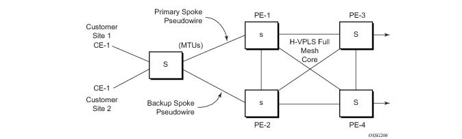
When two or more meshed VPLS instances are interconnected by redundant spoke SDPs (as shown in Figure 10), a loop in the topology results. In order to remove such a loop from the topology, Spanning Tree Protocol (STP) can be run over the SDPs (links) which form the loop such that one of the SDPs is blocked. As running STP in each and every VPLS in this topology is not efficient, the node includes functionality which can associate a number of VPLSes to a single STP instance running over the redundant SDPs. Node redundancy is thus achieved by running STP in one VPLS, and applying the conclusions of this STP to the other VPLS services. The VPLS instance running STP is referred to as the “management VPLS” or mVPLS.
In the case of a failure of the active node, STP on the management VPLS in the standby node will change the link states from disabled to active. The standby node will then broadcast a MAC flush LDP control message in each of the protected VPLS instances, so that the address of the newly active node can be re-learned by all PEs in the VPLS.
It is possible to configure two management VPLS services, where both VPLS services have different active spokes (this is achieved by changing the path-cost in STP). By associating different user VPLSes with the two management VPLS services, load balancing across the spokes can be achieved.
Figure 10: HVPLS with Spoke Redundancy
 
Spoke SDP Based Redundant Access
This feature provides the ability to have a node deployed as MTUs (Multi-Tenant Unit Switches) to be multi-homed for VPLS to multiple routers deployed as PEs without requiring the use of mVPLS.
In the configuration example displayed in Figure 10, the MTUs have spoke SDPs to two PEs devices. One is designated as the primary and one as the secondary spoke SDP. This is based on a precedence value associated with each spoke.
The secondary spoke is in a blocking state (both on receive and transmit) as long as the primary spoke is available. When the primary spoke becomes unavailable (due to link failure, PEs failure, etc.), the MTU immediately switches traffic to the backup spoke and starts receiving traffic from the standby spoke. Optional revertive operation (with configurable switch-back delay) is supported. Forced manual switchover is also supported.
To speed up the convergence time during a switchover, MAC flush is configured. The MTUs generates a MAC flush message over the newly unblocked spoke when a spoke change occurs. As a result, the PEs receiving the MAC flush will flush all MACs associated with the impacted VPLS service instance and forward the MAC flush to the other PEs in the VPLS network if “propagate-mac-flush” is enabled.
 
Inter-Domain VPLS Resiliency Using Multi-Chassis Endpoints
Inter-domain VPLS refers to a VPLS deployment where sites may be located in different domains. An example of inter-domain deployment can be where different Metro domains are interconnected over a Wide Area Network (Metro1-WAN-Metro2) or where sites are located in different autonomous systems (AS1-ASBRs-AS2).
Multi-chassis endpoint (MC-EP) provides an alternate solution that does not require RSTP at the gateway VPLS PEs while still using pseudowires to interconnect the VPLS instances located in the two domains. It is supported in both VPLS and PBB-VPLS on the B-VPLS side.
MC-EP expands the single chassis endpoint based on active-standby pseudowires for VPLS shown in Figure 11.
Figure 11: HVPLS Resiliency Based on AS Pseudowires
The active-standby pseudowire solution is appropriate for the scenario when only one VPLS PE (MTU-s) needs to be dual-homed to two core PEs (PE1 and PE2). When multiple VPLS domains need to be interconnected the above solution provides a single point of failure at the MTU-s. The example depicted in Figure 12 can be used.
Figure 12: Multi-Chassis Pseudowire Endpoint for VPLS
The two gateway pairs, PE3-PE3and PE1-PE2, are interconnected using a full mesh of four pseudowires out of which only one pseudowire is active at any point in time.
The concept of pseudowire endpoint for VPLS provides multi-chassis resiliency controlled by the MC-EP pair, PE3-PE3 in this example. This scenario, referred to as multi-chassis pseudowire endpoint for VPLS, provides a way to group pseudowires distributed between PE3 and PE3 chassis in a virtual endpoint that can be mapped to a VPLS instance.
The MC-EP inter-chassis protocol is used to ensure configuration and status synchronization of the pseudowires that belong to the same MC-EP group on PE3 and PE3. Based on the information received from the peer shelf and the local configuration the master shelf will make a decision on which pseudowire will become active.
The MC-EP solution is built around the following components:
 
Fast Detection of Peer Failure using BFD
Although the MC-EP protocol has its own keep-alive mechanisms, sharing a common mechanism for failure detection with other protocols (for example, BGP, RSVP-TE) scales better. MC-EP can be configured to use the centralized BFD mechanism.
Similar as other protocols, MC-EP will register with BFD if the bfd-enable command is active under the config>redundancy>multi-chassis>peer>mc-ep context. As soon as the MC-EP application is activated using no shutdown, it tries to open a new BFD session or register automatically with an existing one. The source-ip configuration under redundancy multi-chassis peer-ip is used to determine the local interface while the peer-ip is used as the destination IP for the BFD session. After MC-EP registers with an active BFD session, it will use it for fast detection of MC-EP peer failure. If BFD registration or BFD initialization fails, the MC-EP will keep using its own keep-alive mechanism and it will send a trap to the NMS signaling the failure to register with/open BFD session.
In order to minimize operational mistakes and wrong peer interpretation for the loss of BFD session, the following additional rules are enforced when the MC-EP is registering with a certain BFD session:
The no bfd-enable command in the config>redundancy>multi-chassis>peer>mc-ep context – this is the recommended procedure.
The shutdown command in the config>redundancy>multi-chassis>peer>mc-ep or from under config>redundancy>multi-chassis>peer contexts.
MC-EP keep-alives are still exchanged for the following reasons:
If MC-EP de-registers with BFD using the “no bfd-enable” command, the following processing steps occur:
Traps are sent when the status of the monitoring of the MC-EP session through BFD changes in the following instances:
 
MC-EP Passive Mode
The MC-EP mechanisms are built to minimize the possibility of loops. It is possible that human error could create loops through the VPLS service. One way to prevent loops is to enable the MAC move feature in the gateway PEs (PE3, PE3', PE1 and PE2).
An MC-EP passive mode can also be used on the second PE pair, PE1 and PE2, as a second layer of protection to prevent any loops from occurring if the operator introduces operational errors on the MC-EP PE3, PE3 pair.
Figure 13: MC-EP in Passive Mode
When in passive mode, the MC-EP peers stay dormant as long as one active pseudowire is signaled from the remote end. If more than one pseudowire belonging to the passive MC-EP becomes active, then the PE1 and PE2 pair applies the MC-EP selection algorithm to select the best choice and blocks all others. No signaling is sent to the remote pair to avoid flip-flop behavior. A trap is generated each time MC-EP in passive mode activates. Every occurrence of this kind of trap should be analyzed by the operator as it is an indication of possible mis-configuration on the remote (active) MC-EP peering.
In order for the MC-EP passive mode to work, the pseudowire status signaling for active/standby pseudowires should be enabled. This involves the following CLI configurations:
For the remote MC-EP PE3, PE3 pair:
config>service>vpls>endpoint# no suppress-standby-signaling
When MC-EP passive mode is enabled on the PE1 and PE2 pair the following command is always enabled internally, regardless of the actual configuration:
config>service>vpls>endpoint no ignore-standby-signaling
 
Support for Single Chassis Endpoint Mechanisms
In cases of SC-EP, there is consistency check to ensure that the configuration of the member pseudowires is the same. For example, mac-pining, mac-limit and ignore standby signaling must be the same. In the MC-EP case, there is no consistency check between the member endpoints located on different chassis. The operator must verify carefully the configuration of the two endpoints to ensure consistency.
The following rules apply for suppress-standby-signaling and ignore-standby parameters:
For MC-EP configured in passive mode, the following settings will be used, regardless of previous configuration: suppress-standby-sig and no ignore-standby-sig. It is expected that when passive mode is used at one side that the regular MC-EP side will activate signaling with no suppress-stdby-sig.
This section describes also how the main mechanisms used for single chassis endpoint are adapted for the MC-EP solution.
 
MAC Flush Support in MC-EP
In an MC-EP scenario, failure of a pseudowire or gateway PE will determine activation of one of the next best pseudowire in the MC-EP group. This section describes the MAC flush procedures that can be applied to ensure black-hole avoidance.
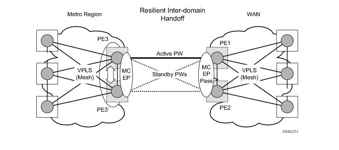
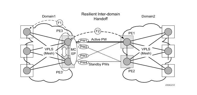
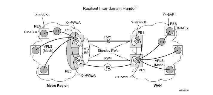
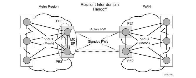
Figure 14 depicts a pair of PE gateways (PE3 and PE3) running MC-EP towards PE1 and PE2 where F1 and F2 are used to indicate the possible direction of the MAC flush signaled using T-LDP MAC withdraw message. PE1 and PE2 can only use regular VPLS pseudowires and do not have to use a MC-EP or a regular pseudowire endpoint.
Figure 14: MAC Flush in the MC-EP Solution
Regular MAC flush behavior will apply for the LDP MAC withdraw sent over the T-LDP Sessions associated with the active pseudowire in the MC-EP, for example PE3 to PE1. That is for any TCN events or failures associated with SAPs or pseudowires not associated with the MC-EP.
The following MAC flush behaviors apply to changes in the MC-EP pseudowire selection:
PE3 must be configured with send-flush-on-failure to send a T-LDP “flush-all-from-me” message towards VPLS mesh in the F1 direction.
PE3 sends a T-LDP flush-all-but-mine message towards PE2 in the F2 direction which is propagated by PE2 in the local VPLS mesh. Note that when MC-EP is in passive mode and the first spoke becomes active, a no mac flush-all-but-mine message will be generated.
 
Block-on-Mesh-Failure Support in MC-EP Scenario
The following rules describe how the block-mesh-on-failure must be ported to the MC-EP solution (see Figure 14):
The default is no block-on-mesh-failure to allow for easy migration from previous releases.
For a spoke SDP to be added under an endpoint, the setting for its block-on-mesh-failure parameter must be in sync with the endpoint parameter.
After the spoke SDP is added to an endpoint, the configuration of its block-on-mesh-failure parameter is disabled. A change in endpoint configuration for the block-on-mesh-failure parameter is propagated to the individual spoke SDP configuration.
Prior to Release 7.0, the block-on-mesh-failure command could not be enabled under config>service>vpls>endpoint context. In order for a spoke SDP to be added to an (single-chassis) endpoint, its block-on-mesh-failure had to be disabled (config>service> vpls>spoke-sdp>no block-on-mesh-failure). Then, the configuration of block-on-mesh-failure under a spoke SDP is blocked.
If block-on-mesh-failure is enabled on PE1 and PE2, these PEs will signal pseudowire standby status toward the MC-EP PE pair. PE3 and PE3 should consider the pseudowire status signaling from remote PE1 and PE2 when making the selection of the active pseudowire.
 
Support for Force Spoke SDP in MC-EP
In a regular (single chassis) endpoint scenario, the following command can be used to force a specific SDP binding (pseudowire) to become active:
tools perform service id service-id endpoint endpoint-name force
In the MC-EP case, this command has a similar effect when there is a single forced SDP binding in an MC-EP. The forced SDP binding (pseudowire) will be elected as active.
However, when the command is run at the same time as both MC-EP PEs, when the endpoints belong to the same mc-endpoint, the regular MC-EP selection algorithm (for example, the operational status -> precedence value) will be applied to determine the winner.
 
Revertive Behavior for Primary Pseudowire(s) in a MC-EP
For a single-chassis endpoint a revert-time command is provided under the VPLS endpoint. Refer to the VPLS Services Command Reference for syntax and command usage information.
In a regular endpoint the revert-time setting affects just the pseudowire defined as primary (precedence 0). For a failure of the primary pseudowire followed by restoration the revert-timer is started. After it expires the primary pseudowire takes the active role in the endpoint. This behavior does not apply for the case when both pseudowires are defined as secondary: i.e. if the active secondary pseudowire fails and is restored it will stay in standby until a configuration change or a force command occurs.
In the MC-EP case the revertive behavior is supported for pseudowire defined as primary (precedence 0). The following rules apply:
 
Using B-VPLS for Increased Scalability and Reduced Convergence Times
The PBB-VPLS solution can be used to improve scalability of the solution and to reduce convergence time. If PBB-VPLS is deployed starting at the edge PEs, the gateway PEs will contain only BVPLS instances. The MC-EP procedures described for regular VPLS apply.
PBB-VPLS can be also enabled just on the gateway MC-EP PEs as depicted in Figure 15 below.
Figure 15: MC-EP with B-VPLS
Multiple I-VPLS instances may be used to represent in the gateway PEs the customer VPLS instances using PBB-VPLS M:1 model described in the PBB section. A backbone VPLS (B-VPLS) is used in this example to administer the resiliency for all customer VPLS instances at the domain borders. Just one MC-EP is required to be configured in the B-VPLS to address 100s or even 1000s of customers VPLS instances. If load balancing is required, multiple B-VPLS instances may be used to ensure even distribution of the customers across all the pseudowires interconnecting the two domains. In this example, four B-VPLS will be able to loadshare the customers across all four possible pseudowire paths.
The use of MC-EP with B-VPLS is strictly limited to cases where VPLS mesh exists on both sides of a B-VPLS. For example, active/standby pseudowires resiliency in the I-VPLS context where PE3, PE3’ are PErs cannot be used because there is no way to synchronize the active/standby selection between the two domains.
For a similar reason, MC-LAG resiliency in the I-VPLS context on the gateway PEs participating in the MC-EP (PE3, PE3) should not be used.
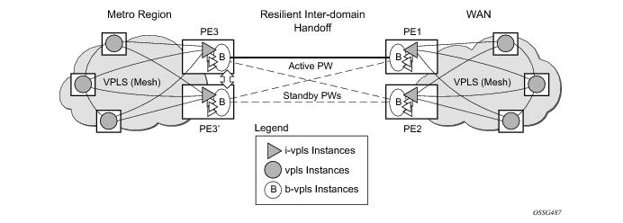
Note that for the PBB topology described in Figure 15, block-on-mesh-failure in the I-VPLS domain will not have any effect on the B-VPLS MC-EP side. That is because mesh failure in one I-VPLS should not affect other I-VPLS sharing the same B-VPLS.
MAC Flush Additions for PBB VPLS
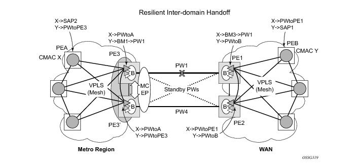
The scenario depicted in Figure 16 is used to define the blackholing problem in PBB-VPLS using MC-EP.
Figure 16: MC-EP with B-VPLS Failure Scenario
In topology displayed in Figure 16, PE A and PE B are regular VPLS PEs participating in the VPLS mesh deployed in the metro and respectively WAN region. As the traffic flows between CEs with CMAC X and CMAC Y, the FIB entries in blue are installed. A failure of the active PW1 will result in the activation of PW4 between PE3 and PE2 in this example. An LDP flush-all-but-mine will be sent from PE3 to PE2 to clear the BVPLS FIBs. The traffic between CMAC X and CMAC Y will be blackholed as long as the entries from the VPLS and I-VPLS FIBs along the path are not removed. This may take as long as 300 seconds, the usual aging timer used for MAC entries in a VPLS FIB.
A MAC flush is required in the I-VPLS space from PBB PEs to PEA and PEB to avoid blackholing in the regular VPLS space.
In the case of a regular VPLS the following procedure is used:
For consistency, a similar procedure is used for the BVPLS case as depicted in Figure 17.
Figure 17: MC-EP with B-VPLS Mac Flush Solution
In this example, the MC-EP activates B-VPLS PW4 because of either a link/node failure or because of an MC-EP selection re-run that affected the previously active PW1. As a result, the endpoint on PE3 containing PW1 goes down.
The following steps apply:
The following command enables this behavior on a per I-VPLS basis:
configure>service>vpls ivpls>propagate-mac-flush-from-bvpls
Other failure scenarios are addressed using the same or a subset of the above steps:
Note that for an SC/MC endpoint configured in a BVPLS, failure/de-activation of the active pseudowire member always generates a local MAC flush of all the BMAC associated with the pseudowire. It never generates a MAC move to the newly active pseudowire even if the endpoint stays up. That is because in SC-EP/MC-EP topology, the remote PE might be the terminating PBB PE and may not be able to reach the BMAC of the other remote PE. In other words, connectivity between them exists only over the regular VPLS Mesh.
For the same reasons, it is recommended that static BMAC not be used on SC/MC endpoints.
 
VPLS Access Redundancy
A second application of hierarchical VPLS is using MTUs that are not MPLS-enabled which must have Ethernet links to the closest PE node. To protect against failure of the PE node, an MTU can be dual-homed and have two SAPs on two PE nodes.
There are several mechanisms that can be used to resolve a loop in an access circuit, however from operation perspective they can be subdivided into two groups:
 
STP-Based Redundant Access to VPLS
Figure 18: Dual Homed MTU-s in Two-Tier Hierarchy H-VPLS
In configuration shown in Figure 18, STP is activated on the MTU and two PEs in order to resolve a potential loop.Note that STP only needs to run in a single VPLS instance, and the results of the STP calculations are applied to all VPLSes on the link.
In this configuration the scope of STP domain is limited to MTU and PEs, while any topology change needs to be propagated in the whole VPLS domain including mesh SDPs. This is done by using so called “MAC-flush” messages defined by RFC 4762. In case of STP as an loop resolution mechanism, every TCN (Topology Change Notification) received in a context of STP instance is translated into LDP- MAC address withdrawal message (also referred to as MAC-flush message) requesting to clear all FDB entries, but the ones learned from originating PE. Such messages are sent to all PE peers connected through SDPs (mesh and spoke) in the context of VPLS service(s) which are managed by the given STP instance.
 
Redundant Access to VPLS Without STP
The Alcatel-Lucent implementation also alternative methods for providing a redundant access to LAYER 2 services, such as MC-LAG, MC-APS or MC-RING. Also in this case, the topology change event needs to be propagated into VPLS topology in order to provide fast convergence.
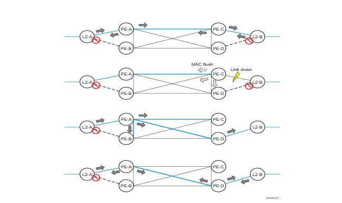
Figure 10 illustrates a dual-homed connection to VPLS service (PE-A, PE-B, PE-C, PE-D) and operation in case of link failure (between PE-C and L2-B). Upon detection of a link failure PE-C will send MAC-Address-Withdraw messages, which will indicate to all LDP peers that they should flush all MAC addresses learned from PE-C. This will lead that to a broadcasting of packets addressing affected hosts and re-learning process in case an alternative route exists.
Note that the message described here is different than the message described in previous section and in RFC 4762, Virtual Private LAN Services Using LDP Signaling. The difference is in the interpretation and action performed in the receiving PE. According to the standard definition, upon receipt of a MAC withdraw message, all MAC addresses, except the ones learned from the source PE, are flushed,
This section specifies that all MAC addresses learned from the source are flushed. This message has been implemented as an LDP address message with vendor-specific type, length, value (TLV), and is called the flush-mine message.
The advantage of this approach (as compared to RSTP based methods) is that only MAC-affected addresses are flushed and not the full forwarding database. While this method does not provide a mechanism to secure alternative loop-free topology, the convergence time is dependent on the speed of the given CE device will open alternative link (L2-B switch in Figure 57) as well as on the speed PE routers will flush their FDB.
In addition, this mechanism is effective only if PE and CE are directly connected (no hub or bridge) as it reacts to physical failure of the link.
 
Object Grouping and State Monitoring
This feature introduces a generic operational group object which associates different service endpoints (pseudowires, SAPs, IP interfaces) located in the same or in different service instances.
The operational group status is derived from the status of the individual components using certain rules specific to the application using the concept. A number of other service entities, the monitoring objects, can be configured to monitor the operational group status and to perform certain actions as a result of status transitions. For example, if the operational group goes down, the monitoring objects will be brought down.
 
VPLS ApplicabilityBlock on VPLS a Failure
This concept is used in VPLS to enhance the existing BGP MH solution by providing a block-on-group failure function similar with the Block-on-mesh failure feature implemented in the past for LDP VPLS mesh. On the PE selected as the Designated Forwarder (DF), if the rest of the VPLS endpoints fail (pseudowire spoke(s)/pseudowire mesh and/or SAP(s)), there is no path forward for the frames sent to the MH site selected as DF. The status of the VPLS endpoints, other than the MH site, is reflected by bringing down/up the object(s) associated with the MH site.
Support for the feature is provided initially in VPLS and BVPLS instance types for LDP VPLS with or without BGP-AD and for BGP VPLS. The following objects may be placed as components of an operational group: BGP VPLS pseudowires, SAPs, spoke-pseudowire, BGP-AD pseudowires. The following objects are supported as monitoring objects: BGP MH site, Individual SAP, spoke-pseudowire.
The following rules apply:
Operational group feature may co-exist in parallel with the block-on-mesh feature as long as they are running in different VPLS instances
 
 
There are two steps involved in enabling the block on group failure in a VPLS scenario:
1.
2.
Associate other existing objects (clients) with the oper-group using the monitor-group CLI command; its forwarding state will be derived from the related operational group state.
The status of the operational group (oper-group) is dictated by the status of one or more members according to the following rule:
For BGP-AD or BGP VPLS pseudowire(s) associated with the oper-group (under the config>service-vpls>bgp>pw-template-binding context), the status of the oper-group is down as long as the pseudowire members are not instantiated (auto-discovered and signaled).
A simple configuration example is described for the case of a BGP VPLS mesh used to interconnect different customer location. If we assume a customer edge (CE) device is dual-homed to two PEs using BGP MH the following configuration steps apply:
The oper-group bgp-vpls-mesh is created
The BGP VPLS mesh is added to the bgp-vpls-mesh group through the pseudowire template used to create the BGP VPLS mesh
The BGP MH site defined for the access endpoint is associated with the bgp-vpls-mesh group; its status from now on will be influenced by the status of the BGP VPLS mesh
A simple configuration example follows:
service>oper-group bgp-vpls-mesh-1 create
service>vpls>bgp>pw-template-binding> oper-group bgp-vpls-mesh-1
service>vpls>site> monitor-group bgp-vpls-mesh-1


MAC Flush Message Processing
The previous sections described operation principle of several redundancy mechanisms available in context of VPLS service. All of them rely on MAC flush message as a tool to propagate topology change in a context of the given VPLS. This section aims to summarize basic rules for generation and processing of these messages.
As described on respective sections, the 7750 SR supports two types of MAC flush message, flush-all-but-mine and flush-mine. The main difference between these messages is the type of action they signal. Flush-all-but-mine requests clearing of all FDB entries which were learned from all other LDP peers except the originating PE. This type is also defined by RFC 4762 as an LDP MAC address withdrawal with an empty MAC address list.
Flush-all-mine message requests clearing all FDB entries learned from originating PE. This means that this message has exactly other effect then flush-all-but-mine message. This type is not included in RFC 4762 definition and it is implemented using vendor specific TLV.
The advantages and disadvantages of the individual types should be apparent from examples in the previous section. The description here focuses on summarizing actions taken on reception and conditions individual messages are generated.
Upon reception of MAC flush messages (regardless the type) SR-Series PE will take following actions:
The flush-all-but-mine message is generated under following conditions:
 
The flush-mine message is generated under following conditions:
 
Dual Homing to a VPLS Service
Figure 19: Dual Homed CE Connection to VPLS
Figure 19 illustrates a dual-homed connection to VPLS service (PE-A, PE-B, PE-C, PE-D) and operation in case of link failure (between PE-C and L2-B). Upon detection of a link failure PE-C will send MAC-Address-Withdraw messages, which will indicate to all LDP peers that they should flush all MAC addresses learned from PE-C. This will lead that to a broadcasting of packets addressing affected hosts and re-learning process in case an alternative route exists.
Note that the message described here is different than the message described in draft-ietf-l2vpn-vpls-ldp-xx.txt, Virtual Private LAN Services over MPLS. The difference is in the interpretation and action performed in the receiving PE. According the draft definition, upon receipt of a MAC-withdraw message, all MAC addresses, except the ones learned from the source PE, are flushed, This section specifies that all MAC addresses learned from the source are flushed. This message has been implemented as an LDP address message with vendor-specific type, length, value (TLV), and is called the flush-all-from-ME message.
The draft definition message is currently used in management VPLS which is using RSTP for recovering from failures in Layer 2 topologies. The mechanism described in this document represent an alternative solution.
The advantage of this approach (as compared to RSTP based methods) is that only MAC-affected addresses are flushed and not the full forwarding database. While this method does not provide a mechanism to secure alternative loop-free topology, the convergence time is dependent on the speed of the given CE device will open alternative link (L2-B switch in Figure 19) as well as on the speed PE routers will flush their FDB.
In addition, this mechanism is effective only if PE and CE are directly connected (no hub or bridge) as it reacts to physical failure of the link.
 
MC-Ring and VPLS
The use of multi-chassis ring control in a combination with the plain VPLS SAP is supported FDB in individual ring nodes in case of the link (or ring node) failure cannot be cleared.
This combination is not easily blocked in the CLI. If configured, the combination may be functional but the switchover times will be proportional to MAC aging in individual ring nodes and/or to relearning rate due to downstream traffic.
Redundant plain VPLS access in ring configurations, therefore, exclude corresponding SAPs from the multi-chassis ring operation. Configurations such as mVPLS can be applied.
 
ACL Next-Hop for VPLS
Figure 20: Application 1 Diagram
The ACL next-hop for VPLS feature enables an ACL that has a forward next-hop SAP or SDP action specified to be used in a VPLS service to direct traffic with specific match criteria to a SAP or SDP. This allows traffic destined to the same gateway to be split and forwarded differently based on the ACL.
Policy routing is a popular tool used to direct traffic in Layer 3 networks. As Layer 2 VPNs become more popular, especially in network aggregation, policy forwarding is required. Many providers are using methods such as DPI servers, transparent firewalls or Intrusion Detection/Prevention Systems (IDS/IPS). Since these devices are bandwidth limited providers want to limit traffic forwarded through them. A mechanism is required to direct some traffic coming from a SAP to the DPI without learning and other traffic coming from the same SAP directly to the gateway uplink based learning. This feature will allow the provider to create a filter that will forward packets to a specific SAP or SDP. The packets are then forwarded to the destination SAP regardless of learned destination or lack thereof. The SAP can either terminate a Layer 2 firewall, deep packet inspection (DPI) directly or may be configured to be part of a cross connect bridge into another service. This will be useful when running the DPI remotely using VLLs. If an SDP is used the provider can terminate it in a remote VPLS or VLL service where the firewall is connected. The filter can be configured under a SAP or SDP in a VPLS service. All packets (unicast, multicast, broadcast and unknown) can be delivered to the destination SAP/SDP.
The filter may be associated SAPs/SDPs belonging to a VPLS service only if all actions in the ACL forward to SAPs/SDPs that are within the context of that VPLS. Other services do not support this feature. An ACL that contains this feature is allowed but the system will drop any packet that matches an entry with this action.
 
SDP Statistics for VPLS and VLL Services
Figure 21: SDP Statistics for VPLS and VLL Services
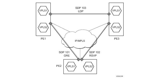
The simple three-node network described in Figure 21 shows two MPLS SDPs and one GRE SDP defined between the nodes. These SDPs connect VPLS1 and VPLS2 instances that are defined in the three nodes. With this feature the operator will have local CLI based as well as SNMP based statistics collection for each VC used in the SDPs. This will allow for traffic management of tunnel usage by the different services and with aggregation the total tunnel usage.
SDP statistics allow providers to bill customers on a per-SDP per-byte basis. This destination- based billing model is can be used by providers with a variety of circuit types and have different costs associated with the circuits. An accounting file allows the collection of statistics in a bulk manner.
 
RADIUS Auto-Discovery
 
Auto SDPs and Auto SDP Bindings
When a VPLS service is created and the radius-discovery command is enabled, manual configuration of SDPs is not required. The far-end SDP is discovered by RADIUS and an auto-SDP will be created for each far-end PE. An auto-SDP binding will be created for the service (the SDP binding is on a per service basis). The auto-SDP can be used for other VPLS service instances between the pair of PEs. If a manual SDP binding is created for the service, it will be preferred to the auto-SDP binding to allow override.
An auto-SDP is created by a PE router automatically with information provided by RADIUS discovery. The binding, auto-SDP binding is created automatically for an auto-SDP. An auto-SDP can be GRE based or LDP based. The default is GRE.
An SNMP trap is generated to inform the NMS about the creation of an auto-SDP or auto-SDP binding. Auto-SDPs and auto-SDP bindings are not saved in the router configuration file. Auto-SDPs cannot be manually configured nor modified.
 
Manual SDPs and Manual SDP Bindings
“Manual” SDPs can be used with RADIUS discovery. Manual SDPs take precedence over auto SDPs.
If a manual SDP is available, it should be used to create the auto SDP binding; otherwise, the PE router creates auto SDPs and auto SDP bindings. If there are multiple SDPs available for a remote PE router, the SDP with the highest SDP ID should be used.
If a manual SDP was provisioned after the RADIUS discovery process, the admin>radius-discovery>force-discover command should be executed in order to use the new manual SDPs.
Users cannot remove a manual SDP if there is an auto SDP binding associated with the manual SDP. However, manual SDP bindings and RADIUS discovery are mutually exclusive. If a manual SDP binding was already provisioned for a service, RADIUS discovery cannot be enabled for the service. If RADIUS discovery was already enabled for a service, manual SDP bindings cannot be provisioned for the service.
 
Discovery Procedures
A PE router issues an access-request to the RADIUS server using the configured VPN as the user-name and configured password. The service type of the access request is L2VPN.
The RADIUS server authenticates the PE router. If authentication is successful, it responds with an access-accept which includes a list of IP addresses of the PE routers. Optional information such as vc-type and SDP could be included. If authentication fails, an access-reject message is returned. The access-accept response has a session-timeout attribute in which a PE router needs to issue a new access-request before the access-accept times out.
 
Auto SDPs and SDP-Bindings Creation
After the discovery of all other PE routers, the PE router checks if it has valid auto SDP bindings for remote PE routers. Manual SDPs always take precedence over auto SDPs. If there was a manual SDP available, it is used to create the auto SDP binding; otherwise, the PE router creates auto SDPs and auto SDP bindings. If there were multiple SDPs available for a PE router, the SDP with the smallest SDP ID is used.
What auto-SDP to create, LDP or GRE, depends on the RADIUS configuration, default is GRE.
When an auto SDP is created for a remote PE router and there is no targeted LDP session to the PE router, a targeted LDP session is automatically created.
 
Pseudo-Wire Setup
The PE routers use “AII” as the VC-ID (pseudowire ID) to signal pseudowires to each other by targeted LDP.
 
RADIUS Server Polling
A PE router should periodically query the RADIUS server to make sure its L2VPN membership information is up-to-date. The polling interval is configurable by CLI.
Any change to the VPN membership (such as adding or removing a PE) takes effect at the next polling.
 
Removing RADIUS Discovery
The VPLS service must be shut down in order to disable or remove RADIUS discovery from a VPLS service.
When RADIUS discovery is disabled for a VPLS service, auto SDPs and auto SDP-bindings for that VPLS are removed.
 
Remove a PE from VPLS
When a PE is removed from a VPLS service, the RADIUS server must be updated manually to remove the PE from the membership database.
 
BGP Auto-Discovery for LDP VPLS
BGP Auto Discovery (BGP AD) for LDP VPLS is a framework for automatically discovering the endpoints of a Layer 2 VPN offering an operational model similar to that of an IP VPN. This allows carriers to leverage existing network elements and functions, including but not limited to, route reflectors and BGP policies to control the VPLS topology.
BGP AD is an excellent complement to an already established and well deployed Layer 2 VPN signaling mechanism target LDP providing one touch provisioning for LDP VPLS where all the related PEs are discovered automatically. The service provider may make use of existing BGP policies to regulate the exchanges between PEs in the same, or in different, autonomous system (AS) domains. The addition of BGP AD procedures does not require carriers to uproot their existing VPLS deployments and to change the signaling protocol.
 
BGP AD Overview
The BGP protocol establishes neighbor relationships between configured peers. An open message is sent after the completion of the three-way TCP handshake. This open message contains information about the BGP peer sending the message. This message contains Autonomous System Number (ASN), BGP version, timer information and operational parameters, including capabilities. The capabilities of a peer are exchanged using two numerical values: the Address Family Identifier (AFI) and Subsequent Address Family Identifier (SAFI). These numbers are allocated by the Internet Assigned Numbers Authority (IANA). BGP AD uses AFI 65 (L2VPN) and SAFI 25 (BGP VPLS). The complete list of allocations may be found at: http://www.iana.org/assignments/address-family-numbers and SAFI http://www.iana.org/assignments/safi-namespace.
 
Information Model
Following the establishment of the peer relationship, the discovery process begins as soon as a new VPLS service instance is provisioned on the PE.
Two VPLS identifiers are used to indicate the VPLS membership and the individual VPLS instance:
In order to advertise this information, BGP AD employs a simplified version of the BGP VPLS NLRI where just the RD and the next 4 bytes are used to identify the VPLS instance. There is no need for Label Block and Label Size fields as T-LDP will take care of signaling the service labels later on.
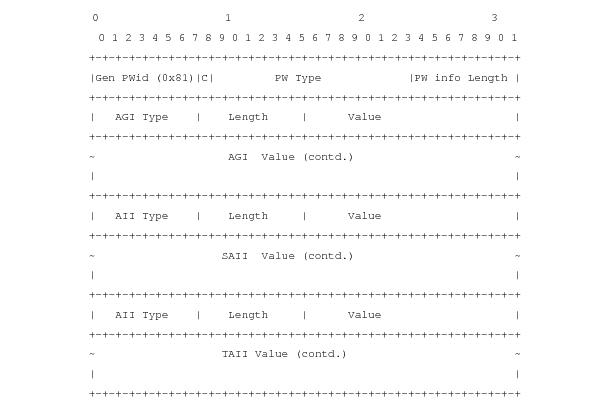
The format of the BGP AD NLRI is very similar with the one used for IP VPN as depicted in Figure 22. The system IP may be used for the last 4 bytes of the VSI ID further simplifying the addressing and the provisioning process.
Figure 22: BGP AD NLRI versus IP VPN NLRI
Network Layer Reachability Information (NLRI) is exchanged between BGP peers indicating how to reach prefixes. The NLRI is used in the Layer 2 VPN case to tell PE peers how to reach the VSI rather than specific prefixes. The advertisement includes the BGP next hop and a route target (RT). The BGP next hop indicates the VSI location and is used in the next step to determine which signaling session is used for pseudowire signaling. The RT, also coded as an extended community, can be used to build a VPLS full mesh or a HVPLS hierarchy through the use of BGP import/export policies.
BGP is only used to discover VPN endpoints and the corresponding far end PEs. It is not used to signal the pseudowire labels. This task remains the responsibility of targeted-LDP (T-LDP).
 
FEC Element for T-LDP Signaling
Two LDP FEC elements are defined in RFC 4447, PW Setup & Maintenance Using LDP. The original pseudowire-ID FEC element 128 (0x80) employs a 32-bit field to identify the virtual circuit ID and it was used extensively in the initial VPWS and VPLS deployments. The simple format is easy to understand but it does not provide the required information model for BGP auto-discovery function. In order to support BGP AD and other new applications a new Layer 2 FEC element, the generalized FEC (0x81) is required.
The generalized pseudowire-ID FEC element has been designed for auto discovery applications. It provides a field, the address group identifier (AGI), that is used to signal the membership information from the VPLS-ID. Separate address fields are provided for the source and target address associated with the VPLS endpoints called the Source Attachment Individual Identifier (SAII) and respectively, Target Attachment Individual Identifier (TAII). These fields carry the VSI ID values for the two instances that are to be connected through the signaled pseudowire.
The detailed format for FEC 129 is depicted in Figure 23.
Figure 23: Generalized Pseudowire-ID FEC Element
Each of the FEC fields are designed as a sub-TLV equipped with its own type and length providing support for new applications. To accommodate the BGP AD information model the following FEC formats are used:
 
BGP-AD and Target LDP (T-LDP) Interaction
BGP is responsible for discovering the location of VSIs that share the same VPLS membership. LDP protocol is responsible for setting up the pseudowire infrastructure between the related VSIs by exchanging service specific labels between them.
Once the local VPLS information is provisioned in the local PE, the related PEs participating in the same VPLS are identified through BGP AD exchanges. A list of far-end PEs is generated and will trigger the creation, if required, of the necessary T-LDP sessions to these PEs and the exchange of the service specific VPN labels. The steps for the BGP AD discovery process and LDP session establishment and label exchange are shown in Figure 24.
Figure 24: BGP-AD and T-LDP Interaction
Key:
1.
2.
3.
4.
5.
6.
7.
8.
9.
10.
 
SDP Usage
Service Access Points (SAP) are linked to transport tunnels using Service Distribution Points (SDP). The service architecture allows services to be abstracted from the transport network.
MPLS transport tunnels are signaled using the Resource Reservation Protocol (RSVP-TE) or by the Label Distribution Protocol (LDP). The capability to automatically create an SDP only exists for LDP based transport tunnels. Using a manually provisioned SDP is available for both RSVP-TE and LDP transport tunnels. Refer to the appropriate OS MPLS Guide for more information about MPLS, LDP, and RSVP.
 
Automatic Creation of SDPs
When BGP AD is used for LDP VPLS and LDP is used as the transport tunnel there is no requirement to manually create an SDP. The LDP SDP can be automatically instantiated using the information advertised by BGP AD. This simplifies the configuration on the service node.
Enabling LDP on the IP interfaces connecting all nodes between the ingress and the egress builds transport tunnels based on the best IGP path. LDP bindings are automatically built and stored in the hardware. These entries contain an MPLS label pointing to the best next hop along the best path toward the destination.
When two endpoints need to connect and no SDP exists, a new SDP will automatically be constructed. New services added between two endpoints that already have an automatically created SDP will be immediately used. No new SDP will be constructed. The far-end information is gleaned from the BGP next hop information in the NLRI. When services are withdrawn with a BGP_Unreach_NLRI, the automatically established SDP will remain up as long as at least one service is connected between those endpoints. An automatically created SDP will be removed and the resources released when the only or last service is removed.
 
Manually Provisioned SDP
The carrier is required to manually provision the SDP if they create transport tunnels using RSVP-TE. Operators have the option to choose a manually configured SDP if they use LDP as the tunnel signaling protocol. The functionality is the same regardless of the signaling protocol.
Creating a BGP AD enabled VPLS service on an ingress node with the manually provisioned SDP option causes the Tunnel Manager to search for an existing SDP that connects to the far-end PE. The far-end IP information is gleaned from the BGP next hop information in the NLRI. If a single SDP exists to that PE, it is used. If no SDP is established between the two endpoints, the service will remain down until a manually configured SDP becomes active.
When multiple SDPs exist between two endpoints, the tunnel manager will select the appropriate SDP. The algorithm will prefer SDPs with the best (lower) metric. Should there be multiple SDPs with equal metrics, the operational state of the SDPs with the best metric will be considered. If the operational state is the same, the SDP with the higher sdp-id will be used. If an SDP with a preferred metric is found with an operational state that is not active, the tunnel manager will flag it as ineligible and restart the algorithm.
 
Automatic Instantiation of Pseudowires (SDP Bindings)
The choice of manual or auto provisioned SDPs has limited impact on the amount of required provisioning. Most of the savings are achieved through the automatic instantiation of the pseudowire infrastructure (SDP bindings). This is achieved for every auto-discovered VSIs through the use of the pseudowire template concept. Each VPLS service that uses BGP AD contains the “pw-template-binding” option defining specific layer 2 VPN parameters. This command references a “pw-template” which defines the pseudowire parameters. The same “pw-template” may be referenced by multiple VPLS services. As a result, changes to these pseudowire templates have to be treated with great care as they may impact many customers at once.
The Alcatel-Lucent implementation provides for safe handling of pseudowire templates. Changes to the pseudowire templates are not automatically propagated. Tools are provided to evaluate and distribute the changes. The following command is used to distribute changes to a “pw-template” at the service level to one or all services that use that template.
PERs-4# tools perform service id 300 eval-pw-template 1 allow-service-impact
If the service ID is omitted, then all services will be updated. The type of change made to the “pw-template” will influence how the service is impacted.
1.
2.
Changing parameters in the vc-type {ether | vlan} command requires LDP to re-signal the labels.
Both of these changes are service affecting. Other changes will not be service affecting.
 
Mixing Statically Configured and Auto-Discovered Pseudowires in a VPLS
The services implementation allows for manually provisioned and auto-discovered pseudowire (SDP bindings) to coexist in the same VPLS instance (for example, both FEC128 and FEC 129 are supported). This allows for gradual introduction of auto discovery into an existing VPLS deployment.
As FEC 128 and 129 represent different addressing schemes, it is important to make sure that only one is used at any point in time between the same two VPLS instances. Otherwise, both pseudowires may become active causing a loop that might adversely impact the correct functioning of the service. It is recommended that FEC128 pseudowire be disabled as soon as the FEC129 addressing scheme is introduced in a portion of the network. Alternatively, RSTP may be used during the migration as a safety mechanism to provide additional protection against operational errors.
 
Resiliency Schemes
The use of BGP AD on the network side, or in the backbone, does not affect the different resiliency schemes Alcatel-Lucent has developed in the access network. This means that both Multi-Chassis Link Aggregation (MC-LAG) and Management-VPLS (M-VPLS) can still be used.
BGP AD may coexist with Hierarchical-VPLS (H-VPLS) resiliency schemes (for example, dual homed MTU-s devices to different PE-rs nodes) using existing methods (M-VPLS and statically configured Active/Standby pseudowire endpoint).
If provisioned SDPs are used by BGP AD, M-VPLS may be employed to provide loop avoidance. However, it is currently not possible to auto-discover active/standby pseudowires and to instantiate the related endpoint.
 
BGP VPLS
The Alcatel-Lucent BGP VPLS solution, compliant with RFC 4761, Virtual Private LAN Service (VPLS) Using BGP for Auto-Discovery and Signaling, is described in this section.
Figure 25: BGP VPLS Solution
Figure 25 depicts the service representation for BGP VPLS mesh. The major BGP VPLS components and the deltas from LDP VPLS with BGP AD are explained below:
 
Pseudowire Signaling Details
The pseudowire is setup using the following NLRI fields:
This BGP update is telling the other PE(s) that accept the RT: “in order to reach me (VE-ID = x) use a pseudowire label of LB + VE-ID – VBO using the BGP NLRI for which VBO =< local VE-ID < VBO + VBS.
Here is an example of how this algorithm works assuming PE1 has VE-ID 7 configured:
Assuming that VE-ID = 10 is configured in another PE4 the following procedure applies:
In addition to the pseudowire label information, the Layer2 Info Extended Community attribute must be included in the BGP Update for BGP VPLS to signal the attributes of all the pseudowires that converge towards the originator VPLS PE.
The format is described below:
+------------------------------------+
| Extended community type (2 octets) |
+------------------------------------+
|  Encaps Type (1 octet)             |
+------------------------------------+
|  Control Flags (1 octet)           |
+------------------------------------+
|  Layer-2 MTU (2 octet)             |
+------------------------------------+
|  Reserved (2 octets)               |
+------------------------------------+
The meaning of the fields:
The detailed format for the Control Flags bit vector is described below:
0 1 2 3 4 5 6 7
+-+-+-+-+-+-+-+-+
|D| MBZ |C|S| (MBZ = MUST Be Zero)
+-+-+-+-+-+-+-+-+
The following bits in the Control Flags are defined:
Here are the events that set the D-bit to 1 to indicate VSI down status in BGP update message sent out from a PE:
The following events do not set the D-bit to 1:
 
Supported VPLS Features
BGP VPLS just added support for a new type of pseudowire signaling based on MP-BGP. It is based on the existing VPLS instance hence it inherited all the existing Ethernet switching functions. Here are some of the most important existing VPLS features ported also to BGP VPLS:
 
BGP VPLS Configuration Procedure
BGP VPLS configuration requires the setup of the MPLS infrastructure and VPLS instance:
The provisioning of the BGP VPLS information is similar with the BGP AD for LDP VPLS procedure:
The BGP VPLS parameters are provisioned at VPLS instance level, once for all SDPs, automatically generating the SDP associations using a procedure similar with the auto-binding in BGP-VPNs/BGP-AD: i.e.
 
Use of Pseudowire Template for BGP VPLS
The pseudowire template concept used for BGP AD is re-used also for BGP VPLS to dynamically instantiate pseudowire (SDP-bindings) and the related SDP (provisioned or automatically instantiated).
On transmission the settings for the L2-Info extended community in the BGP Update are derived from the pseudowire-template attributes. The following rules apply:
On reception the values of the parameters in the L2-Info extended community of the BGP Update are compared with the settings from the corresponding pseudowire-template. The following steps are used to determine the local pseudowire-template:
The tools perform commands can be used similarly as for BGP-AD to force the application of changes in pseudowire-template using the format described below:
tools perform service [id service-id] eval-pw-template policy-id [allow-service-impact]
This command is as follows:
Usage example: assuming the service vpls 100 bgp pw-template-binding 1 import-rt 100:50 was removed, the following command can be used to remove the old pseudowire-bindings:
tools perform service id 100 eval-pw-template 1 allow-service-impact
Including the service id is not mandatory but it is recommended as it will reduce the scope of the command to only the affected service id.
 
BGP Multi-Homing for VPLS
This section describes BGP based procedures for electing a designated forwarder among the set of PEs that are multi-homed to a customer site. Only the local PEs are actively participating in the selection algorithm. The PE(s) remote from the dual homed CE are not required to participate in the designated forwarding election for a remote dual-homed CE.
The main components of the BGP based multi-homing solution for VPLS are:
 
 
Figure 26: BGP Multi-Homing for VPLS
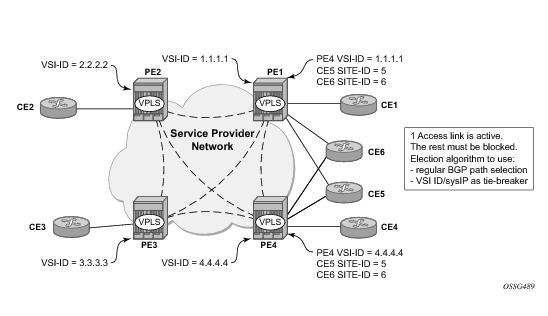
Figure 26 depicts the VPLS using BGP Multi-homing for the case of multi-homed CEs. Although the picture depicts the case of a pseudowire infrastructure signaled with LDP for a LDP VPLS using BGP-AD for discovery, the procedures are identical for BGP VPLS or for a mix of BGP and LDP signaled pseudowires.
 
Information Model and Required Extensions to L2VPN NLRI
VPLS Multi-homing using BGP-MP expands on the BGP AD and BGP VPLS provisioning model. The addressing for the Multi-homed site is still independent from the addressing for the base VSI (VSI-ID or respectively VE-ID). Every multi-homed CE is represented in the VPLS context through a site-id, which is the same on the local PEs. The site-id is unique within the scope of a VPLS. It serves to differentiate between the multi-homed CEs connected to the same VPLS Instance (VSI). For example, in Figure 27, CE5 will be assigned the same site-id on both PE1 and PE4. For the same VPLS instance though, different SITE-IDs are assigned for multi-homed CE5 and CE6: for example, site id 5 is assigned for CE5 and site id 6 is assigned for CE6. The single-homed CEs (CE1, 2, 3 and 4) do not require allocation of a multi-homed site-id. They are associated with the addressing for the base VSI, either VSI-ID or VE-ID.
The new information model required changes to the BGP usage of the NLRI for VPLS. The extended MH NLRI for Multi-Homed VPLS is compared with the BGP AD and BGP VPLS NLRIs in Figure 27.
Figure 27: BGP MH-NLRI for VPLS Multi-Homing
The BGP VPLS NLRI described in RFC 4761 is used to carry a two (2) byte site-ID that identifies the MH Site. The last seven (7) bytes of the BGP VPLS NLRI used to instantiate the pseudowire are not used for BGP-MH and are ZEROed out. This NLRI format translates into the following processing path in the receiving VPLS PE:
The processing procedures described in this section start from the above identification of the BGP Update as not destined for pseudowire signaling.
The RD ensures the NLRIs associated with a certain site-id on different PEs are seen as different by any of the intermediate BGP nodes (RRs) on the path between the multi-homed PEs. In other words, different RDs must be used on the MH PEs every time an RR or an ASBR is involved to guarantee the MH NLRIs reach the PEs involved in VPLS MH.
The L2-Info extended community from RFC 4761 is used in the BGP update for MH NLRI to initiate a MAC flush for blackhole avoidance to indicate the operational and admin status for the MH Site or the DF election status.
After the pseudowire infrastructure between VSIs is built using either RFC 4762, Virtual Private LAN Service (VPLS) Using Label Distribution Protocol (LDP) Signaling, or RFC 4761 procedures or a mix of pseudowire Signaling procedure, on activation of a multi- homed site, an election algorithm must be run on the local and remote PEs to determine which site will be the designated forwarder (DF). The end result is that all the related MH sites in a VPLS will be placed in standby except for the site selected as DF. Alcatel-Lucent BGP-based multi-homing solution uses the DF election procedure described in the IETF working group document draft-ietf-l2vpn-vpls-multihoming. The initial implementation allows the use of BGP Local Preference but does not support VPLS preference.
The implementation allows the use of BGP Local Preference and the received VPLS preference, but does not support setting the VPLS preference to a non-zero value.
 
Supported Services and Multi-Homing Objects
This feature is supported for the following services:
The following access objects can be associated with MH SITE:
 
Blackhole Avoidance
Blackholing refers to the forwarding of frames to a PE that is no longer carrying the designated forwarder. This could happen for traffic from:
Changes in DF election results or MH site status must be detected by all of the above network elements to provide for Blackhole Avoidance.
 
MAC Flush to the Core PEs
Assuming there is a transition of the existing DF to non-DF status. The PE that owns the MH site experiencing this transition will generate a MAC flush-all-from-me (negative MAC flush) towards the related core PEs. Upon reception, the remote PEs will flush all the MACs learned from the MH PE.
MAC flush-all-from-me indication is sent using the following core mechanisms:
 
Indicating non-DF status towards the access PE or CE
For the CEs or access PEs support is provided for indicating the blocking of the MH site using the following procedures:
 
BGP Multi-Homing for VPLS Inter-Domain Resiliency
BGP MH for VPLS can be used to provide resiliency between different VPLS domains. An example of a Multi-Homing topology is depicted in Figure 28.
Figure 28: BGP MH Used in an HVPLS Topology
LDP VPLS domains are interconnected using a core VPLS domain either BGP VPLS or LDP VPLS. The gateway PEs, for example PE2 and PE3, are running BGP multi-homing where one MH site is assigned to each of the pseudowires connecting the access PE, PE7, and PE8 in this example.
Alternatively, one may choose to associate the MH site to multiple access pseudowires using an access SHG. The config>service>vpls>site>failed-threshold command can be used to indicates the number of pseudowire failures that are required for the MH site to be declared down.
 
 
Multicast-Aware VPLS
VPLS is a Layer 2 service, hence, multicast and broadcast frames are normally flooded in a VPLS. Broadcast frames are targeted to all receivers. However, for IP multicast, normally for a multicast group, only some receivers in the VPLS are interested. Flooding to all sites can cause wasted network bandwidth and unnecessary replication on the ingress PE router.
In order to improve this condition, VPLS is IP multicast aware so it forwards IP multicast traffic based on multicast states.
 
PIM Snooping for VPLS
PIM snooping for VPLS allows a VPLS PE router to build multicast states by snooping PIM protocol packets that are sent over the VPLS. The VPLS PE then forwards multicast traffic based on the multicast states. When all receivers in a VPLS are IP multicast routers running PIM, multicast forwarding in the VPLS is efficient when PIM snooping for VPLS is enabled.
Because of PIM join/prune suppression, in order to make PIM snooping operate over VPLS pseudowires, two options are available, plain PIM snooping and PIM proxy. PIM proxy is the default behavior when PIM snooping is enabled for a VPLS.
 
Plain PIM Snooping
In plain PIM snooping configuration, VPLS PE routers only snoop, PIM messages generated on their own. Join/prune suppression must be disabled on CE routers.
When plain PIM snooping is configured, a VPLS PE router detects a condition where join/prune suppression is not disabled on one or multiple CE routers, the PE router should put PIM snooping into PIM proxy state. A trap is generated which reports the condition to the operator and is logged to syslog. If the condition changes, for example, join/prune suppression was disabled on CE routers, the PE reverts to plain PIM snooping state. A trap is generated and is logged to syslog.
 
PIM Proxy
For PIM proxy configurations, VPLS PE routers perform the following:
Join/prune suppression is not required to be disabled on CE routers, but it requires all PEs in the VPLS to have PIM proxy enabled. Otherwise, CEs behind the PE(s) that do not have PIM proxy enabled may not be able to get multicast traffic that they are interested in if they have join/prune suppression enabled.
When PIM proxy is enabled, but a VPLS PE router detects a condition where join/prune suppression is disabled on all CE routers, the PE router put PIM proxy into a plain PIM snooping state to improve efficiency. A trap is generated to report the scenario to the operator and is logged to syslog. If the condition changes, for example, join/prune suppression enabled on a CE router, PIM proxy is placed back into operational state. Again, a trap is generated to report the condition to the operator and is logged to syslog.
 
Multicast Listener Discovery (MLD) Snooping and MAC-Based Multicast Forwarding
VPLS-based transport is a popular architecture as it better handles IPv6 multicast on the transport configurations for those backbones who use IPv6 instead of IPv4.
The VPLS based transport architecture combines MLD snooping and MAC based multicast forwarding.
 
MLD Snooping
MLD snooping is basically a IPv6 version of IGMP snooping. The guidelines and procedures are similar to IGMP snooping as well.
 
MAC-Based IPv6 Multicast Forwarding
IPv6 multicast address to MAC address mapping — Ethernet MAC addresses in the range of 33-33-00-00-00-00 to 33-33-FF-FF-FF-FF are reserved for IPv6 multicast. To map an IPv6 multicast address to a MAC-layer multicast address, the low order 32 bits of the IPv6 multicast address are mapped directly to the low order 32 bits in the MAC-layer multicast address.
IPv6 multicast forwarding entries — IPv6 multicast snooping forwarding entries are based on MAC addresses, while native IPv6 multicast forwarding entries are based on IPv6 addresses (supported on 7750 SR with IOM2). Thus, when both MLD snooping and native IPv6 multicast are enabled on the same device, both formats are supported on the same IOM2, although they are used for different services.
 
PIM and IGMP Snooping Interaction
This section describes how to handle the scenario where IGMP snooping and PIM snooping are both enabled for the same VPLS.
When both PIM snooping and IGMP snooping are enabled for a VPLS, multicast traffic is forwarded based on the combined multicast forwarding table.
 
VPLS Multicast-Aware High Availability Features
The following features are HA capable:
 
RSVP and LDP P2MP LSP for Forwarding VPLS/B-VPLS BUM and IP Multicast Packets
This feature enables the use of a P2MP LSP as the default tree for forwarding Broadcast, Unicast unknown and Multicast (BUM) packets of a VPLS or B-VPLs instance. The P2MP LSP is referred to in this case as the Inclusive Provider Multicast Service Interface (I-PMSI).
When enabled, this feature relies on BGP Auto-Discovery (BGP-AD) to discover the PE nodes participating in a given VPLS/B-VPLS instance. The AD route contains the information required to signal both the point-to-point (P2P) PWs used for forwarding unicast known Ethernet frames and the RSVP P2MP LSP used to forward the BUM frames. The root node signals the P2MP LSP based on an LSP template associated with the I-PMSI at configuration time. The leaf node will join automatically the P2MP LSP which matches the I-PMSI tunnel information discovered via BGP-AD.
If IGMP or PIM snooping are configured on the VPLS/B-VPLS instance, multicast packets matching a L2 multicast Forwarding Information Base (FIB) record will also be forwarded over the P2MP LSP.
The user enables the use of an RSVP P2MP LSP as the I-PMSI for forwarding Ethernet BUM and IP multicast packets in a VPLS/B-VPLS instance using the following commands:
config>service>vpls [b-vpls]>provider-tunnel>inclusive>rsvp>lsp-template p2mp-lsp-template-name
The user enables the use of an LDP P2MP LSP as the I-PMSI for forwarding Ethernet BUM and IP multicast packets in a VPLS instance using the following command:
config>service>vpls [b-vpls]>bum-forwarding>provider-tunnel>inclusive>mldp
After the user performs a ‘no shutdown’ under the context of the inclusive node and the expiration of a delay timer, BUM packets will be forwarded over an automatically signaled mLDP P2MP LSP or over an automatically signaled instance of the RSVP P2MP LSP specified in the LSP template.
The user can specify if the node is both root and leaf in the VPLS instance:
config>service>vpls [b-vpls]>provider-tunnel>inclusive>root-and-leaf
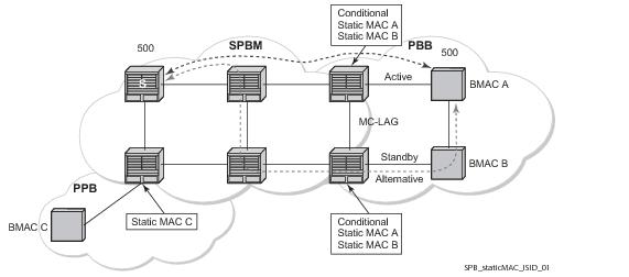
The root-and-leaf command is required; otherwise, this node will behave as a leaf only node by default. When the node is leaf only for the I-PMSI of type P2MP RSVP LSP, no PMSI Tunnel Attribute is included in BGP-AD route update messages and thus no RSVP P2MP LSP is signaled but the node can join RSVP P2MP LSP rooted at other PE nodes participating in this VPLS/B-VPLS service. Note that the user must still configure a LSP template even if the node is a leaf only. For the I-PMSI of type mLDP, the leaf-only node will join I-PMSI rooted at other nodes it discovered but will not include a PMSI Tunnel Attribute in BGP-AD route update messages. This way, a leaf only node will forward packets to other nodes in the VPLS/B-VPLS using the point-to-point spoke-sdps.
Note that BGP-AD must have been enabled in this VPLS/B-VPLS instance or the execution of the ‘no shutdown” command under the context of the inclusive node is failed and the I-PMSI will not come up. Also note that this feature is not supported with BGP-VPLS. As such, if both BGP-VPLS and BGP-AD are enabled, the execution of the “no shutdown” command under the context of the inclusive node is also failed. Also, if the I-PMSI is enabled the execution of the ‘no shutdown” command under BGP-VPLS is failed.
Any change to the parameters of the I-PMSI, such as disabling the P2MP LSP type or changing the LSP template requires that the inclusive node be first shutdown. The LSP template is configured in MPLS.
If the P2MP LSP instance goes down, VPLS/B-VPLS immediately reverts the forwarding of BUM packets to the P2P PWs. The user can, however, restore at any time the forwarding of BUM packets over the P2P PWs by performing a ‘shutdown’ under the context of the inclusive node.
This feature is supported with VPLS, H-VPLS, and B-VPLS. It is not supported with I-VPLS and Routed VPLS. It is also not supported with BGP-VPLS.
 
Routed VPLS and I-VPLS
 
IES or VPRN IP Interface Binding
A standard IP interface within an existing IES or VPRN service context may be bound to a service name. Subscriber and group IP interfaces are not allowed to bind to a VPLS or I-VPLS service context or I-VPLS. For the remainder of this section Routed VPLS and Routed I-VPLS will both be described as a VPLS service and differences will be pointed out where applicable. A VPLS service only supports binding for a single IP interface.
While an IP interface may only be bound to a single VPLS service, the routing context containing the IP interface (IES or VPRN) may have other IP interfaces bound to other VPLS service contexts of the same type (all VPLS or all I-VPLS). In other words, Routed VPLS allows the binding of IP interfaces in IES or VPRN services to be bound to VPLS services and Routed I-VPLS allows of IP interfaces in IES or VPRN services to be bound to I-VPLS services.
 
Assigning a Service Name to a VPLS Service
When a service name is applied to any service context, the name and service ID association is registered with the system. A service name cannot be assigned to more than one service ID.
Special consideration is given to a service name that is assigned to a VPLS service that has the configure>service>vpls>allow-ip-int-binding command is enabled. If a name is applied to the VPLS service while the flag is set, the system will scan the existing IES and VPRN services for an IP interface that is bound to the specified service name. If an IP interface is found, the IP interface will be attached to the VPLS service associated with the name. Only one interface can be bound to the specified name.
If the allow-ip-int-binding command is not enabled on the VPLS service, the system will not attempt to resolve the VPLS service name to an IP interface. As soon as the allow-ip-int-binding flag is configured on the VPLS, the corresponding IP interface will be bound and become operational up. There is no need to toggle the shutdown/no shutdown command.
If an IP interface is not currently bound to the service name used by the VPLS service, no action is taken at the time of the service name assignment.
 
Service Binding Requirements
In the event that the defined service ID is created on the system, the system will check to ensure that the service type is VPLS. If the service type is not VPLS or I-VPLS, service creation will not be allowed and the service ID will remain undefined within the system.
If the created service type is VPLS, the IP interface will be eligible to enter the operationally up state.
 
Bound Service Name Assignment
In the event that a bound service name is assigned to a service within the system, the system will first check to ensure the service type is VPLS or I-VPLS. Secondly the system will ensure that the service is not already bound to another IP interface via the service ID. If the service type is not VPLS or I-VPLS or the service is already bound to another IP interface via the service ID, the service name assignment will fail.
In the event that a single VPLS Service ID and service name is assigned to two separate IP interfaces, the VPLS service will not be allowed to enter and be operational/up state.
 
Binding a Service Name to an IP Interface
An IP interface within an IES or VPRN service context may be bound to a service name at anytime. Only one interface can be bound to a service.
When an IP interface is bound to a service name and the IP interface is administratively up, the system will scan for a VPLS service context using the name and take the following actions:
If the name is currently in use by a VPLS service without the allow-ip-int-binding flag set, the IP interface will be placed in the operationally down: VPLS service allow-ip-int-binding flag not set state. There is no need to toggle the shutdown/no shutdown command.
If the name is currently in use by a valid VPLS service and the allow-ip-int-binding flag is set, the IP interface will be eligible to be placed in the operationally up state depending on other operational criteria being met.
Bound Service Deletion or Service Name Removal
In the event that a VPLS service is deleted while bound to an IP interface, the IP interface will enter the ‘Down: Non-existent svc-ID’ operational state. If the IP interface was bound to the VPLS service name, the IP interface will enter the ‘Down: Non-existent svc-name’ operational state. No console warning is generated.
If the created service type is VPLS, the IP interface will be eligible to enter the operationally up state.
 
IP Interface Attached VPLS Service Constraints
Once a VPLS service has been bound to an IP interface through its service name, the service name assigned to the service cannot be removed or changed unless the IP interface is first unbound from the VPLS service name.
A VPLS service that is currently attached to an IP interface cannot be deleted from the system unless the IP interface is unbound from the VPLS service name.
The allow-ip-int-binding flag within an IP interface attached VPLS service cannot be reset. The IP interface must first be unbound from the VPLS service name to reset the flag.
 
IP Interface and VPLS Operational State Coordination
When the IP interface is successfully attached to a VPLS service, the operational state of the IP interface will be dependent upon the operational state of the VPLS service.
The VPLS service itself remains down until at least one virtual port (SAP, spoke-SDP or Mesh-SDP) is operational.
 
IP Interface MTU and Fragmentation
The VPLS service is affected by two MTU values; port MTUs and the VPLS service MTU. The MTU on each physical port defines the largest Layer 2packet (including all DLC headers) that may be transmitted out a port. The VPLS itself has a service level MTU that defines the largest packet supported by the service. This MTU does not include the local encapsulation overhead for each port (QinQ, Dot1Q, TopQ or SDP service delineation fields and headers) but does include the remainder of the packet. As virtual ports are created in the system, the virtual port cannot become operational unless the configured port MTU minus the virtual port service delineation overhead is greater than or equal to the configured VPLS service MTU. Thus, an operational virtual port is ensured to support the largest packet traversing the VPLS service. The service delineation overhead on each Layer 2 packet is removed before forwarding into a VPLS service. VPLS services do not support fragmentation and must discard any Layer 2 packet larger than the service MTU after the service delineation overhead is removed.
When an IP interface is associated with a VPLS service, the IP-MTU is based on either the administrative value configured for the IP interface or an operational value derived from VPLS service MTU. The operational IP-MTU cannot be greater than the VPLS service MTU minus 14 bytes.
 
Unicast IP Routing into a VPLS Service
The VPLS service MTU and the IP interface MTU parameters may be changed at anytime.
 
ARP and VPLS FIB Interactions
Two address-oriented table entries are used when routing into a VPLS service. On the routing side, an ARP entry is used to determine the destination MAC address used by an IP next-hop. In the case where the destination IP address in the routed packet is a host on the local subnet represented by the VPLS instance, the destination IP address itself is used as the next-hop IP address in the ARP cache lookup. If the destination IP address is in a remote subnet that is reached by another router attached to the VPLS service, the routing lookup will return the local IP address on the VPLS service of the remote router will be returned. If the next-hop is not currently in the ARP cache, the system will generate an ARP request to determine the destination MAC address associated with the next-hop IP address. IP routing to all destination hosts associated with the next-hop IP address stops until the ARP cache is populated with an entry for the next-hop. The ARP cache may be populated with a static ARP entry for the next-hop IP address. While dynamically populated ARP entries will age out according to the ARP aging timer, static ARP entries never age out.
The second address table entry that affects VPLS routed packets is the MAC destination lookup in the VPLS service context. The MAC associated with the ARP table entry for the IP next-hop may or may not currently be populated in the VPLS Layer 2FIB table. While the destination MAC is unknown (not populated in the VPLS FIB), the system will flood all packets destined to that MAC (routed or bridged) to all virtual ports within the VPLS service context. Once the MAC is known (populated in the VPLS FIB), all packets destined to the MAC (routed or bridged) will be targeted to the specific virtual port where the MAC has been learned. As with ARP entries, static MAC entries may be created in the VPLS FIB. Dynamically learned MAC addresses are allowed to age out or be flushed from the VPLS FIB while static MAC entries always remain associated with a specific virtual port. Dynamic MACs may also be relearned on another VPLS virtual port than the current virtual port in the FIB. In this case, the system will automatically move the MAC FIB entry to the new VPLS virtual port.
 
Routed VPLS Specific ARP Cache Behavior
In typical routing behavior, the system uses the IP route table to select the egress interface and then at the egress forwarding engine, an ARP entry is used forward the packet to the appropriate Ethernet MAC. With routed VPLS, the egress IP interface may be represented by multiple egress forwarding engine (wherever the VPLS service virtual ports exists).
In order to optimize routing performance, the ingress forwarding engine processing has been augmented to perform an ingress ARP lookup in order to resolve which VPLS MAC address the IP frame must be routed towards. This MAC address may be currently known or unknown within the VPLS FIB. If the MAC is unknown, the packet is flooded by the ingress forwarding engine to all egress forwarding engines where the VPLS service exists. When the MAC is known on a virtual port, the ingress forwarding engine forwards the packet to the proper egress forwarding engine. Table 2 describes how the ARP cache and MAC FIB entry states interact at ingress and Table 3 describes the corresponding egress behavior.


The allow-ip-int-binding VPLS Flag
The allow-ip-int-binding flag on a VPLS service context is used to inform the system that the VPLS service is enabled for routing support. The system uses the setting of the flag as a key to determine what type of ports and which type of forwarding planes the VPLS service may span.
The system also uses the flag state to define which VPLS features are configurable on the VPLS service to prevent enabling a feature that is not supported when routing support is enabled.
 
Routed VPLS SAPs Only Supported on Standard Ethernet Ports
The allow-ip-int-binding flag is set (routing support enabled) on a VPLS/I-VPLS service. SAPs within the service can be created on standard Ethernet, HSMDA., and CCAG ports. ATM and POS are not supported.
 
Routed VPLS SAPs Only Supported on FP2 (or later) Based Systems or IOM/IMM
The Ethernet ports must be populated on a FP2 or FP3 system IOMs in order for the routing enabled VPLS SAPs to be created.
 
Network Ports Restricted to FP2-Based Systems or IOMs
When at least one VPLS context is configured with the allow-ip-int-binding flag set, all ports within the system defined as mode network must be on an FP2 or greater forwarding plane. If one or more network ports are on an FP1 based forwarding plane, the allow-ip-int-binding flag cannot be set in a VPLS service context. Once the allow-ip-int-binding flag is set on a VPLS service context, a port on an FP1 based forwarding plane cannot be placed in mode network.
 
LAG Port Membership Constraints
If a LAG has a non-supported port type as a member, a SAP for the routing-enabled VPLS service cannot be created on the LAG. Once one or more routing enabled VPLS SAPs are associated with a LAG, a non-supported Ethernet port type cannot be added to the LAG membership.
 
Routed VPLS Feature Restrictions
When the allow-ip-int-binding flag is set on a VPLS service, the following features cannot be enabled (The flag also cannot be enabled while any of these features are applied to the VPLS service.):
Note: IES/VPRN Saps can be on non IOM3+ cards but traffic on them will not be forwarding on Routed VPLS/Routed I-VPLS
 
Routed I-VPLS Feature Restrictions
 
IES IP Interface VPLS Binding and Chassis Mode Interaction
It is possible to bind both IES and VPRN IP interfaces to a VPLS in chassis mode A. Chassis -mode D is not required.
 
VPRN IP Interface VPLS Binding and Forwarding Plane Constraints
When an IP interface within a VPRN service context is bound to a VPLS or an I-VPLS service name, all of the SAPs within the VPRN service context must be created on ports that are attached to FP2 forwarding planes or better. If a VPRN SAP is on a non-supported forwarding plane, the service name cannot be bound to the VPRN’s IP interface. Once an IP interface on the VPRN service is bound to a service name, a SAP on the VPRN service cannot be created on a port (or LAG) on an FP1 forwarding plane.
This restriction prevents a packet from entering the VPRN service on a port that cannot reach a routed VPLS next-hop.
 
Route Leaking Between Routing Contexts
While the system prevents a routing context from existing on FP1 based forwarding planes while a VPLS service is bound to the routing context, it is possible to create conditions using route leaking (importing or exporting routes using routing policies) where an FP1 based IP interface is asked to route to a routed VPLS next-hop. The system reacts to this condition by populating the next-hop in the FP1 forwarding plane with a null egress IP interface index. This causes any packets that are associated with that next-hop on an FP1 forwarding plane to be discarded. If ICMP destination unreachable messaging is enabled, unreachable messages will be sent.
 
Ingress LAG and FP1 to Routed VPLS Discards
If the chassis is connected by LAG to an upstream router and the LAG is split between FP1 and FP2 forwarding plane ports while routes have been shared between routing contexts, flows that are sent to the FP2 ports by the upstream router are capable of reaching a next-hop in a routed VPLS while flows going to the FP1 ports cannot.
 
IPv4 Multicast Routing Support
IPv4 multicast routing is supported when the source of the multicast stream is on the IP side of the routed VPLS service, and the multicast traffic is either flooded in the VPLS service or sent to IGMP clients. The IP interface supports the configuration of PIM and IGMP. When IGMP is configured on the IP interface, it is mandatory to enable. IGMP snooping in the VPLS service and to configure the associated IP interface to be both the PIM designated router and the IGMP querier in order that the multicast traffic is sent into the VPLS service, as IGMP joins are only propagated to the IP interface if it is the IGMP querier.
Figure 29: IPv4 Multicast with a Router VPLS service
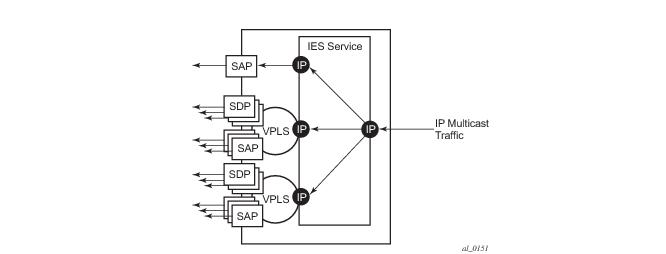
An example scenario is shown in Figure 29. The IP multicast traffic entering the system is replicated to IP interfaces, two of which are part of an IES routed VPLS service. The IP multicast traffic is sent only to those SAPs/SDPs from which a corresponding IGMP join has been received as igmp-snooping is enabled in the VPLS services.
It is possible to configure PIM on the IP interface and have neighboring downstream PIM routers connecting via the VPLS, however, any multicast traffic will be flooded in the VPLS service.
If a multicast source was connected by a SAP/SDP into the VPLS service, any multicast traffic would be replicated within the VPLS service but would be dropped at the routed VPLS IP interface.
 
BGP Auto Discovery (BGP-AD) for Routed VPLS Support
BGP Auto Discovery (BGP-AD) for Routed VPLS is supported. BGP-AD for LDP VPLS is an already supported framework for automatically discovering the endpoints of a Layer 2 VPN offering an operational model similar to that of an IP VPN.
 
Routed VPLS Caveats
 
VPLS SAP Ingress IP Filter Override
When an IP Interface is attached to a VPLS or an I-VPLS service context, the VPLS SAP provisioned IP filter for ingress routed packets may be optionally overridden in order to provide special ingress filtering for routed packets. This allows different filtering for routed packets and non-routed packets. The filter override is defined on the IP interface bound to the VPLS service name. A separate override filter may be specified for IPv4 and IPv6 packet types.
If a filter for a given packet type (IPv4 or IPv6) is not overridden, the SAP specified filter is applied to the packet (if defined).
 
IP Interface Defined Egress QoS Reclassification
The SAP egress QoS policy defined forwarding class and profile reclassification rules are not applied to egress routed packets. To allow for egress reclassification, a SAP egress QoS policy ID may be optionally defined on the IP interface which will be applied to routed packets that egress the SAPs on the VPLS or I-VPLS service associated with the IP interface. Both unicast directed and MAC unknown flooded traffic apply to this rule. Only the reclassification portion of the QoS policy is applied which includes IP precedence or DSCP classification rules and any defined IP match criteria and their associated actions.
The policers and queues defined within the QoS policy applied to the IP interface are not created on the egress SAPs of the VPLS service. Instead, the actual QoS policy applied to the egress SAPs defines the egress policers and queues that will be used by both routed and non-routed egress packets. The forwarding class mappings defined in the egress SAP’s QoS policy will also define which policer or queue will handle each forwarding class for both routed and non-routed packets.
 
VPLS Egress Remarking and Egress Routed Packets
The egress remaking defined in the SAP egress QoS policy is not performed for packets that are routed out an egress VPLS SAP. However, ingress derived egress remaking is performed for egress routed packets.
 
7450 Mixed Mode Chassis
The mixed mode on the 7450 that allows 7750 based IOM3s to be populated and operational in a 7450 chassis supports routed VPLS as long as all the forwarding plane and port type restrictions are observed.
 
IPv4 Multicast Routing
When using IPv4 Multicast routing, the following are not supported:
 
IPv4 Multicast Routing
When using IPv4 Multicast routing, the following are not supported:
 
Routed VPLS Supported Routing Related Protocols
The following protocols are supported on IP interfaces bound to a VPLS service:
Spanning Tree and Split Horizon
A routed VPLS context supports all spanning tree and split horizon capabilities that a non-routed VPLS service supports.
VPLS Service Considerations
This section describes various 7750 SR service features and any special capabilities or considerations as they relate to VPLS services.
 
SAP Encapsulations
VPLS services are designed to carry Ethernet frame payloads, so it can provide connectivity between any SAPs and SDPs that pass Ethernet frames. The following SAP encapsulations are supported on the 7750 SR VPLS service:
 
VLAN Processing
The SAP encapsulation definition on Ethernet ingress ports defines which VLAN tags are used to determine the service that the packet belongs:
1.
2.
3.
In situations 2 and 3 above, traffic encapsulated with tags for which there is no definition are discarded.
Ingress VLAN Swapping
This feature is supported on VPLS and VLL service where the end to end solution is built using two node solutions (requiring SDP connections between the nodes).
In VLAN swapping, only the VLAN-id value will be copied to the inner VLAN position. Ethertype of the inner tag will be preserved and all consecutive nodes will work with that value. Similarly, the dot1p bits value of outer-tag will not be preserved.
 
Figure 30: Ingress VLAN Swapping
The network diagram describes the network where at user access side (DSLAM facing SAPs) every subscriber is represented by several QinQ SAPs with inner-tag encoding service and outer-tag encoding subscriber (DSL line). The aggregation side (BRAS or PE facing SAPs) the is represented by DSL line number (inner VLAN tag) and DSLAM (outer VLAN tag). The effective operation on VLAN tag is to drop inner tag at access side and push another tag at the aggregation side.
 
Service Auto-Discovery using Multiple VLAN Registration Protocol (MVRP)
IEEE 802.1ak Multiple VLAN Registration Protocol (MVRP) is used to advertise throughout a native Ethernet switching domain one or multiple VLAN IDs to build automatically native Ethernet connectivity for multiple services. These VLAN IDs can be either Customer VLAN IDs (CVID) in an enterprise switching environment, Stacked VLAN IDs (SVID) in a Provider Bridging, QinQ Domain (see IEEE 802.1ad) or Backbone VLAN IDs (BVID) in a Provider Backbone Bridging (PBB) domain (see IEEE 802.1ah).
The initial focus of Alcatel-Lucent MVRP implementation is a Service Provider QinQ domain with or without a PBB core. The QinQ access into a PBB core example is used throughout this section to describe the MVRP implementation. With the exception of end-station components, a similar solution can be used to address a QinQ only or enterprise environments.
The components involved in the MVRP control plane are depicted in Figure 31.
 
 
Figure 31: Infrastructure for MVRP Exchanges
All the devices involved are QinQ switches with the exception of the PBB BEB which delimits the QinQ domain and ensures the transition to the PBB core. The red circles represent Management VPLS instances interconnected by SAPs to build a native Ethernet switching domain used for MVRP control plane exchanges.
The following high level steps are involved in auto-discovery of VLAN connectivity in a native Ethernet domain using MVRP:
 
Configure the MVRP Infrastructure using an M-VPLS Context
The following provisioning steps apply:
 
Instantiate Related VLAN FIBs and Trunks in MVRP Scope
This involves the configuration in the M-VPLS, under vpls-group of the following attributes: VLAN range(s), vpls-template and vpls-sap-template bindings. As soon as the VPLS group is enabled the configured attributes are used to auto-instantiate on a per VLAN basis a VPLS FIB and related SAP(s) in the switches and on the “trunk ports” specified in the M-VPLS context. The trunk ports are ports associated with an M-VPLS SAP not configured as an end-station.
The following procedure is used:
The above procedure may be used outside of the MVRP context to pre-provision a large number of VPLS contexts that share the same infrastructure and attributes.
The MVRP control of the auto-instantiated services can be enabled using the mvrp-contrl command under vpls-group:
From an MVRP perspective these SAPs can be either “full MVRP” or “end-stations” interfaces.
A full MVRP interface is a full participant in the local M-VPLS scope:
In an MVRP end-station the attribute(s) registered on that interface have local significance:
The following example describes the M-VPLS configuration required to auto-instantiate the VLAN FIBs and related trunks in non-PBB switches:
A similar M-VPLS configuration may be used to auto-instantiate the VLAN FIBs and related trunks in PBB switches. The vpls-group command is replaced by the end-station command under the downwards SAPs as in the following example:
 
MVRP Activation of Service Connectivity
As new Ethernet services are activated, UNI SAPs need to be configured and associated with the VLAN IDs (VPLS instances) auto-created using the procedures described in the previous sections. These UNI SAPs may be located in the same VLAN domain or over a PBB backbone. When UNI SAPs are located in different VLAN domains, an intermediate service translation point must be used at the PBB BEB which maps the local VLAN ID through an IVPLS SAP to a PBB ISID. This BEB SAP will be playing the role of an end-station from an MVRP perspective for the local VLAN domain. This section will discuss how MVRP is used to activate service connectivity between a BEB SAP and a UNI SAP located on one of the switches in the local domain. Similar procedure is used for the case of UNI SAPs configured on two switches located in the same access domain. No end-station configuration is required on the PBB BEB if all the UNI SAPs in a service are located in the same VLAN domain.
The service connectivity instantiation through MVRP is depicted in Figure 32.
Figure 32: Service Instantiation with MVRP - QinQ to PBB Example
In this example the UNI and service translation SAPs are configured in the data VPLS represented by the yellow circle. This instance and associated trunk SAPs were instantiated using the procedures described in the previous sections. The following configuration steps are involved:
As soon as the first UNI SAP becomes “active” in the data VPLS on the ES, the associated VLAN value is advertised by MVRP throughout the related M-VPLS context. As soon as the second UNI SAP becomes available on a different switch or in our example on the PBB BEB the MVRP proceeds to advertise the associated VLAN value throughout the same M-VPLS. The trunks that experience MVRP declaration and registration in both directions will become active instantiating service connectivity as represented by the big and small yellow circles depicted in the picture.
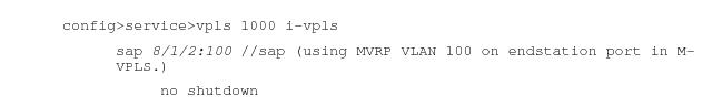
A hold-time parameter (config>service>vpls>mrp>mvrp>hold-time) is provided in the M-VPLS configuration to control when the end-station or last UNI SAP is considered active from an MVRP perspective. The hold-time controls the amount of MVRP advertisements generated on fast transitions of the end-station or UNI SAPs.
If the no hold-time setting is used:
If a non-zero “hold-time” setting is used:
Note that for QinQ endstation SAPs only “no hold-time” setting is allowed
Only the following PBB Epipe and I-VPLS SAP types are eligible to activate MVRP declarations:
An example of steps required to activate service connectivity for VLAN 100 using MVRP follows.
In the data VPLS instance (VLAN 100) controlled by MVRP, on the QinQ switch:
In I-VPLS on PBB BEB:
MVRP Control Plane
MVRP is based on the IEEE 802.1ak MRP specification where STP is the supported method to be used for loop avoidance in a native Ethernet environment. M-VPLS and associated MSTP (or P-MSTP) control plane provides the loop avoidance component in Alcatel-lucent implementation. Alcatel-Lucent MVRP may be used also in a non- MSTP, loop free topology.
 
STP-MVRP Interaction
The following table captures the expected interaction between STP (MSTP or P-MSTP) and MVRP:
 
Notes:
 
Interaction Between MVRP and Instantiated SAP Status
This section describes how MVRP reacts to changes in the instantiated SAP status.
 
There are a number of mechanisms that may generate operational or admin down status for the SAPs and VPLS instances controlled by MVRP:
1.
2.
3.
4.
Note that the shutdown of the whole instantiated VPLS or instantiated SAPs is disabled in both VPLS and VPLS SAP templates. The no shutdown option is automatically configured.
In the port down case MVRP will also be operationally down on the port so no VLAN declaration will take place.
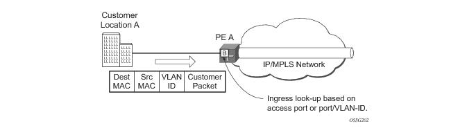
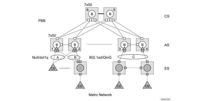
When MAC move is enabled in a data VPLS controlled by MVRP, in case a MAC move hit happens, one of the instantiated SAPs controlled by MVRP may be blocked. The SAP blocking by MAC Move is not reported though to the MVRP control plane. As a result MVRP keeps declaring and registering the related VLAN value on the control SAPs including the one which shares the same port with the instantiate SAP blocked by MAC move as long as MVRP conditions are met. For MVRP, an active control SAP is one that has MVRP enabled and MSTP is not blocking it for the VLAN value on the port. Also in the related data VPLS one of the two conditions must be met for the declaration of the VLAN value: there must be either a local user SAP or at least one MVRP registration received on one of the control SAPs for that VLAN.
In the last two cases VLAN attributes get declared or registered even when the instantiated SAP is operationally down, similarly with the MAC move case.
 
Using Temporary Flooding to Optimize Failover Times
MVRP advertisements use the active topology which may be controlled through loop avoidance mechanisms like MSTP. When the active topology changes as a result of network failures, the time it takes for MVRP to bring up the optimal service connectivity may be added on top of the regular MSTP convergence time. Full connectivity also depends on the time it takes for the system to complete flushing of bad MAC entries.
In order to minimize the effects of MAC Flushing and MVRP convergence, a temporary flooding behavior is implemented. When enabled the temporary flooding eliminates the time it takes to flush the MAC tables. In the initial implementation the temporary flooding is initiated only on reception of an STP TCN.
While temporary flooding is active all the frames received in the extended data VPLS context are flooded while the MAC flush and MVRP convergence takes place. The extended data VPLS context comprises all instantiated trunk SAPs regardless of MVRP activation status. A timer option is also available to configure a fixed amount of time, in seconds, during which all traffic is flooded (BUM or known unicast). Once the flood-time expires, traffic will be delivered according to the regular FIB content. The timer value should be configured to allow auxiliary processes like MAC Flush and MVRP to converge. The temporary flooding behavior applies to all VPLS types. Note that MAC learning continues during temporary flooding. Temporary flooding behavior is enabled using the temp-flooding command under config> service>vpls or config> service>template>vpls-template contexts and is supported in VPLS regardless of whether MVRP is enabled or not.
The following rules apply for temporary flooding in VPLS:
SPBM to Non SPBM Interworking
By using static definitions of B-MACs and ISIDs interworking of PBB Epipes and I-VPLS between SPBM networks and non SPBM PBB networks can be achieved.
 
Static MACs and Static ISIDs
To extend SPBM networks to other PBB networks, static MACs and ISIDs can be defined under SPBM SAPs/SDPs. The declaration of a static MAC in an SPBM context allows a non-SPBM PBB system to receive frames from an SPBM system. These static MACs are conditional on the SAP/SDP operational state. (Currently this is only supported for SPBM since SPBM can advertise these BMACs and ISIDs without any requirement for flushing.) The BMAC (and BMAC to ISID) must remain consistent when advertised in the IS-IS database.
The declaration of static-isids allows an efficient connection of ISID based services. The ISID is advertised as supported on the local nodal BMAC and the static BMACs which are the true destinations for the ISIDs are also advertised. When the I-VPLS learn the remote BMAC they will associated the ISID with the true destination BMAC. Therefore if redundancy is used the BMACs and ISIDs that are advertised must be the same on any redundant interfaces.
If the interface is an MC-LAG interface the static MAC and ISIDs on the SAPs/SDPs using that interface are only active when the associated MC-LAG interface is active. If the interface is a spoke SDP on an active/ standby pseudo wire (PW) the ISIDs and BMACs are only active when the PW is active.
 
Epipe Static Configuration
For Epipe only, the BMACs need to be advertised. There is no multicast for PBB epipes. Unicast traffic will follow the unicast path shortest path or single tree. By configuring remote BMACs Epipes can be setup to non SPBM systems. A special conditional static-mac is used for SPBM PBB B-VPLS SAPs/SDPs that are connected to a remote system. In the diagram ISID 500 is used for the PBB Epipe but only conditional MACs A and B are configured on the MC-LAG ports. The B-VPLS will advertise the static MAC either always or optionally based on a condition of the port forwarding.
 
Figure 33: Static MACs Example
 
I-VPLS Static Config
I-VPLS static config consists of two components: static-mac and static ISIDs that represent a remote BMAC-ISID combination.
The static-MACs are configured as with Epipe, the special conditional static-mac is used for SPBM PBB B-VPLS SAPs/SDPs that are connected to a remote system. The B-VPLS will advertise the static MAC either always or optionally based on a condition of the port forwarding.
The static-isids are created under the B-VPLS SAP/SDPs that are connected to a non-SPBM system. These ISIDs are typically advertised but may be controlled by ISID policy.
For I-VPLS ISIDs the ISIDs are advertised and multicast MAC are automatically created using PBB-OUI and the ISID. SPBM supports the pruned multicast single tree. Unicast traffic will follow the unicast path shortest path or single tree. Multicast/and unknown Unicast follow the pruned single tree for that ISID.
 
Figure 34: Static ISIDs Example
 
SPBM ISID Policies
Note that ISID policies are an optional aspect of SPBM which allow additional control of ISIDs for I-VPLS. PBB services using SPBM automatically populate multicast for I-VPLS and static-isids. Improper use of isid-policy can create black holes or additional flooding of multicast.
To enable more flexible multicast, ISID policies control the amount of MFIB space used by ISIDs by trading off the default Multicast tree and the per ISID multicast tree. Occasionally customers want services that use I-VPLS that have multiple sites but use primarily unicast. The ISID policy can be used on any node where an I-VPLS is defined or static ISIDs are defined.
The typical use is to suppress the installation of the ISID in the MFIB using use-def-mcast and the distribution of the ISID in SPBM by using no advertise-local.
The use-def-mcast policy instructs SPBM to use the default B-VPLS multicast forwarding for the ISID range. The ISID multicast frame remains unchanged by the policy (the standard format with the PBB OUI and the ISID as the multicast destination address) but no MFIB entry is allocated. This causes the forwarding to use the default BVID multicast tree which is not pruned. When this policy is in place it only governs the forwarding locally on the current B-VPLS.
The advertise local policy ISID policies are applied to both static ISIDs and I-VPLS ISIDs. The policies define whether the ISIDs are advertised in SPBM and whether the use the local MFIB. When ISIDs are advertised they will use the MFIB in the remote nodes. Locally the use of the MFIB is controlled by the use-def-mcast policy.
The types of interfaces are summarized in Table 5.
 
 
ISID Policy Control
 
Static ISID Advertisement
Static ISIDs are advertised between using the SPBM Service Identifier and Unicast Address sub-TLV in IS-IS when there is no ISID policy. This TLV advertises the local B-MAC and one or more ISIDs. The BMAC used is the source-bmac of the Control/User VPLS. Typically remote BMACs (the ultimate source-bmac) and the associated ISIDs are configured as static under the SPBM interface. This allows all remote BMACs and all remote ISIDs can be configured once per interface.
 
I-VPLS for Unicast Service
If the service is using unicast only an I-VPLS still uses MFIB space and SPBM advertises the ISID. By using the default multicast tree locally, a node saves MFIB space. By using the no advertise-local SPBM will not advertise the ISIDs covered by the policy. Note the actual PBB multicast frames are the same regardless of policy. Unicast traffic is the not changed for the ISID policies.
The Static BMAC configuration is allowed under Multi-Chassis LAG (MC-LAG) based SAPs and active/standby PW SDPs.
Unicast traffic will follow the unicast path shortest path or single tree. By using the ISID policy Multicast/and unknown Unicast traffic (BUM) follows the default B-VPLS tree in the SPBM domain. This should be used sparingly for any high volume of multicast services.
 
Figure 35: ISID Policy Example
 
Default Behaviors
When static ISIDs are defined the default is to advertise the static ISIDs when the interface parent (SAP or SDP) is up.
If the advertisement is not desired, an ISID policy can be created to prevent advertising the ISID.
Each Policy may be used alone or in combination.