For feedback, use the following:
ipd_online_feedback@alcatel-lucent.com
Table of Contents Previous Next Index PDF


Virtual Private Routed Network Service
In This Chapter
This chapter provides information about the Virtual Private Routed Network (VPN) service and implementation notes.
Topics in this chapter include:
VPRN Service Overview
RFC 2547b is an extension to the original RFC 2547, BGP/MPLS VPNs, which details a method of distributing routing information using BGP and MPLS forwarding data to provide a Layer 3 Virtual Private Network (VPN) service to end customers.
Each Virtual Private Routed Network (VPRN) consists of a set of customer sites connected to one or more PE routers. Each associated PE router maintains a separate IP forwarding table for each VPRN. Additionally, the PE routers exchange the routing information configured or learned from all customer sites via MP-BGP peering. Each route exchanged via the MP-BGP protocol includes a Route Distinguisher (RD), which identifies the VPRN association and handles the possibility of IP address overlap.
The service provider uses BGP to exchange the routes of a particular VPN among the PE routers that are attached to that VPN. This is done in a way which ensures that routes from different VPNs remain distinct and separate, even if two VPNs have an overlapping address space. The PE routers peer with locally connected CE routers and exchange routes with other PE routers in order to provide end-to-end connectivity between CEs belonging to a given VPN. Since the CE routers do not peer with each other there is no overlay visible to the CEs.
When BGP distributes a VPN route, it also distributes an MPLS label for that route. On a SR-Series, the label distributed with a VPN route depends on the configured label-mode of the VPRN that is originating the route
Before a customer data packet travels across the service provider's backbone, it is encapsulated with the MPLS label that corresponds, in the customer's VPN, to the route which best matches the packet's destination address. The MPLS packet is further encapsulated with one or additional MPLS labels or GRE tunnel header so that it gets tunneled across the backbone to the proper PE router. Each route exchanged by the MP-BGP protocol includes a route distinguisher (RD), which identifies the VPRN association. Thus the backbone core routers do not need to know the VPN routes. Figure 89 displays a VPRN network diagram example.
 
Figure 89: Virtual Private Routed Network
 
Routing Prerequisites
RFC4364 requires the following features:
Tunneling protocol options are as follows:
 
Core MP-BGP Support
BGP is used with BGP extensions mentioned in Routing Prerequisites to distribute VPRN routing information across the service provider’s network.
BGP was initially designed to distribute IPv4 routing information. Therefore, multi-protocol extensions and the use of a VPN-IP address were created to extend BGP’s ability to carry overlapping routing information. A VPN-IPv4 address is a 12-byte value consisting of the 8-byte route distinguisher (RD) and the 4-byte IPv4 IP address prefix. A VPN-IPv6 address is a 24-byte value consisting of the 8-byte RD and 16-byte IPv6 address prefix. Service providers typically assign one or a small number of RDs per VPN service network-wide.
 
Route Distinguishers
The route distinguisher (RD) is an 8-byte value consisting of two major fields, the Type field and Value field. The Type field determines how the Value field should be interpreted. The 7750 SR OS implementation supports the three (3) Type values as defined in the standard.
Figure 90: Route Distinguisher
The three Type values are:
The administrator field must contain an AS number (using private AS numbers is discouraged). The Assigned field contains a number assigned by the service provider.
The administrator field must contain an IP address (using private IP address space is discouraged). The Assigned field contains a number assigned by the service provider.
The administrator field must contain a 4-byte AS number (using private AS numbers is discouraged). The Assigned field contains a number assigned by the service provider.
 
eiBGP Load Balancing
eiBGP load balancing allows a route to have multiple nexthops of different types, using both IPv4 nexthops and MPLS LSPs simultaneously.
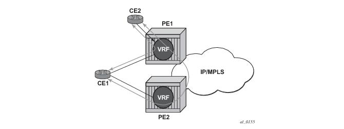
Figure 91 displays a basic topology that could use eiBGP load balancing. In this topology CE1 is dual homed and thus reachable by two separate PE routers. CE 2 (a site in the same VPRN) is also attached to PE1. With eiBGP load balancing, PE1 will utilize its own local IPv4 nexthop as well as the route advertised by MP-BGP, by PE2.
Figure 91: Basic eiBGP Topology
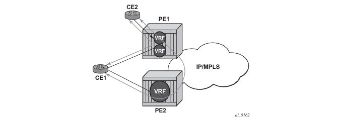
Another example displayed in Figure 92 shows an extra net VPRN (VRF). The traffic ingressing the PE that should be load balanced is part of a second VPRN and the route over which the load balancing is to occur is part of a separate VPRN instance and are leaked into the second VPRN by route policies.
Here, both routes can have a source protocol of VPN-IPv4 but one will still have an IPv4 nexthop and the other can have a VPN-IPv4 nexthop pointing out a network interface. Traffic will still be load balanced (if eiBGP is enabled) as if only a single VRF was involved.
Figure 92: Extranet Load Balancing
Traffic will be load balanced across both the IPv4 and VPN-IPv4 next hops. This helps to use all available bandwidth to reach a dual-homed VPRN.
 
Route Reflector
The use of Route Reflectors is supported in the service provider core. Multiple sets of route reflectors can be used for different types of BGP routes, including IPv4 and VPN-IPv4 as well as multicast and IPv6.
 
CE to PE Route Exchange
Routing information between the Customer Edge (CE) and Provider Edge (PE) can be exchanged by the following methods:
Each protocol provides controls to limit the number of routes learned from each CE router.
 
Route Redistribution
Routing information learned from the CE-to-PE routing protocols and configured static routes should be injected in the associated local VPN routing/forwarding (VRF). In the case of dynamic routing protocols, there may be protocol specific route policies that modify or reject certain routes before they are injected into the local VRF.
Route redistribution from the local VRF to CE-to-PE routing protocols is to be controlled via the route policies in each routing protocol instance, in the same manner that is used by the base router instance.
The advertisement or redistribution of routing information from the local VRF to or from the MP-BGP instance is specified per VRF and is controlled by VRF route target associations or by VRF route policies.
VPN-IP routes imported into a VPRN, have the protocol type bgp-vpn to denote that it is an VPRN route. This can be used within the route policy match criteria.
 
CPE Connectivity Check
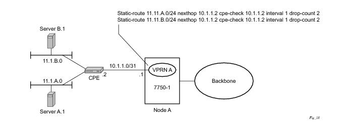
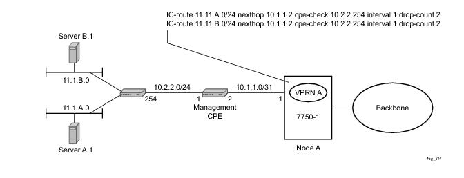
Static routes are used within many IES and VPRN services. Unlike dynamic routing protocols, there is no way to change the state of routes based on availability information for the associated CPE. CPE connectivity check adds flexibility so that unavailable destinations will be removed from the VPRN routing tables dynamically and minimize wasted bandwidth.
Figure 93: Directly Connected IP Target
Figure 94: Multiple Hops to IP Target
The availability of the far-end static route is monitored through periodic polling. The polling period is configured. If the poll fails a specified number of sequential polls, the static route is marked as inactive.
Either ICMP ping or unicast ARP mechanism can be used to test the connectivity. ICMP ping is preferred.
If the connectivity check fails and the static route is de-activated, the SR-Series router will continue to send polls and re-activate any routes that are restored.
 
Constrained Route Distribution (RT Constraint)
 
Constrained VPN Route Distribution Based on Route Targets
Constrained Route Distribution (or RT Constraint) is a mechanism that allows a router to advertise Route Target membership information to its BGP peers to indicate interest in receiving only VPN routes tagged with specific Route Target extended communities. Upon receiving this information, peers restrict the advertised VPN routes to only those requested, minimizing control plane load in terms of protocol traffic and possibly also RIB memory.
The Route Target membership information is carried using MP-BGP, using an AFI value of 1 and SAFI value of 132. In order for two routers to exchange RT membership NLRI they must advertise the corresponding AFI/SAFI to each other during capability negotiation. The use of MP-BGP means RT membership NLRI are propagated, loop-free, within an AS and between ASes using well-known BGP route selection and advertisement rules.
ORF can also be used for RT-based route filtering, but ORF messages have a limited scope of distribution (to direct peers) and therefore do not automatically create pruned inter-cluster and inter-AS route distribution trees.
 
Configuring the Route Target Address Family
RT Constraint is supported only by the base router BGP instance. When the family command at the BGP router group or neighbor CLI context includes the route-target keyword, the RT Constraint capability is negotiated with the associated set of EBGP and IBGP peers.
ORF is mutually exclusive with RT Constraint on a particular BGP session. The CLI will not attempt to block this configuration, but if both capabilities are enabled on a session, the ORF capability will not be included in the OPEN message sent to the peer.
 
Originating RT Constraint Routes
When the base router has one or more RTC peers (BGP peers with which the RT Constraint capability has been successfully negotiated), one RTC route is created for each RT extended community imported (for unicast connectivity) by locally-configured VPRN services.
By default, these RTC routes are automatically advertised to all RTC peers, without the need for an export policy to explicitly “accept” them. Each RTC route has a prefix, a prefix length and path attributes. The prefix value is the concatenation of the origin AS (a 4 byte value representing the 2- or 4-octet AS of the originating router, as configured using the config>router>autonomous-system command) and 0 or 16-64 bits of a route target extended community encoded in one of the following formats: 2-octet AS specific extended community, IPv4 address specific extended community, or 4-octet AS specific extended community.
A 7750 SR may be configured to send the default RTC route to any RTC peer. This is done using the new default-route-target group/neighbor CLI command. The default RTC route is a special type of RTC route that has zero prefix length. Sending the default RTC route to a peer conveys a request to receive all VPN routes (regardless of route target extended community) from that peer. The default RTC route is typically advertised by a route reflector to its clients. The advertisement of the default RTC route to a peer does not suppress other more specific RTC routes from being sent to that peer.
 
Receiving and Re-Advertising RT Constraint Routes
All received RTC routes that are deemed valid are stored in the RIB-IN. An RTC route is considered invalid and treated as withdrawn, if any of the following applies:
If multiple RTC routes are received for the same prefix value then standard BGP best path selection procedures are used to determine the best of these routes.
The best RTC route per prefix is re-advertised to RTC peers based on the following rules:
Note: These advertisement rules do not handle hierarchical RR topologies properly. This is a limitation of the current RT constraint standard.
 
Using RT Constraint Routes
In general (ignoring IBGP-to-IBGP rules, Add-Path, Best-external, etc.), the best VPN route for every prefix/NLRI in the RIB is sent to every peer supporting the VPN address family, but export policies may be used to prevent some prefix/NLRI from being advertised to specific peers. These export policies may be configured statically or created dynamically based on the support of ORF with specific peers. RT Constraint introduces another mechanism for dynamic modification of export policies. In R10, ORF and RT Constraint are mutually exclusive on a session.
When RT Constraint is configured on a session that also supports VPN address families using route targets (that is, L2-VPN, VPN-IPv4, VPN-IPv6, MVPN, MDT-SAFI), the advertisement of the VPN routes is affected as follows:
Note: This applies whether or not P1 advertised the best route for the default RTC prefix.
No MVPN, MDT-SAFI, or L2-VPN routes are sent as a result of receiving the default RTC route.
In this context, a default RTC route is any of the following:
Note: This applies whether or not I1 advertised the best route for A.
No MVPN, MDT-SAFI or L2-VPN routes are sent as a result of receiving the RTC route.
Note: This applies only if I1 advertised the best route for A.
No MVPN, MDT-SAFI, or L2-VPN routes are sent as a result of receiving the RTC route.
Note: This applies only if E1 advertised the best route for A.
No MVPN, MDT-SAFI or L2-VPN routes are sent as a result of receiving the RTC route.
 
BGP Fast Reroute in a VPRN
BGP fast reroute is a feature that brings together indirection techniques in the forwarding plane and pre-computation of BGP backup paths in the control plane to support fast reroute of BGP traffic around unreachable/failed next-hops. In a VPRN context BGP fast reroute is supported using unlabeled IPv4, unlabeled IPv6, VPN-IPv4, and VPN-IPv6 VPN routes. The supported VPRN scenarios are outlined in Table 23.
Note that BGP fast reroute information specific to the base router BGP context is described in the BGP Fast Reroute section of the 7x50 SR OS Routing Protocols Guide.


BGP Fast Reroute in a VPRN Configuration
Configuring the backup-path command under config>service>vprn>bgp causes only routes learned from CE BGP peers to be considered when selecting the primary and backup paths. Configuring the enable-bgp-vpn-backup command under config>service>vprn causes imported BGP-VPN routes to be compared to CE BGP routes when selecting the primary and backup paths. This command is required to support fast failover of ingress traffic from one remote PE to another remote PE and to support fast failover of egress traffic from a locally connected CE to a remote PE.
VPRN Features
This section describes various VPRN features and any special capabilities or considerations as they relate to VPRN services.
 
IP Interfaces
VPRN customer IP interfaces can be configured with most of the same options found on the core IP interfaces. The advanced configuration options supported are:
Configuration options found on core IP interfaces not supported on VPRN IP interfaces are:
 
 
QoS Policy Propagation Using BGP (QPPB)
This section discusses QPPB as it applies to VPRN, IES, and router interfaces. Refer to the QoS Policy Propagation Using BGP (QPPB) section on and the IP Router Configuration section in the 7x50 OS Router Configuration Guide.
QoS policy propagation using BGP (QPPB) is a feature that allows a route to be installed in the routing table with a forwarding-class and priority so that packets matching the route can receive the associated QoS. The forwarding-class and priority associated with a BGP route are set using BGP import route policies. In the industry this feature is called QPPB, and even though the feature name refers to BGP specifically. On SR routers, QPPB is supported for BGP (IPv4, IPv6, VPN-IPv4, VPN-IPv6), RIP and static routes.
While SAP ingress and network QoS policies can achieve the same end result as QPPB, assigning a packet arriving on a particular IP interface to a specific forwarding-class and priority/profile based on the source IP address or destination IP address of the packet �the effort involved in creating the QoS policies, keeping them up-to-date, and applying them across many nodes is much greater than with QPPB. In a typical application of QPPB, a BGP route is advertised with a BGP community attribute that conveys a particular QoS. Routers that receive the advertisement accept the route into their routing table and set the forwarding-class and priority of the route from the community attribute.
 
QPPB Applications
There are two typical applications of QPPB:
1.
2. Traffic differentiation within a single domain, based on route characteristics.
 
Inter-AS Coordination of QoS Policies
The operator of an administrative domain A can use QPPB to signal to a peer administrative domain B that traffic sent to certain prefixes advertised by domain A should receive a particular QoS treatment in domain B. More specifically, an ASBR of domain A can advertise a prefix XYZ to domain B and include a BGP community attribute with the route. The community value implies a particular QoS treatment, as agreed by the two domains (in their peering agreement or service level agreement, for example). When the ASBR and other routers in domain B accept and install the route for XYZ into their routing table, they apply a QoS policy on selected interfaces that classifies traffic towards network XYZ into the QoS class implied by the BGP community value.
QPPB may also be used to request that traffic sourced from certain networks receive appropriate QoS handling in downstream nodes that may span different administrative domains. This can be achieved by advertising the source prefix with a BGP community, as discussed above. However, in this case other approaches are equally valid, such as marking the DSCP or other CoS fields based on source IP address so that downstream domains can take action based on a common understanding of the QoS treatment implied by different DSCP values.
In the above examples, coordination of QoS policies using QPPB could be between a business customer and its IP VPN service provider, or between one service provider and another.
 
Traffic Differentiation Based on Route Characteristics
There may be times when a network operator wants to provide differentiated service to certain traffic flows within its network, and these traffic flows can be identified with known routes. For example, the operator of an ISP network may want to give priority to traffic originating in a particular ASN (the ASN of a content provider offering over-the-top services to the ISP’s customers), following a certain AS_PATH, or destined for a particular next-hop (remaining on-net vs. off-net).
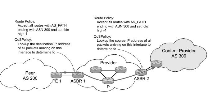
Figure 95 shows an example of an ISP that has an agreement with the content provider managing AS300 to provide traffic sourced and terminating within AS300 with differentiated service appropriate to the content being transported. In this example we presume that ASBR1 and ASBR2 mark the DSCP of packets terminating and sourced, respectively, in AS300 so that other nodes within the ISP’s network do not need to rely on QPPB to determine the correct forwarding-class to use for the traffic. Note however, that the DSCP or other COS markings could be left unchanged in the ISP’s network and QPPB used on every node.
Figure 95: Use of QPPB to Differentiate Traffic in an ISP Network
QPPB
There are two main aspects of the QPPB feature:
 
Associating an FC and Priority with a Route
This feature uses a command in the route-policy hierarchy to set the forwarding class and optionally the priority associated with routes accepted by a route-policy entry. The command has the following structure:
 fc fc-name [priority {low | high}]
The use of this command is illustrated by the following example:
config>router>policy-options
begin
community gold members 300:100
policy-statement qppb_policy
entry 10
from
protocol bgp
community gold
exit
action accept
fc h1 priority high
exit
exit
exit
commit
 
The fc command is supported with all existing from and to match conditions in a route policy entry and with any action other than reject, it is supported with next-entry, next-policy and accept actions. If a next-entry or next-policy action results in multiple matching entries then the last entry with a QPPB action determines the forwarding class and priority.
A route policy that includes the fc command in one or more entries can be used in any import or export policy but the fc command has no effect except in the following types of policies:
As evident from above, QPPB route policies support routes learned from RIP and BGP neighbors of a VPRN as well as for routes learned from RIP and BGP neighbors of the base/global routing instance.
QPPB is supported for BGP routes belonging to any of the address families listed below:
Note that a VPN-IP route may match both a VRF import policy entry and a BGP import policy entry (if vpn-apply-import is configured in the base router BGP instance). In this case the VRF import policy is applied first and then the BGP import policy, so the QPPB QoS is based on the BGP import policy entry.
This feature also introduces the ability to associate a forwarding-class and optionally priority with IPv4 and IPv6 static routes. This is achieved using the following modified versions of the static-route commands:
static-route {ip-prefix/prefix-length|ip-prefix netmask} [fc fc-name [priority {low | high}]] next-hop ip-int-name|ip-address
static-route {ip-prefix/prefix-length|ip-prefix netmask} [fc fc-name [priority {low | high}]] indirect ip-address
Priority is optional when specifying the forwarding class of a static route, but once configured it can only be deleted and returned to unspecified by deleting the entire static route.
Displaying QoS Information Associated with Routes
The following commands are enhanced to show the forwarding-class and priority associated with the displayed routes:
This feature uses a qos keyword to the show>router>route-table command. When this option is specified the output includes an additional line per route entry that displays the forwarding class and priority of the route. If a route has no fc and priority information then the third line is blank. The following CLI shows an example:
show router route-table [family] [ip-prefix[/prefix-length]] [longer | exact] [protocol protocol-name] qos
An example output of this command is shown below:
A:Dut-A# show router route-table 10.1.5.0/24 qos
===============================================================================
Route Table (Router: Base)
===============================================================================
Dest Prefix Type Proto Age Pref
Next Hop[Interface Name] Metric
QoS
-------------------------------------------------------------------------------
10.1.5.0/24 Remote BGP 15h32m52s 0
PE1_to_PE2 0
h1, high
-------------------------------------------------------------------------------
No. of Routes: 1
===============================================================================
A:Dut-A#


Enabling QPPB on an IP interface
To enable QoS classification of ingress IP packets on an interface based on the QoS information associated with the routes that best match the packets the qos-route-lookup command is necessary in the configuration of the IP interface. The qos-route-lookup command has parameters to indicate whether the QoS result is based on lookup of the source or destination IP address in every packet. There are separate qos-route-lookup commands for the IPv4 and IPv6 packets on an interface, which allows QPPB to enabled for IPv4 only, IPv6 only, or both IPv4 and IPv6. Note however, current QPPB based on a source IP address is not supported for IPv6 packets nor is it supported for ingress subscriber management traffic on a group interface.
The qos-route-lookup command is supported on the following types of IP interfaces:
When the qos-route-lookup command with the destination parameter is applied to an IP interface and the destination address of an incoming IP packet matches a route with QoS information the packet is classified to the fc and priority associated with that route, overriding the fc and priority/profile determined from the sap-ingress or network qos policy associated with the IP interface (see section 5.7 for further details). If the destination address of the incoming packet matches a route with no QoS information the fc and priority of the packet remain as determined by the sap-ingress or network qos policy.
Similarly, when the qos-route-lookup command with the source parameter is applied to an IP interface and the source address of an incoming IP packet matches a route with QoS information the packet is classified to the fc and priority associated with that route, overriding the fc and priority/profile determined from the sap-ingress or network qos policy associated with the IP interface. If the source address of the incoming packet matches a route with no QoS information the fc and priority of the packet remain as determined by the sap-ingress or network qos policy.
Currently, QPPB is not supported for ingress MPLS traffic on network interfaces or on CsC PE’-CE’ interfaces (config>service>vprn>nw-if).


QPPB When Next-Hops are Resolved by QPPB Routes
In some circumstances (IP VPN inter-AS model C, Carrier Supporting Carrier, indirect static routes, etc.) an IPv4 or IPv6 packet may arrive on a QPPB-enabled interface and match a route A1 whose next-hop N1 is resolved by a route A2 with next-hop N2 and perhaps N2 is resolved by a route A3 with next-hop N3, etc. In release 9.0 the QPPB result is based only on the forwarding-class and priority of route A1. If A1 does not have a forwarding-class and priority association then the QoS classification is not based on QPPB, even if routes A2, A3, etc. have forwarding-class and priority associations.
 
QPPB and Multiple Paths to a Destination
When ECMP is enabled some routes may have multiple equal-cost next-hops in the forwarding table. When an IP packet matches such a route the next-hop selection is typically based on a hash algorithm that tries to load balance traffic across all the next-hops while keeping all packets of a given flow on the same path. The QPPB configuration model described in Associating an FC and Priority with a Route allows different QoS information to be associated with the different ECMP next-hops of a route. The forwarding-class and priority of a packet matching an ECMP route is based on the particular next-hop used to forward the packet.
When BGP FRR is enabled some BGP routes may have a backup next-hop in the forwarding table in addition to the one or more primary next-hops representing the equal-cost best paths allowed by the ECMP/multipath configuration. When an IP packet matches such a route a reachable primary next-hop is selected (based on the hash result) but if all the primary next-hops are unreachable then the backup next-hop is used. The QPPB configuration model described in Associating an FC and Priority with a Route allows the forwarding-class and priority associated with the backup path to be different from the QoS characteristics of the equal-cost best paths. The forwarding class and priority of a packet forwarded on the backup path is based on the fc and priority of the backup route.
 
QPPB and Policy-Based Routing
When an IPv4 or IPv6 packet with destination address X arrives on an interface with both QPPB and policy-based-routing enabled:
 
QPPB and GRT Lookup
Source-address based QPPB is not supported on any SAP or spoke SDP interface of a VPRN configured with the grt-lookup command.
 
QPPB Interaction with SAP Ingress QoS Policy
When QPPB is enabled on a SAP IP interface the forwarding class of a packet may change from fc1, the original fc determined by the SAP ingress QoS policy to fc2, the new fc determined by QPPB. In the ingress datapath SAP ingress QoS policies are applied in the first P chip and route lookup/QPPB occurs in the second P chip. This has the implications listed below:
The profile state of a SAP ingress packet that matches a QPPB route depends on the configuration of fc2 only. If the de-1-out-profile flag is enabled in fc2 and fc2 is not mapped to a priority mode queue then the packet will be marked out of profile if its DE bit = 1. If the profile state of fc2 is explicitly configured (in or out) and fc2 is not mapped to a priority mode queue then the packet is assigned this profile state. In both cases there is no consideration of whether or not fc1 was mapped to a priority mode queue.
The priority of a SAP ingress packet that matches a QPPB route depends on several factors. If the de-1-out-profile flag is enabled in fc2 and the DE bit is set in the packet then priority will be low regardless of the QPPB priority or fc2 mapping to profile mode queue, priority mode queue or policer. If fc2 is associated with a profile mode queue then the packet priority will be based on the explicitly configured profile state of fc2 (in profile = high, out profile = low, undefined = high), regardless of the QPPB priority or fc1 configuration. If fc2 is associated with a priority mode queue or policer then the packet priority will be based on QPPB (unless DE=1), but if no priority information is associated with the route then the packet priority will be based on the configuration of fc1 (if fc1 mapped to a priority mode queue then it is based on DSCP/IP prec/802.1p and if fc1 mapped to a profile mode queue then it is based on the profile state of fc1).
Table 24 summarizes these interactions.


Object Grouping and State Monitoring
This feature introduces a generic operational group object which associates different service endpoints (pseudowires and SAPs) located in the same or in different service instances. The operational group status is derived from the status of the individual components using certain rules specific to the application using the concept. A number of other service entities, the monitoring objects, can be configured to monitor the operational group status and to perform certain actions as a result of status transitions. For example, if the operational group goes down, the monitoring objects will be brought down.
 
VPRN IP Interface Applicability
This concept is used by an IPv4 VPRN interface to affect the operational state of the IP interface monitoring the operational group. Individual SAP and spoke SDPs are supported as monitoring objects.
The following rules apply:
There are two steps involved in enabling the functionality:
1.
2. Associate the IP interface to the oper-group using the monitor-group command
The status of the operational group (oper-group) is dictated by the status of one or more members according to the following rule:
The simple configuration below shows the oper-group g1, the VPLS SAP that is mapped to it and the IP interfaces in VPRN service 2001 monitoring the oper-group g1. This is example uses an R-VPLS context. The VPLS instance includes the allow-ip-int-binding and the service-name v1. The VPRN interface links to the VPLS using the vpls v1 option. All commands are under the configuration service hierarchy.
To further explain the configuration. Oper-group g1 has a single SAP (1/1/1:2001) mapped to it and the IP interfaces in the VPRN service 2001 will derive its state from the state of oper-group g1.
	oper-group g1 create
 
vpls 1 customer 1 create
allow-ip-int-binding
stp
shutdown
exit
service-name "v1"
sap 1/1/1:2001 create
oper-group g1
eth-cfm
mep domain 1 association 1 direction down
ccm-enable
no shutdown
exit
exit
sap 1/1/2:2001 create
exit
sap 1/1/3:2001 create
exit
no shutdown
 
 
vprn 2001 customer 1 create
interface "i2001" create
address 21.1.1.1/24
monitor-oper-group "g1"
vpls "v1"
exit
no shutdown
exit
 
Subscriber Interfaces
Subscriber interfaces are composed of a combination of two key technologies, subscriber interfaces and group interfaces. While the subscriber interface defines the subscriber subnets, the group interfaces are responsible for aggregating the SAPs.
 
SAPs
 
Encapsulations
The following SAP encapsulations are supported on the 7750 SR VPRN service:
 
ATM SAP Encapsulations for VPRN Services
The SR-Series series supports ATM PVC service encapsulation for VPRN SAPs. Both UNI and NNI cell formats are supported. The format is configurable on a SONET/SDH path basis. A path maps to an ATM VC. All VCs on a path must use the same cell format.
The following ATM encapsulation and transport modes are supported:
RFC 2684, Multiprotocol Encapsulation over ATM Adaptation Layer 5:
 
Pseudowire SAPs
PW SAPs are supported on VPRN interfaces.For details of PW SAPs, see the section Pseudowire SAPs of this user guide.
 
QoS Policies
When applied to a VPRN SAP, service ingress QoS policies only create the unicast queues defined in the policy if PIM is not configured on the associated IP interface; if PIM is configured, the multipoint queues are applied as well.
With VPRN services, service egress QoS policies function as with other services where the class-based queues are created as defined in the policy.
Note that both Layer 2 or Layer 3 criteria can be used in the QoS policies for traffic classification in an VPRN.
 
Filter Policies
Ingress and egress IPv4 and IPv6 filter policies can be applied to VPRN SAPs.
 
 
DSCP Marking
Specific DSCP, forwarding class, and Dot1P parameters can be specified to be used by every protocol packet generated by the VPRN. This enables prioritization or de-prioritization of every protocol (as required). The markings effect a change in behavior on ingress when queuing. For example, if OSPF is not enabled, then traffic can be de-prioritized to best effort (be) DSCP. This change de-prioritizes OSPF traffic to the CPU complex.
DSCP marking for internally generated control and management traffic by marking the DSCP value should be used for the given application. This can be configured per routing instance. For example, OSPF packets can carry a different DSCP marking for the base instance and then for a VPRN service. ISIS and ARP traffic is not an IP-generated traffic type and is not configurable.
When an application is configured to use a specified DSCP value then the MPLS EXP, Dot1P bits will be marked in accordance with the network or access egress policy as it applies to the logical interface the packet will be egressing.
The DSCP value can be set per application. This setting will be forwarded to the egress linecard. The egress linecard does not alter the coded DSCP value and marks the LSP-EXP and IEEE 802.1p (Dot1P) bits according to the appropriate network or access QoS policy.


Default DSCP Mapping Table
 
DSCP Name DSCP Value DSCP Value DSCP Value Label
Decimal Hexadecimal Binary
=============================================================
Default 0 0x00 0b000000 be
nc1 48 0x30 0b110000 h1
nc2 56 0x38 0b111000 nc
ef 46 0x2e 0b101110 ef
af11 10 0x0a 0b001010 assured
af12 12 0x0c 0b001100 assured
af13 14 0x0e 0b001110 assured
af21 18 0x12 0b010010 l1
af22 20 0x14 0b010100 l1
af23 22 0x16 0b010110 l1
af31 26 0x1a 0b011010 l1
af32 28 0x1c 0b011100 l1
af33 30 0x1d 0b011110 l1
af41 34 0x22 0b100010 h2
af42 36 0x24 0b100100 h2
af43 38 0x26 0b100110 h2
 
default* 0
 
*The default forwarding class mapping is used for all DSCP names/values for which there is no explicit forwarding class mapping.
 
 
CE to PE Routing Protocols
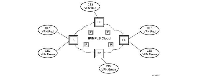
The 7750 SR VPRN supports the following PE to CE routing protocols:
 
PE to PE Tunneling Mechanisms
The 7750 SR supports multiple mechanisms to provide transport tunnels for the forwarding of traffic between PE routers within the 2547bis network.
The 7750 SR VPRN implementation supports the use of:
These transport tunnel mechanisms provide the flexibility of using dynamically created LSPs where the service tunnels are automatically bound (the “autobind” feature) and the ability to provide certain VPN services with their own transport tunnels by explicitly binding SDPs if desired. When the autobind is used, all services traverse the same LSPs and do not allow alternate tunneling mechanisms (like GRE) or the ability to craft sets of LSP's with bandwidth reservations for specific customers as is available with explicit SDPs for the service.
 
Per VRF Route Limiting
The 7750 SR allows setting the maximum number of routes that can be accepted in the VRF for a VPRN service. There are options to specify a percentage threshold at which to generate an event that the VRF table is near full and an option to disable additional route learning when full or only generate an event.
 
Spoke SDPs
Distributed services use service distribution points (SDPs) to direct traffic to another SR-Series router via service tunnels. SDPs are created on each participating SR-Series and then bound to a specific service. SDP can be created as either GRE or MPLS. Refer to Service Distribution Points (SDPs) for information about configuring SDPs.
This feature provides the ability to cross-connect traffic entering on a spoke SDP, used for Layer 2 services (VLLs or VPLS), on to an IES or VPRN service. From a logical point of view, the spoke SDP entering on a network port is cross-connected to the Layer 3 service as if it entered by a service SAP. The main exception to this is traffic entering the Layer 3 service by a spoke SDP is handled with network QoS policies not access QoS policies.
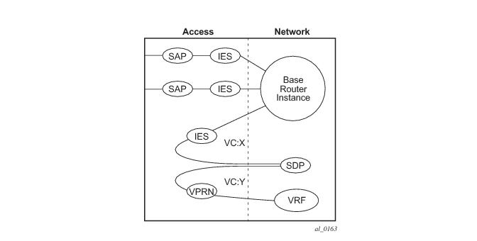
Figure 96 depicts traffic terminating on a specific IES or VPRN service that is identified by the sdp-id and VC label present in the service packet.
Figure 96: SDP-ID and VC Label Service Identifiers
 
T-LDP Status Signaling for Spoke-SDPs Terminating on IES/VPRN
T-LDP status signaling and PW active/standby signaling capabilities are supported on ipipe and epipe spoke SDPs.
Spoke SDP termination on an IES or VPRN provides the ability to cross-connect traffic entering on a spoke SDP, used for Layer 2 services (VLLs or VPLS), on to an IES or VPRN service. From a logical point of view the spoke SDP entering on a network port is cross-connected to the Layer 3 service as if it had entered using a service SAP. The main exception to this is traffic entering the Layer 3 service using a spoke SDP is handled with network QoS policies instead of access QoS policies.
When a SAP down or SDP binding down status message is received by the PE in which the Ipipe or Ethernet spoke-sdp is terminated on an IES or VPRN interface, the interface is brought down and all associated routes are withdrawn in a similar way when the spoke-sdp goes down locally. The same actions are taken when the standby T-LDP status message is received by the IES/VPRN PE.
This feature can be used to provide redundant connectivity to a VPRN or IES from a PE providing a VLL service, as shown in Figure 97.
 
Figure 97: Active/Standby VRF Using Resilient Layer 2 Circuits
 
Spoke SDP Redundancy into IES/VPRN
This feature can be used to provide redundant connectivity to a VPRN or IES from a PE providing a VLL service, as shown in Figure 97, using either epipe or ipipe spoke-SDPs.
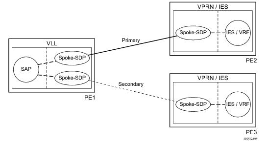
In Figure 97, PE1 terminates two spoke-SDPs that are bound to one SAP connected to CE1. PE1 chooses to forward traffic on one of the spoke SDPs (the active spoke-SDP), while blocking traffic on the other spoke-SDP (the standby spoke-SDP) in the transmit direction. PE2 and PE3 take any spoke-SDPs for which PW forwarding standby has been signaled by PE1 to an operationally down state.
Note that 7x50, 7710 routers are expected to fulfill both functions (VLL and VPRN/IES PE), while the 7705 must be able to fulfill the VLL PE function. Figure 98 illustrates the model for spoke-SDP redundancy into a VPRN or IES.
Figure 98: Spoke-SDP Redundancy Model
 
IP-VPNs
 
Using OSPF in IP-VPNs
Using OSPF as a CE to PE routing protocol allows OSPF that is currently running as the IGP routing protocol to migrate to an IP-VPN backbone without changing the IGP routing protocol, introducing BGP as the CE-PE or relying on static routes for the distribution of routes into the service providers IP-VPN. The following features are supported:
 
IPCP Subnet Negotiation
This feature enables negotiation between Broadband Network Gateway (BNG) and customer premises equipment (CPE) so that CPE is allocated both ip-address and associated subnet.
Some CPEs use the network up-link in PPPoE mode and perform dhcp-server function for all ports on the LAN side. Instead of wasting 1 subnet for p2p uplink, CPEs use allocated subnet for LAN portion as shown in Figure 99.
Figure 99: CPEs Network Up-link Mode
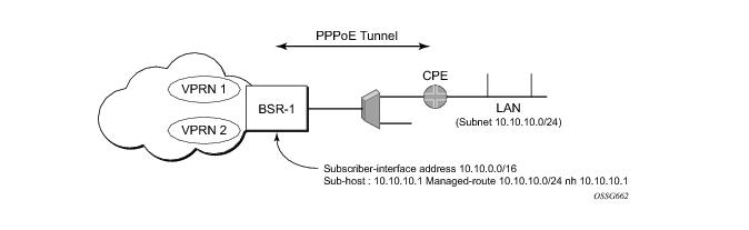
From a BNG perspective, the given PPPoE host is allocated a subnet (instead of /32) by RADIUS, external dhcp-server, or local-user-db. And locally, the host is associated with managed-route. This managed-route will be subset of the subscriber-interface subnet, and also, subscriber-host ip-address will be from managed-route range. The negotiation between BNG and CPE allows CPE to be allocated both ip-address and associated subnet.
 
Cflowd for IP-VPNs
The cflowd feature allows service providers to collect IP flow data within the context of a VPRN. This data can used to monitor types and general proportion of traffic traversing an VPRN context. This data can also be shared with the VPN customer to see the types of traffic traversing the VPN and use it for traffic engineering.
This feature should not be used for billing purposes. Existing queue counters are designed for this purpose and provide very accurate per bit accounting records.
 
 
Multicast in IP-VPN Applications
This section and its subsections focuses on Multicast in IP VPN functionality. A reader should familiarize itself first with Multicast section in SROS Routing Protocols Guide where multicast protocols (PIM, IGMP, MLD, MSDP) are described.
Applications for this feature include enterprise customer implementing a VPRN solution for their WAN networking needs, customer applications including stock-ticker information, financial institutions for stock and other types of trading data and video delivery systems.
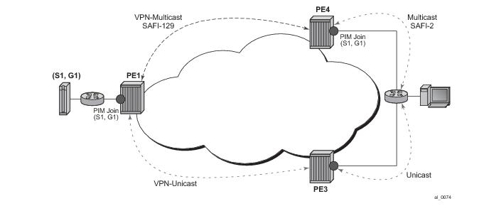
Implementation of the draft-rosen-vpn-mcast, Multicast in MPLS/BGP IP VPNs, entails the support and separation of the providers core multicast domain from the various customer multicast domains and the various customer multicast domains from each other.
Figure 100: Multicast in IP-VPN Applications
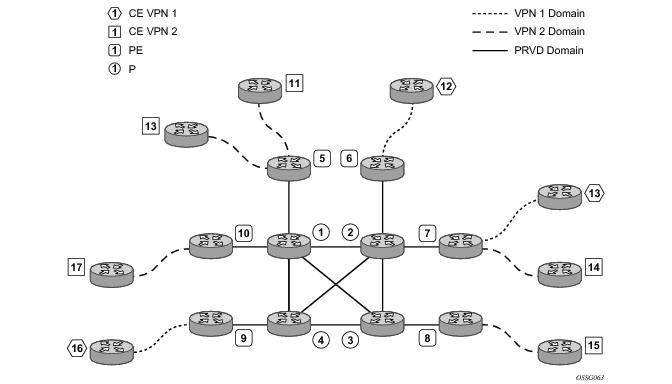
Figure 100 depicts an example of multicast in an IP-VPN application. The provider’s domain encompasses the core routers (1 through 4) and the edge routers (5 through 10). The various IP-VPN customers each have their own multicast domain, VPN-1 (CE routers 12, 13 and 16) and VPN-2 (CE Routers 11, 14, 15, 17 and 18). Multicast in this VPRN example, the VPN-1 data generated by the customer behind router 16 will be multicast only by PE 9 to PE routers 6 and 7 for delivery to CE routers 12 and 13 respectively. Data generated for VPN-2 generated by the customer behind router 15 will be forwarded by PE 8 to PE routers 5, 7 and 10 for delivery to CE routers 18, 11, 14 and 17 respectively.
The demarcation of these domains is in the PE’s (routers 5 through 10). The PE router participates in both the customer multicast domain and the provider’s multicast domain. The customer’s CEs are limited to a multicast adjacency with the multicast instance on the PE specifically created to support that specific customer’s IP-VPN. This way, customers are isolated from the provider’s core multicast domain and other customer multicast domains while the provider’s core routers only participate in the provider’s multicast domain and are isolated from all customers’ multicast domains.
The PE for a given customer’s multicast domain becomes adjacent to the CE routers attached to that PE and to all other PE’s that participate in the IP-VPN (or customer) multicast domain. This is achieved by the PE who encapsulates the customer multicast control data and multicast streams inside the provider’s multicast packets. These encapsulated packets are forwarded only to the PE nodes that are attached to the same customer’s edge routers as the originating stream and are part of the same customer VPRN. This prunes the distribution of the multicast control and data traffic to the PEs that participate in the customer’s multicast domain. The Rosen draft refers to this as the default multicast domain for this multicast domain; the multicast domain is associated with a unique multicast group address within the provider’s network.
 
 
Use of Data MDTs
Using the above method, all multicast data offered by a given CE is always delivered to all other CEs that are part of the same multicast. It is possible that a number of CEs do not require the delivery of a particular multicast stream because they have no downstream receivers for a specific multicast group. At low traffic volumes, the impact of this is limited. However, at high data rates this could be optimized by devising a mechanism to prune PEs from the distribution tree that although forming part of the customer multicast have no need to deliver a given multicast stream to the CE attached to them. To facilitate this optimization, the Rosen draft specifies the use of data MDTs. These data MDTs are signaled once the bandwidth for a given SG exceeds the configurable threshold.
Once a PE detects it is transmitting data for the SG in excess of this threshold, it sends an MDT join TLV (at 60 second intervals) over the default MDT to all PEs. All PEs that require the SG specified in the MDT join TLV will join the data MDT that will be used by the transmitting PE to send the given SG. PEs that do not require the SG will not join the data MDT, thus pruning the multicast distribution tree to just the PEs requiring the SG. After providing sufficient time for all PEs to join the data MDT, the transmitting PE switches the given multicast stream to the data MDT.
PEs that do not require the SG to be delivered, keep state to allow them to join the data MDT as required.
When the bandwidth requirement no longer exceeds the threshold, the PE stops announcing the MDT join TLV. At this point the PEs using the data MDT will leave this group and transmission resumes over the default MDT.
Sampling to check if an s,g has exceeded the threshold occurs every ten seconds. If the rate has exceeded the configured rate in that sample period then the data MDT is created. If during that period the transmission rate has not exceeded the configured threshold then the data MDT is not created. If the data MDT is active and the transmission rate in the last sample period has not exceeded the configured rate then the data MDT is torn down and the multicast stream resumes transmission over the default MDT.
 
Multicast Protocols Supported in the Provider Network
When MVPN auto-discovery is disabled, PIM-SM can be used for I-PMSI, and PIM-SSM or PIM-SM (Draft-Rosen Data MDT) can be used for S-PMSI; When MVPN S-PMSI auto-discovery is enabled, both PIM-SM and PIM SSM can be used for I-PMSI, and PIM-SSM can be used for S-PMSI. In the customer network, both PIM-SM and PIM-SSM are supported.
An MVPN is defined by two sets of sites: sender sites set and receiver sites set, with the following properties:
A site could be both in the sender sites set and receiver sites set, which implies that hosts within such a site could both originate and receive multicast traffic. An extreme case is when the sender sites set is the same as the receiver sites set, in which case all sites could originate and receive multicast traffic from each other.
Sites within a given MVPN may be either within the same, or in different organizations, which implies that an MVPN can be either an intranet or an extranet. A given site may be in more than one MVPN, which implies that MVPNs may overlap. Not all sites of a given MVPN have to be connected to the same service provider, which implies that an MVPN can span multiple service providers.
Another way to look at MVPN is to say that an MVPN is defined by a set of administrative policies. Such policies determine both sender sites set and receiver site set. Such policies are established by MVPN customers, but implemented by MVPN service providers using the existing BGP/MPLS VPN mechanisms, such as route targets, with extensions, as necessary.
 
MVPN Using BGP Control Plane
Note that the next generation MVPN solution replaces the Rosen MVPN draft and is currently being defined at the IETF. Its IETF status is still a working group draft but it has strong support. It is quite stable for implementation from a technical point of view.


The Alcatel-Lucent implementation supports the following features:
 
MVPN Membership Auto-discovery using BGP
BGP-based auto-discovery is performed by an multicast VPN address family. Any PE that attaches to an MVPN must issue a BGP update message containing an NLRI in this address family, along with a specific set of attributes.
The PE router uses route targets to specify MVPN route import and export. The route target may be the same as the one used for the corresponding unicast VPN, or it may be different. The PE router can specify separate import route targets for sender sites and receiver sites for a given MVPN.
The route distinguisher (RD) that is used for the corresponding unicast VPN can also be used for the MVPN.
When BGP auto-discovery is enabled, PIM peering on the I-PMSI is disabled, so no PIM hellos are sent on the I-PMSI. C-trees to P-tunnels bindings are also discovered using BGP S-PMSI AD routes, instead of PIM join TLVs. Configure PIM join TLVs when c-mcast-signaling is set to pim in the config>service>vprn>mvpn>provider-tunnel>selective>auto-discovery-disable context.
Table 26 and Table 27 describe the supported configuration combinations. If the CLI combination is not allowed, the system returns an error message. If the CLI command is marked as “ignored” in the table, the configuration is not blocked, but its value is ignored by the software.


For example, if auto-discovery is disabled, the c-mcast-signaling bgp command will fail with an error message stating:
C-multicast signaling in BGP requires auto-discovery to be enabled
If c-mcast-signaling is set to bgp then no auto-discovery will fail with an error message stating
C-multicast signaling in BGP requires auto-discovery to be enabled
When c-mcast-signaling is set to bgp, S-PMSI A-D is always enabled (its configuration is ignored);
When auto-discovery is disabled, S-PMSI A-D is always disabled (its configuration is ignored).
When auto-discovery is enabled and c-multicast-signaling is set to pim, S-PMSI A-D configuration value is used.
 
MVPN (Rosen) Membership Auto-Discovery using BGP MDT-SAFI
MVPN implementation based on the draft -Rosen can support membership auto discovery using BGP MDT-SAFI. A CLI option is provided per MVPN instance to enable auto discovery either using BGP MDT-SAFI or NG-MVPN. Only PIM-MDT is supported with BGP MDT-SAFI method.
 
PE-PE Transmission of C-Multicast Routing using BGP
MVPN c-multicast routing information is exchanged between PEs by using c-multicast routes that are carried using MCAST-VPN NLRI.
 
MVPN (NG-MVPN) Upstream Multicast Hop Fast Failover
MVPN upstream PE or P node fast failover detection method is supported with RSVP P2MP I-PMSI only. A receiver PE achieves fast upstream failover based on the capability to subscribe multicast flow from multiple UMH nodes and the capability to monitor the health of the upstream PE and intermediate P nodes using an unidirectional multi-point BFD session running over the provider tunnel.
A receiver PE subscribes multicast flow from multiple upstream PE nodes to have active redundant multicast flow available during failure of primary flow. Active redundant multicast flow from standby upstream PE allows instant switchover of multicast flow during failure of primary multicast flow.
Faster detection of multicast flow failure is achieved by keeping track of unidirectional multi-point BFD sessions enabled on the provider tunnel. Multi-point BFD sessions must be configured with 10 ms transmit interval on sender (root) PE to achieve sub-50ms fast failover on receiver (leaf) PE.
UMH tunnel-status selection option must be enabled on the receiver PE for upstream fast failover. Primary and standby upstream PE pairs must be configured on the receiver PE to allow receiving active redundant multicast flow from the standby upstream PE.
 
Provider Tunnel Support
The following provider tunnels features are supported:
 
Migration from Existing Rosen Implementation
The existing Rosen implementation is compatible to provide an easy migration path.
The following migration procedure are supported:
 
VRF Route Import Extended Community
VRF route import is an IP address-specific extended community, of an extended type, and is transitive across AS boundaries (RFC 4360, BGP Extended Communities Attribute.
To support MVPN, in addition to the import/export route target extended communities used by the unicast routing, each VRF on a PE must have an import route target extended community that controls imports of C-multicast routes into a particular VRF.
The c-multicast import RT uniquely identifies a VRF, and is constructed as follows:
A PE that has sites of a given MVPN connected to it communicates the value of the c-multicast import RT associated with the VRF of that MVPN on the PE to all other PEs that have sites of that MVPN. To accomplish this, a PE that originates a (unicast) route to VPN-IP addresses includes in the BGP updates message that carries this route the VRF route import extended community that has the value of the c-multicast import RT of the VRF associated with the route, except if it is known a priori that none of these addresses will act as multicast sources and/or RP, in which case the (unicast) route need not carry the VRF Route Import extended community.
All c-multicast routes with the c-multicast import RT specific to the VRF must be accepted. In this release, vrf-import and vrftraget policies don’t apply to C-multicast routes.
The decision flow path is shown below.
 if (route-type == c-mcast-route)
  if (route_target_list includes C-multicast_Import_RT){
   else
    drop;
  else
  Run vrf_import and/or vrf-target;
 
Point-to-Multipoint Inclusive (I-PMSI) and Selective (S-PMSI) Provider Multicast Service Interface
BGP c-multicast-signaling must be enabled for an MVPN instance to use P2MP RSVP-TE or LDP as I-PMSI (equivalent to ‘Default MDT’, as defined in draft Rosen MVPN) and S-PMSI (equivalent to ‘Data MDT’, as defined in draft Rosen MVPN).
By default, all PE nodes participating in MVPN receive data traffic over I-PMSI. Optionally, S-PMSI can be used for sending traffic to PE nodes that have at least one an active receiver connected to them for efficient data traffic distribution (Refer section: ‘Use of Data MDT’ for further details).
Only one unique multicast flow is supported over each P2MP RSVP-TE or P2MP LDP LSP S-PMSI. Number of S-PMSI that can be initiated per MVPN instance is restricted by CLI command maximum-p2mp-spmsi. P2MP LSP S-PMSI cannot be used for more than one (S,G) stream (that is, multiple multicast flow) as number of S-PMSI per MVPN limit is reached. Multicast flows that cannot switch to S-PMSI remain on I-PMSI.
 
P2MP RSVP-TE I-PMSI and S-PMSI
Point-to-Multipoint RSVP-TE LSP as inclusive or selective provider tunnel is available with BGP NG-MVPN only. P2MP RSVP-TE LSP is dynamically setup from root node on auto discovery of leaf PE nodes that are participating in multicast VPN. Each RSVP-TE I-PMSI or S-PMSI LSP can be used with a single MVPN instance only.
RSVP-TE LSP template must be defined (see MPLS user guide) and bound to MVPN as inclusive or selective (S-PMSI is for efficient data distribution and is optional) provider tunnel to dynamically initiate P2MP LSP to the leaf PE nodes learned via NG-MVPN auto-discovery signaling. Each P2MP LSP S2L is signaled based on parameters defined in LSP template.
 
P2MP LDP I-PMSI and S-PMSI
Point-to-Multipoint LDP LSP as inclusive or selective provider tunnel is available with BGP NG-MVPN only. P2MP LDP LSP is dynamically setup from leaf nodes on auto discovery of leaf node PE nodes that are participating in multicast VPN. Each LDP I-PMSI or S-PMSI LSP can be used with a single MVPN instance only.
‘multicast-traffic’ CLI command must be configured per LDP interface to enable P2MP LDP setup. P2MP LDP must also be configured as inclusive or selective (S-PMSI is for efficient data distribution and is optional) provider tunnel per MVPN to dynamically initiate P2MP LSP to leaf PE nodes learned via NG-MVPN auto-discovery signaling.
P2MP LSP S-PMSI
NG-MVPN has been extended to allow using P2MP RSVP-TE and P2MP LDP LSP as selective-provider multicast service interface (S-PMSI). S-PMSI is used in case to avoid sending traffic to PE node that just participates in multicast VPN but does not have any receivers for the multicast flow. This allows efficient distribution of multicast traffic over provider network, specifically for high bandwidth multicast flows. S-PMSI is spawned dynamically based on configured traffic bandwidth threshold for a range of multicast flows.
In MVPN, the head-end PE firstly discovers all the leaf PEs via I-PMSI A-D routes. It then signals the P2MP LSP to all the leaf PEs using RSVP-TE. In the scenario of S-PMSI:
1.
2.
3.
Also, because the receivers may come and go, the implementation supports dynamically adding and pruning leaf nodes to/from the P2MP LSP.
When the tunnel type in the PMSI attribute is set to RSVP-TE P2MP LSP, the Tunnel Identifier is <Extended Tunnel ID, Reserved, Tunnel ID, P2MP ID> as carried in the RSVP-TE P2MP LSP SESSION Object.
PE can also learn via an A-D route that it needs to receive traffic on a particular RSVP-TE P2MP LSP before the LSP is actually setup. In this case, the PE needs to wait until the LSP is operational before it can modify its forwarding tables as directed by the A-D route.
Because of the way that LDP normally works, mLDP P2MP LSPs are setup unsolicitly from the leaf PEs towards the head-end PE. The leaf PE discovers the head-end PE via I-PMSI/S-PMSI A-D routes. The Tunnel Identifier carried in the PMSI attribute is used as the P2MP FEC Element. The Tunnel Identifier consists of the head-end PE’s address, along with a Generic LSP Identifier value. The Generic LSP Identifier value is automatically generated by the head-end PE.
 
MVPN Sender-only/Receiver-only
In multicast MVPN, by default, if multiple PE nodes form a peering with a common MVPN instance then each PE node originates a multicast tree locally towards the remaining PE nodes that are member of this MVPN instance. This behavior creates a mesh of I-PMSI across all PE nodes in the MVPN. It is often a case, that a given VPN has many sites that will host multicast receivers, but only few sites that either host both receivers and sources or sources only.
MVPN Sender-only/Receiver-only allows to optimize control and data plane resources by preventing unnecessary I-PMSI mesh when a given PE hosts multicast sources only or multicast receivers only for a given MVPN.
For PE nodes that host only multicast sources for a given VPN, operators can now block those PEs, through configuration, from joining I-PMSIs from other PEs in this MVPN. For PE nodes that host only multicast receivers for a given VPN, operators can now block those PEs, through configuration, to set-up a local I-PMSI to other PEs in this MVPN.
MVPN Sender-only/Receiver-only is supported with ng-mVPN using IPv4 RSVP-TE or IPv4 LDP provider tunnels for both IPv4 and IPv6 customer multicast. Figure 101 depicts 4-site MVPN with sender-only, receiver-only and sender-receiver (default) sites:
Figure 101: MVPN Sender-only/Receiver-only Example
Aa extra attention needs to be placed to BSR/RP placement when Sender-only/Receiver-only is enabled. Source DR sends unicast encapsulated traffic towards RP, therefore, RP shall be at sender-receiver or sender-only site, so that *G traffic can be sent over the tunnel. BSR shall be deployed at the sender-receiver site. BSR can be at sender-only site if the RPs are at the same site. BSR needs to receive packets from other candidate-BSR and candidate-RPs and also needs to send BSM packets to everyone.
 
Multicast VPN Extranet
Multicast VPN extranet distribution allows multicast traffic to flow across VPRN instances. VPRN instance that received a PIM/IGMP JOIN but cannot reach source of multicast source directly within its VPRN is selected as receiver VPRN instance. VPRN instance that has source of multicast stream and accepts PIM/IGMP JOIN from other VPRN instances is selected as source VPRN instance.
Routing information is exchanged between source and receiver VPRN instances of extranet based on route import/export policies. Routing information for multicast source in source VPRN instance is exported using RT export policy. Routing information for multicast source is imported in receiver VPRN instance using RT import policy.
Multicast receiver host in a receiver VPRN instance of extranet can subscribe to stream from a multicast source node reachable via source VPRN instance of extranet. Source VPRN instance and receiver VPRN instance of extranet must exist on a common PE node. PIM/IGMP JOIN received in a VPRN instance is propagated to source VPRN instance based on routing information.
 
Figure 102: Multicast VPN Traffic Flow
 
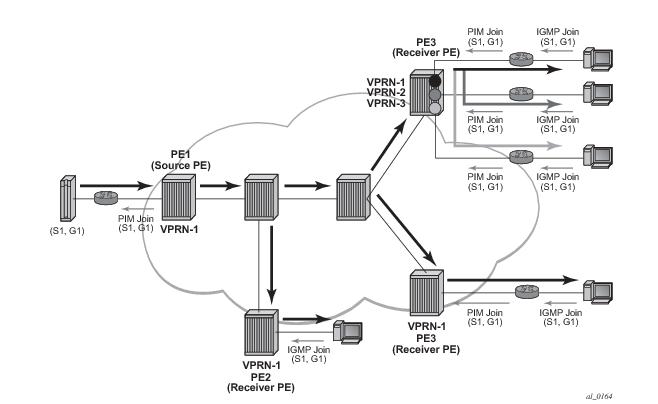
In Figure 102, VPRN-1 is source VPRN instance. VPRN-2 and VPRN-3 are receiver VPRN instances. PIM/IGMP JOIN received on VPRN-2 or VPRN-3 is for (S1,G1) multicast flow. Source S1 belongs to VPRN-1. Due to route export policy in VPRN-1 and import policy in VPRN-2 and VPRN-3, receiver host in VPRN-2 or VPRN-3 can subscribe to stream (S1,G1).
Multicast VPN extranet based on draft Rosen (MDT-SAFI) is supported. Only PIM-SSM is supported for extranet multicast distribution.
 
Non-Congruent Unicast and Multicast Topologies for Multicast VPN
Operators that prefer to keep unicast and multicast traffic on separate links in network have option to maintain two separate instances of route table (unicast and multicast) per VPRN.
Multicast BGP can be used to advertise separate multicast routes using Multicast NLRI (SAFI 2) on PE-CE link within VPRN instance. Multicast routes maintained per VPRN instance can be propagated between PE-PE using BGP Multicast-VPN NLRI (SAFI 129).
Figure 103: Incongruent Multicast and Unicast Topology for Non-Overlapping Traffic Links
SR-OS supports option to perform RPF check per VPRN instance using multicast route table, unicast route table or both.
Non-congruent unicast and multicast topology is supported with NG-MVPN. Draft Rosen is not supported.
 
IPv6 MVPN Support
IPv6 multicast support in SROS allows operators to offer customers IPv6 multicast MVPN service. An operator utilizes IPv4 mLDP or RSVP-TE core to carry IPv6 c-multicast traffic inside IPv4 mLDP or RSVPE-TE provider tunnels (p-tunnels). The IPv6 customer multicast on a given MVPN can be blocked, enabled on its own or in addition to IPv4 multicast per PE or per interface. When both IPv4 and IPv6 multicast is enabled for a given MVPN, a single tree is used to carry both IPv6 and IPv4 traffic. Figure 104 shows an example of an operator with IPv4 MPLS backbone providing IPv6 MVPN service to Customer 1 and Customer 2.
Figure 104: IPv6 MVPN Example
SROS IPv6 MVPN multicast implementation provides the following functionality:
The following known caveats exist for IPv6 MVPN support:
1.
2.
3.
4.
5.
 
Inter-AS MVPN
The Inter-AS MVPN feature allows set-up of Multicast Distribution Trees (MDTs) that span multiple Autonomous Systems (ASes). See Chapter , Virtual Private Routed Network Service section of this guide for background on Inter-AS VPN support in SROS. This section focuses on multicast aspects of the Inter-AS MVPN solution.
To support Inter-AS option for MVPNs, a mechanism is required that allows setup of Inter-AS multicast tree across multiple ASes. Due to limited routing information across AS domains, it is not possible to setup the tree directly to the source PE. Inter-AS VPN Option A does not require anything specific to inter-AS support as customer instances terminate on ASBR and each customer instance is handed over to the other AS domain via a unique instance. This approach allows operators to provide full isolation of ASes, but the solution is the least scalable case, as customer instances across the network have to exist on ASBR.
Inter-AS MVPN Option B allows operators to improve upon the Option A scalability while still maintaining AS isolation, while Inter-AS MVPN option C further improves Inter-AS scale solution but requires exchange of Inter-AS routing information and thus is typically deployed when a common management exists across all ASes involved in the Inter-AS MVPN. The following sub-sections provide further details on Inter-AS Option B and Option C functionality.
 
BGP Connector Attribute
BGP connector attribute is a transitive attribute (unchanged by intermediate BGP speaker node) that is carried with VPNv4 advertisements. It specifies the address of source PE node that originated the VPNv4 advertisement.
With Inter-AS MVPN Option B, BGP next-hop is modified by local and remote ASBR during re-advertisement of VPNv4 routes. On BGP next-hop change, information regarding the originator of prefix is lost as the advertisement reaches the receiver PE node.
BGP connector attribute allows source PE address information to be available to receiver PE, so that a receiver PE is able to associate VPNv4 advertisement to the corresponding source PE.
 
PIM RPF Vector
In case of Inter-AS MVPN Option B, routing information towards the source PE is not available in a remote AS domain, since IGP routes are not exchanged between ASes. Routers in an AS other than that of a source PE, have no routes available to reach the source PE and thus PIM JOINs would never be sent upstream. To enable setup of MDT towards a source PE, BGP next-hop (ASBR) information from that PE's MDT-SAFI advertisement is used to fake a route to the PE. If the BGP next-hop is a PIM neighbor, the PIM JOINs would be sent upstream. Otherwise, the PIM JOINs would be sent to the immediate IGP next-hop (P) to reach the BGP next-hop. Since the IGP next-hop does not have a route to source PE, the PIM JOIN would not be propagated forward unless it carried extra information contained in RPF Vector.
In case of Inter-AS MVPN Option C, unicast routing information towards the source PE is available in a remote AS PEs/ASBRs as BGP 3107 tunnels, but unavailable at remote P routers. If the tunneled next-hop (ASBR) is a PIM neighbor, the PIM JOINs would be sent upstream. Otherwise, the PIM JOINs would be sent to the immediate IGP next-hop (P) to reach the tunneled next-hop. Since the IGP next-hop does not have a route to source PE, the PIM JOIN would not be propagated forward unless it carried extra information contained in RPF Vector.
To enable setup of MDT towards a source PE, PIM JOIN thus carries BGP next hop information in addition to source PE IP address and RD for this MVPN. For option-B, both these pieces of information are derived from MDT-SAFI advertisement from the source PE. For option-C, both these pieces of information are obtained from the BGP tunneled route.
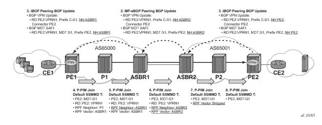
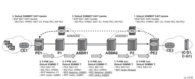
The RPF vector is added to a PIM join at a PE router when configure router pim rpfv option is enabled. P routers and ASBR routers must also have the option enabled to allow RPF Vector processing. If the option is not enabled, the RPF Vector is dropped and the PIM JOIN is processed as if the PIM Vector were not present.
For further details about RPF Vector processing please refer to [RFCs 5496, 5384 and 6513]
 
Inter-AS MVPN Option B
Inter-AS Option B is supported for Rosen MVPN PIM SSM using BGP MDT SAFI, PIM RPF Vector and BGP Connector attribute. The Figure 105 depict set-up of a default MDT:
Figure 105: Inter-AS Option B Default MDT Setup
SROS inter-AS Option B is designed to be standard compliant based on the following RFCs:
The SROS implementation was designed also to interoperate with older routers Inter-AS implementations that do not comply with the RFC 5384 and RFC 5496.
 
Inter-AS MVPN Option C
Inter-AS Option C is supported for Rosen MVPN PIM SSM using BGP MDT SAFI and PIM RPF Vector. Figure 106 depicts a default MDT setup:
Figure 106: Inter-AS Option C Default MDT Setup
These caveats apply to inter-AS option B and option C. Maybe we have them as a separate subsection (same level as any subsection of inter-AS MVPN section)?
Additional caveats for Inter-AS MVPN Option B and C support:
1.
2.
3.
The SROS implementation was designed to interoperate with Cisco routers Inter-AS implementations that do not comply with the RFC5384 and RFC5496.
When configure router pim rpfv mvpn option is enabled, Cisco routers need to be configured to include RD in an RPF vector using the following command: ip multicast vrf vrf-name rpf proxy rd vector for interoperability When Cisco routers are not configured to include RD in an RPF vector, operator should configure SROS router (if supported) using configure router pim rpfv core mvpn: PIM joins received can be a mix of core and mvpn RPF vectors.
 
 
Inter-AS VPRNs
Inter-AS IP-VPN services have been driven by the popularity of IP services and service provider expansion beyond the borders of a single Autonomous System (AS) or the requirement for IP VPN services to cross the AS boundaries of multiple providers. Three options for supporting inter-AS IP-VPNs are described in RFC 4364, BGP/MPLS IP Virtual Private Networks (VPNs).
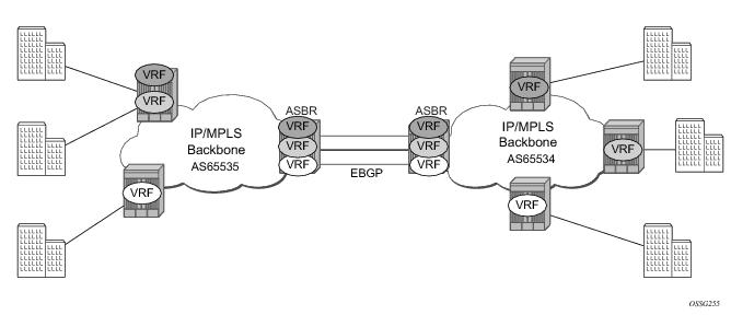
The first option, referred to as Option-A (Figure 107), is considered inherent in any implementation. This method uses a back-to-back connection between separate VPRN instances in each AS. As a result, each VPRN instance views the inter-AS connection as an external interface to a remote VPRN customer site. The back-to-back VRF connections between the ASBR nodes require individual sub-interfaces, one per VRF.
 
Figure 107: Inter-AS Option-A: VRF-to-VRF Model
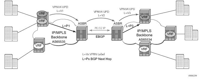
The second option, referred to as Option-B (Figure 108), relies heavily on the AS Boundary Routers (ASBRs) as the interface between the autonomous systems. This approach enhances the scalability of the eBGP VRF-to-VRF solution by eliminating the need for per-VPRN configuration on the ASBR(s). However it requires that the ASBR(s) provide a control plan and forwarding plane connection between the autonomous systems. The ASBR(s) are connected to the PE nodes in its local autonomous system using iBGP either directly or through route reflectors. This means the ASBR(s) receive all the VPRN information and will forward these VPRN updates, VPN-IPV4, to all its EBGP peers, ASBR(s), using itself as the next-hop. It also changes the label associated with the route. This means the ASBR(s) must maintain an associate mapping of labels received and labels issued for those routes. The peer ASBR(s) will in turn forward those updates to all local IBGP peers.
Figure 108: Inter-AS Option-B
This form of inter-AS VPRNs does not require instances of the VPRN to be created on the ASBR, as in option-A, as a result there is less management overhead. This is also the most common form of Inter-AS VPRNs used between different service providers as all routes advertised between autonomous systems can be controlled by route policies on the ASBRs by the config>router>bgp>transport-tunnel CLI command.
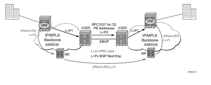
The third option, referred to as Option-C (Figure 109), allows for a higher scale of VPRNs across AS boundaries but also expands the trust model between ASNs. As a result this model is typically used within a single company that may have multiple ASNs for various reasons.
This model differs from Option-B, in that in Option-B all direct knowledge of the remote AS is contained and limited to the ASBR. As a result, in option-B the ASBR performs all necessary mapping functions and the PE routers do not need perform any additional functions then in a non-Inter-AS VPRN.
Figure 109: Option C Example
With Option-C, knowledge from the remote AS is distributed throughout the local AS. This distribution allows for higher scalability but also requires all PEs and ASBRs involved in the Inter-AS VPRNs to participate in the exchange of inter-AS routing information.
In Option-C, the ASBRs distribute reachability information for remote PE’s system IP addresses only. This is done between the ASBRs by exchanging MP-eBGP labeled routes, using RFC 3107, Carrying Label Information in BGP-4 . Either RSVP-TE or LDP LSP can be selected to resolve next-hop for multi-hop eBGP peering by the config>router>bgp>transport-tunnel CLI command.
Distribution of VPRN routing information is handled by either direct MP-BGP peering between PEs in the different ASNs or more likely by one or more route reflectors in ASN.
 
Carrier Supporting Carrier (CsC)
Carrier Supporting Carrier (CSC) is a solution that allows one service provider (the “Customer Carrier”) to use the IP VPN service of another service provider (the “Super Carrier”) for some or all of its backbone transport. RFC 4364 defines a Carrier Supporting Carrier solution for BGP/MPLS IP VPNs that uses MPLS on the interconnections between the two service providers in order to provide a scalable and secure solution.
CsC support in SROS allows a 7x50 to be deployed as any of the following devices shown in Figure 110:
Figure 110: Carrier Supporting Carrier Reference Diagram
 
Terminology
CE — Customer premises equipment dedicated to one particular business/enterprise.
PE — Service provider router that connects to a CE to provide a business VPN service to the associated business/enterprise.
CSC-CE — An ASBR/peering router that is connected to the CSC-PE of another service provider for purposes of using the associated CsC IP VPN service for backbone transport.
CSC-PE — A PE router belonging to the backbone service provider that supports one or more CSC IP VPN services.
 
CSC Connectivity Models
A PE router deployed by a customer service provider to provide Internet access, IP VPNs, and/or L2 VPNs may connect directly to a CSC-PE device, or it may back haul traffic within its local “site” to the CSC-CE that provides this direct connection. Here, “site” means a set of routers owned and managed by the customer service provider that can exchange traffic through means other than the CSC service. The function of the CSC service is to provide IP/MPLS reachability between isolated sites.
The CSC-CE is a “CE” from the perspective of the backbone service provider. There may be multiple CSC-CEs at a given customer service provider site and each one may connect to multiple CSC-PE devices for resiliency/multi-homing purposes.
The CSC-PE is owned and managed by the backbone service provider and provides CSC IP VPN service to connected CSC-CE devices. In many cases, the CSC-PE also supports other services, including regular business IP VPN services. A single CSC-PE may support multiple CSC IP VPN services. Each customer service provider is allocated its own VRF within the CSC-PE; VRFs maintain routing and forwarding separation and permit the use of overlapping IP addresses by different customer service providers.
A backbone service provider may not have the geographic span to connect, with reasonable cost, to every site of a customer service provider. In this case, multiple backbone service providers may coordinate to provide an inter-AS CSC service. Different inter-AS connectivity options are possible, depending on the trust relationships between the different backbone service providers.
 
CSC-PE Configuration and Operation
This section applies to CSC-PE1, CSC-PE2 and CSC-PE3 in Figure 110 .
 
CSC Interface
From the point of view of the CSC-PE, the IP/MPLS interface between the CSC-PE and a CSC-CE has these characteristics:
1.
2.
3.
4.
5.
6.
7.
8.
CSC interfaces are only supported on Ethernet ports and LAGs residing on FP2 or better cards and systems. An Ethernet port or LAG with a CSC interface can be configured in hybrid mode or network mode. The port or LAG supports null, dot1q or qinq encapsulation. To create a CSC interface on a port or LAG in null mode, the following commands are used:
config>service>vprn>network-interface>port port-id
config>service>vprn>network-interface>lag lag-id
To create a CSC interface on a port or LAG in dot1q mode, the following commands are used:
config>service>vprn>network-interface>port port-id:qtag1
config>service>vprn>network-interface>lag port-id:qtag1
 
To create a CSC interface on a port or LAG in qinq mode, the following commands are used:
config>service>vprn>network-interface>port port-id:qtag1.qtag2
config>service>vprn>network-interface>port port-id:qtag1.*
config>service>vprn>network-interface>lag port-id:qtag1.qtag2
config>service>vprn>network-interface>lag port-id:qtag1.*
 
A CSC interface supports the same capabilities (and supports the same commands) as a base router network interface except it does not support:
 
QoS
Egress
Egress traffic on a CSC interface can be shaped and scheduled by associating a port-based egress queue-group instance with the CSC interface. The steps for doing this are summarized below:
1.
2.
3.
4.
5.
6.
7.
Ingress
Ingress traffic on a CSC interface can be policed by associating a forwarding-plane based ingress queue-group instance with the CSC interface. The steps for doing this are summarized below:
1.
2.
3.
4.
5.
6.
7.
MPLS
BGP-3107 is used as the label distribution protocol on the CSC interface. When BGP in a CSC VPRN needs to distribute a label corresponding to a received VPN-IPv4 route, it takes the label from the global label space. The allocated label will not be re-used for any other FEC regardless of the routing instance (base router or VPRN). If a label L is advertised to the BGP peers of CSC VPRN A then a received packet with label L as the top most label is only valid if received on an interface of VPRN A, otherwise the packet is discarded.
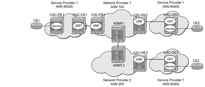
To use BGP-3107 as the label distribution protocol on the CSC interface, add the advertise-label ipv4 command to the BGP neighbor configuration. This command causes the capability to send and receive labeled-IPv4 routes {AFI=1, SAFI=4} to be negotiated with the CSC-CE peers.
 
CSC VPRN Service Configuration
To configure a VPRN to support CSC service, the carrier-carrier-vpn command must be enabled in its configuration. The command will fail if the VPRN has any existing SAP or spoke-SDP interfaces. A CSC interface can be added to a VPRN (using the network-interface command) only if the carrier-carrier-vpn command is present.
A VPRN service with the carrier-carrier-vpn command may be provisioned to use auto-bind, configured spoke SDPs or some combination. All SDP types are supported except for:
• GRE SDPs
• LDP over RSVP-TE tunnel SDPs
Other aspects of VPRN configuration are the same in a CSC model as in a non-CSC model.
 
Traffic Leaking to GRT
Traffic leaking to Global Route Table (GRT) allows service providers to offer VPRN and Internet services to their customers over a single VRF interface. This currently supports IPv4 and requires the customer VRPN interfaces to terminate on a minimum of IOM3-XP and IMM hardware. It is also supported on the 7750 SR-C12.
Packets entering a local VRF interface can have route processing results derived from the VPRN forwarding table or the GRT. The leaking and preferred lookup results are configured on a per VPRN basis. Configuration options can be general (for example, any lookup miss in the VRPN forwarding table can be resolved in the GRT), or specific (for example, specific route(s) should only be looked up in the GRT and ignored in the VPRN). In order to provide operational simplicity and improve streamlining, the CLI configuration is all contained within the context of the VPRN service.
This feature is enabled within the VPRN service context under config>service>vprn>grt-lookup. This is an administrative context and provides the container under which all specific commands can be entered, except for policy definition. Policy definitions remain unchanged but are referenced from this context.
The enable-grt command establishes the basic functionality. When it is configured, any lookup miss in the VRF table will be resolved in the GRT, if available. By itself, this only provides part of the solution. Packet forwarding within GRT must understand how to route packets back to the proper node and to the specific VPRN from which the destination exists. Destination prefixes must be leaked from the VPRN to the GRT through the use of policy. Policies are created under the config>router>policy-options hierarchy. By default, the number of prefixes leaked from the VPRN to the GRT is limited to five. The export-limit command under the grt-lookup hierarchy allows the service provider to override the default, or remove the limit.
When a VPRN forwarding table consists of a default route or an aggregate route, the customer may require the service provider to poke holes in those, or provide more specific route resolution in the GRT. In this case, the service provider may configure a “static-route”, under the “enable-grt” context. The lookup result will prefer any successful lookup in the GRT that is equal to or more specific than the static route, bypassing any successful lookup in the local VPRN.
This feature and Unicast Reverse Path Forwarding (uRPF) are mutually exclusive. When a VPRN service is configured with either of these functions, the other cannot be enabled. Also, prefixes leaked from any VPRN should never conflict with prefixes leaked from any other VPRN or existing prefixes in the GRT. Prefixes should be globally unique with the service provider network and if these are propagated outside of a single providers network, they must be from the public IP space and globally unique. Network Address Translation (NAT) is not supported as part of this feature.It is also important to note that aggregate routes, blackhole routes and BGP VPN extranet routes will not be leaked from the VPRN into the base routing table.
 
Traffic Leaking from VPRN to GRT for IPv6
This feature allows IPv6 destination lookups in two distinct routing tables. IPv6 packets within a Virtual Private Routed Network (VPRN) service is able to perform a lookup for IPv6 destination against the Global Route Table (GRT) as well as within the local VPRN.
Currently, VPRN to VPRN routing exchange is accomplished through the use of import and export policies based on Route Targets (RTs), the creation of extranets. This new feature allows the use of a single VPRN interface for both corporate VPRN routing and other services (for example, Internet) that are reachable outside the local routing context. This feature takes advantage of the dual lookup capabilities in two separate routing tables in parallel.
This feature enables IPv6 capability in addition to the existing IPv4 VPRN-to-GRT Route Leaking feature.
 
RIP Metric Propagation in VPRNs
When RIP is used as the PE-CE protocol for VPR Ns (IP-VPNs), the RIP metric is only used by the local node running RIP with the Customer Equipment (CE). The metric is not used to or encoded into and MP-BGP path attributes exchanged between PE routers.
The RIP metric can also be used to exchanged between PE routers so if a customer network is dual homed to separate PEs the RIP metric learned from the CE router can be used to choose the best route to the destination subnet. By using the learned RIP metric to se the BGP MED attribute, remote PEs can choose the lowest MED and in turn the PE with the lowest advertised RIP metric as the preferred egress point for the VPRN.
Figure 111: RIP Metric Propagation in VPRNs
 
NTP Within a VPRN Service
The NTP within a VPRN service enables the service router to act as the NTP server to CPE devices on a VPRN interface. Individual VPRN interfaces may be configured to listen to and respond to client requests, or additionally may be configured to send NTP broadcast messages. Authentication keys are configurable on a per-VPRN basis.
Only a single instance of NTP remains in the node that is time sourced to as many as five NTP servers attached to the “base” or “management” network.
The NTP show command displays NTP servers and all known clients. Because NTP is UDP based only, no state is maintained. As a result, the show command output only displays when the last message from the client was received.
Service Label Mode of a VPRN
The mode used for allocating service labels to VPN routes is now configurable per VPRN service. When the label mode is configured in the default per-VRF mode, the 7750-SR allocates one unique (platform-wide) service label per VRF. All VPN-IP routes exported by the PE from a particular VPRN service with that configuration have the same service label. When the PE receives a terminating MPLS packet, the service label value determines the VRF to which the packet belongs. A lookup of the IP packet DA in the forwarding table of the selected VRF determines the next-hop interface.
When, alternatively, a VPRN is configured in the new service label per next-hop mode, MPLS allocates one unique (platform-wide) service label per next-hop IP mode of the VPRN. All IP routes of the VPRN with a specific next-hop are advertised with the same service label value when exported as VPN-IP routes. When the PE receives a terminating MPLS packet and the service label value is associated with a VPRN next-hop address the IP packet is forwarded to that next-hop without any lookup of the IP packet DA in the VRF forwarding table.
 
Configuring the Service Label Mode
To change the service label mode of the VPRN the config>service>vprn>label-mode {vrf | next-hop} command is used:
The default mode (if the command is not present in the VPRN configuration) is vrf meaning distribution of one service label for all routes of the VPRN. When a VPRN X is configured with the label-mode next-hop command the service label that it distributes with an IPv4 or IPv6 route that it exports depends on the type of route as summarized in Table 28.
 
A change to the label-mode of a VPRN requires the VPRN to first be shutdown.
 
Restrictions and Usage Notes
The service label per next-hop mode has the following restrictions:
 
VPRN Off-Ramp
This feature enhances the operation and deployment options service providers will have with the TMS-ISA DDoS and threat mitigation.
To enhance the operational flexibility of the DDoS scrubbing capabilities supported by MS-ISA TMS, this section discusses support for VPRN off-ramp to MS-ISA Threat Management Server (TMS) adding to the GRT (Global Routing Table) off-ramp already supported.
The current deployment model works as follows:
1.
2. On-ramping of clean traffic — Once traffic is forwarded to the TMS-ISA, the attack traffic is separated from the legitimate traffic destined to the address or address range under attack, the “clean” traffic is forced into a clean VRF that must contain the original PE serving the IP under attack. The traffic is then tunneled (by LDP or GRE) to the originally intended PE where it can be routed to its destination.
This features offer the ability to off-ramp traffic directly from VPN context where MS-ISA TMS may communicate with may communicate with CPM to insert internal re-direct routes within specific VPNs used as either DDoS scrubbing VRFs (where an operator designates one or more VPRNs for carrying traffic to be scrubbed) or where the VPRN contains the global routes using the MPLS network to transport internet traffic.
In this case, rather than having the MS-ISA TMS trigger an internal re-direct route from GRT to one or more MS-ISA TMS instances, we allow the operator to configure a VPRN associated with carrying off-ramp traffic to be scrubbed so that prefixes under attack are added to that VPRN VRF ensuring traffic coming in on that VPN is off-ramped to MS-ISA TMS for scrubbing.
This model allows operational flexibility and simplicity where GRTs throughout the network do not need to be constantly changed for off-ramping of traffic, but instead off-ramp traffic can be isolated into a “dirty VRF” for cleaning after which it is returned to an unmodified global routing table or another operator defined VPN used for on-ramping clean traffic toward customers.
In addition, allowing VRF-based redirection to MS-ISA TMS provides a critical piece of a full flowspec directed DDoS scrubbing solution where flowspec policies are used to separate attack flows into “dirty VRF” where 7750 SRs running MS-ISA TMS scan then be configured to forward traffic from these DDoS VRFs to the TMS running on MS-ISA for scrubbing. Clean traffic would then be returned to the network by either a VPN or the GRT.
 
DDoS Off-Ramping Through Flowspec
Flowspec policy can be used to further simplify DDoS scrubbing architecture resulting in more scalable and operationally simplified topologies.
In this case, CP detectors will detect the destination under attack, including the flows (src/dest pairs) involved in the attack and either directly (or through interaction with an operator’s scripting engine) advertise flowspec extended BGP updates to peering and edge routers.
Peering/edge routes with flowspec enabled can redirect traffic to a VPN ensuring that traffic signaled for off-ramp by a CP is placed into a “dirty VPN” which will then be used to forward traffic to MS-ISA TMS for scrubbing.
Rather than altering the GRT table (as in the routed off-ramp model), flowspec policy allows granular policy redirection to take place to off-ramp VRF.
Since the GRT has not been altered, clean traffic is forwarded back to either a clean VRF or the GRT for routing to its originally intended destination.
Flowspec forwarding requires the IOM-3.
 
Multicast Auto RP Discovery
Auto-RP is a proprietary implementation of a protocol to dynamically learn about availability of Rendezvous Point (RP) in network. Auto-RP protocol consists of announcing, mapping and discovery functions. SROS only supports the discovery mode of Auto-RP that includes mapping and forwarding of RP-mapping and RP-candidate messages. Auto-RP support is only available with multicast VPN (NG-MVPN).