Note: Refer to the 7750 SR OS Triple Play Guide for information about how subscriber group-interfaces function in the Routed Central Office model.
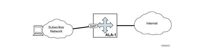
This section describes various of the general7750 SR service features and any special capabilities or considerations as they relate to IES services.
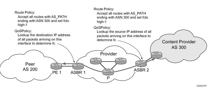
Figure 84 shows an example of an ISP that has an agreement with the content provider managing AS300 to provide traffic sourced and terminating within AS300 with differentiated service appropriate to the content being transported. In this example we presume that ASBR1 and ASBR2 mark the DSCP of packets terminating and sourced, respectively, in AS300 so that other nodes within the ISP’s network do not need to rely on QPPB to determine the correct forwarding-class to use for the traffic. Note however, that the DSCP or other COS markings could be left unchanged in the ISP’s network and QPPB used on every node.
The fc command is supported with all existing from and to match conditions in a route policy entry and with any action other than reject, it is supported with next-entry, next-policy and accept actions. If a next-entry or next-policy action results in multiple matching entries then the last entry with a QPPB action determines the forwarding class and priority.
A route policy that includes the fc command in one or more entries can be used in any import or export policy but the
fc command has no effect except in the following types of policies:
This feature uses a qos keyword to the
show>router>route-table command. When this option is specified the output includes an additional line per route entry that displays the forwarding class and priority of the route. If a route has no fc and priority information then the third line is blank. The following CLI shows an example:
To enable QoS classification of ingress IP packets on an interface based on the QoS information associated with the routes that best match the packets the qos-route-lookup command is necessary in the configuration of the IP interface. The
qos-route-lookup command has parameters to indicate whether the QoS result is based on lookup of the source or destination IP address in every packet. There are separate qos-route-lookup commands for the IPv4 and IPv6 packets on an interface, which allows QPPB to enabled for IPv4 only, IPv6 only, or both IPv4 and IPv6. Note however, current QPPB based on a source IP address is not supported for IPv6 packets nor is it supported for ingress subscriber management traffic on a group interface.
When QPPB is enabled on a SAP IP interface the forwarding class of a packet may change from fc1, the original
fc determined by the SAP ingress QoS policy to fc2, the new fc determined by QPPB. In the ingress datapath SAP ingress QoS policies are applied in the first P chip and route lookup/QPPB occurs in the second P chip. This has the implications listed below:
Table 14 summarizes these interactions.
In the 7750 SR OS, the accounting paradigm is based on sla-profile instances, yet this is at odds with traditional RADIUS authentication and accounting which is host-centric. In previous OS releases, it was possible to have many hosts sharing a common sla-profile instance, and thus accounting and QoS parameters. Complications would arise with RADIUS accounting because Accounting-Start and Accounting-Stop are a function of sla-profile instance and not the hosts – this meant that some host-specific parameters (like Framed-Ip-Address) would not be consistently included in RADIUS accounting.
A new command, host-accounting, is introduced under
accounting-policy, which allows configurable behavior.
When no host-accounting is configured, accounting behavior is as follows:
When host-accounting is configured, additional RADIUS accounting messages are created for host activity in addition to messages for common queue accounting. The behavior is as follows:
The 7750 SR series supports ATM PVC service encapsulation for IES SAPs. Both UNI and NNI cell formats are supported. The format is configurable on a SONET/SDH path basis. A path maps to an ATM VC. All VCs on a path must use the same cell format.
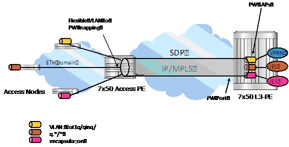
Figure 85 illustrates the architecture of an aggregation network that uses pseudowire SAPs.
Table 16 summarizes the default packet sizes used at each of the schedulers on the IOM/Ethernet MDA and HSMDAv2, assuming a 1000byte customer packet.
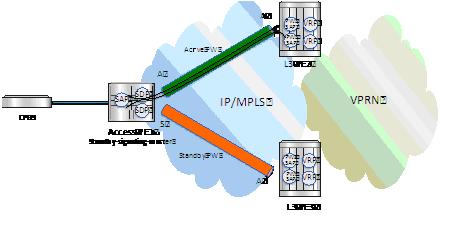
Dual homing operates in a similar manner to spoke-sdp termination on IES/VPRN. Figure 86 displays the access PE is dual-homed to the Layer 3 PEs using two spoke-SDPs. The endpoint in the access PE is configured to be the master from a pseudowire redundancy perspective using the standby-signaling-master command. The access PE picks one of the spoke-SDPs to make active, and one to make standby, based on the local configuration of primary or spoke SDP precedence.
When applied to 7750 SR IES services, service ingress QoS policies only create the unicast queues defined in the policy. The multipoint queues are not created on the service. With IES services, service egress QoS policies function as with other services where the class-based queues are created as defined in the policy. Note that both Layer 2 or Layer 3 criteria can be used in the QoS policies for traffic classification in an IES.
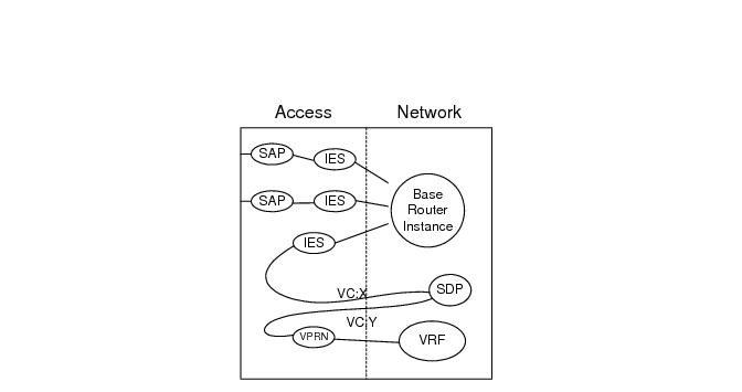
This feature provides the ability to cross-connect traffic entering on a spoke SDP, used for Layer 2 services (VLLs or VPLS), on to an IES or VPRN service. From a logical point of view, the spoke SDP entering on a network port is cross-connected to the Layer 3 service as if it entered by a service SAP. The main exception to this is traffic entering the Layer 3 service by a spoke SDP is handled with network QoS policies not access QoS policies.
Figure 87 depicts traffic terminating on a specific IES or VPRN service that is identified by the
sdp-id and VC label present in the service packet.
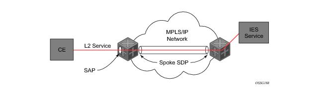
Figure 88 depicts a spoke SDP terminating directly into an IES. In this case, a spoke SDP could be tied to an Epipe or HVPLS service. There is no configuration required on the PE connected to the CE.
Table 17 lists the SRRP’s state effect on subscriber hosts associated with group IP interfaces.
SRRP advertisement messages carry a becoming-master indicator flag. The
becoming-master flag is set by a node that is attempting to usurp the master state from an existing SRRP master router. When receiving an SRRP advertisement message with a better priority and with the
becoming-master flag set, the local master initiates its
becoming-backup state, stops routing with the SRRP gateway MAC and sends an SRRP advertisement message with a priority set to zero. The new master continues to send SRRP advertisement messages with the
becoming-master flag set until it either receives a return priority zero SRRP advertisement message from the previous master or its
becoming-master state timer expires. The new backup node continues to send zero priority SRRP advertisement messages every time it receives an SRRP advertisement message with the
becoming-master flag set. After the new master either receives the old masters priority zero SRRP advertisement message or the
become-master state timer expires, it enters the
master state. The
become-master state timer is set to 10 seconds upon entering the
become-master state.
The SRRP instance maintains the source IP address of the current master. If an advertisement is received with the current masters source IP address and the local priority is higher priority than the masters advertised priority, the local node immediately enters the becoming-master state unless the advertised priority is zero. If the advertised priority is zero, the local node bypasses the
becoming-master state and immediately enters the
master state. Priority zero is a special case and is sent when an SRRP instance is relinquishing the master state.
In order to take full advantage of SRRP resiliency and diagnostic capabilities, the SRRP instance should be tied to a MCS peering that terminates on the redundant node. The SRRP instance is tied to the peering using the srrp srrp-id command within the appropriate MCS peering configuration. Once the peering is associated with the SRRP instance, MCS will synchronize the local information about the SRRP instance with the neighbor router. MCS automatically derives the MCS key for the SRRP instance based on the SRRP instance ID. For example, an SRRP instance ID of 1 would appear in the MCS peering database with a MCS-key srrp-0000000001.