For feedback, use the following:
ipd_online_feedback@alcatel-lucent.com
Table of Contents Previous Next Index PDF


WIFI Aggregation and Offload
In This Section
This section describes features and functionality for 7750 SR to act as a WLAN-GW providing subscriber management (ESM), mobility and 3G/4G interworking functions for WIFI subscribers gaining access from WLANs in hot-spots and home-spots.
Topics in this section include:
WIFI Aggregation and Offload Overview
This solution set adds support for managing subscribers gaining network access over WLAN. The WLAN access enables a service provider to offer a mobile broadband service to its subscribers or to offload traffic on its or a partners macro cellular (3G/4G) network. The WLAN access can be from public hot-spots (indoor or outdoor APs), venues, enterprises, or home-spots (with public SSID).
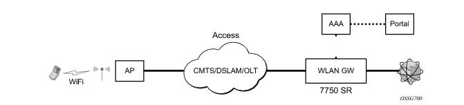
The 7750 SR serves as a WLAN Gateway (WLAN-GW) providing Layer 3 termination and ESM for these subscribers. The connectivity from WLAN AP or AC can be over any existing access technology (DSL, PON, Fiber, DOCSIS, etc.), with Ethernet based connectivity from the access-node (DSLAM, OLT, Eth MTU, Layer 2 CMTS) to the WLAN-GW. WLAN-GW functions could be on a standalone 7750 as shown in Figure 141 or could be an add-on functionality on existing 7750 based BNG as shown in 
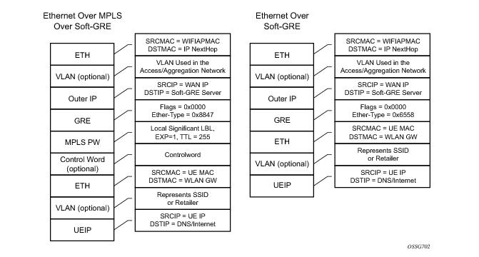
Figure 142. WLAN connectivity to the WLAN-GW could be over a Layer 2 aggregation or an Layer 3 aggregation network (typical when WLAN-GW is upstream of an existing BNG or CMTS). In case of Layer 2 aggregation the connectivity to the WLAN-GW could be tagged or untagged Ethernet. In case of Layer 3 aggregation, supported connectivity option is Ethernet over GRE (or Eth-over-MPLS over GRE) tunnel originating from the AP/AC, and terminating on the WLAN-GW. The WLAN AP acts as a bridge, switching Ethernet frames into a GRE tunnel terminating on an MS-ISA in the WLAN-GW.
Figure 141: Standalone WLAN-GW
Figure 142: WLAN-GW Functions on Existing BNG
AP Connectivity to the WLAN-GW could be direct Ethernet (tagged or untagged) or could be Ethernet over GRE. With the bridged AP using GRE tunnels, the WLAN-GW solution elements are discussed in the following sections.
Layer 2 over Soft-GRE Tunnels
Soft-GRE refers to stateless GRE tunneling, whereby the AP forwards GRE encapsulated traffic to the WLAN-GW, and the GW reflects back the encapsulation in the downstream traffic towards the AP. WLAN-GW does not require any per-AP end-point IP address configuration. The WLAN-GW learns the encapsulation as part of creating the subscriber state on processing the encapsulated control and data traffic. Following are some of the advantages of soft-GRE:
Soft-GRE tunnel termination is performed on dedicated IOMs with MS-ISAs (referred to as WLAN-GW IOM) Each slot requires two MS-ISAs dedicated for soft-GRE tunnel termination. MS-ISA provides tunnel encapsulation/de-capsulation, bandwidth shaping per tunnel (or per-tunnel per SSID), and anchor point for inter-AP mobility. The ESM function such as per-subscriber anti-spoofing (IP and MAC), filters, hierarchical policing, and lawful intercept are provided on the carrier IOM corresponding to the ISA where the subscriber is anchored.
 
Encapsulation
The GRE encapsulation is based on RFC 1701/2784, Generic Routing Encapsulation (GRE), WLAN-GW will encapsulate according to RFC 1701 with all the flag fields set to 0, and no optional fields present. WLAN-GW is able to receive both encapsulation specified in RFC 1701 and RFC 2784, with all flag fields set to 0, and no optional fields present in the header.
Figure 143: Encapsulation Example
The encapsulation is built as follows:
Soft-GRE tunnel termination is performed on dedicated IOMs with MS-ISAs (referred to as WLAN-GW IOM). Each WLAN-GW IOM requires both MS-ISAs to be plugged in for soft-GRE tunnel termination. MS-ISA provides tunnel encapsulation/de-capsulation and anchor point for inter-AP mobility. The carrier IOMs of the ISA where the tunnel is terminated performs bandwidth shaping per tunnel (or per-tunnel per SSID). ESM function such as per-subscriber anti-spoofing (IP and MAC), filters, hierarchical policing, and lawful intercept are provided on the carrier IOM corresponding to the ISA where the subscriber is anchored.
N:M warm standby redundancy is supported for WLAN-GW IOM slots. Up to 4 WLAN-GW IOMs can be configured per 7750. A maximum 3 WLAN-GW IOMs can be active. One or more WLAN-GW group can be configured with set of WLAN-GW IOMs, and a limit of active IOMs. Incoming soft-GRE tunnel contexts and corresponding subscribers are load-balanced amongst the MS-ISAs on active IOMs. Tunnel load-balancing is based on outer source IP address of the tunnel. Subscriber load-balancing is based on UE’s MAC address in the source MAC of the Ethernet payload in the tunnel. IOM(s) beyond the active limit act as warm standby, and take over the tunnel termination and subscriber management functions from failed WLAN-GW slot.MS-ISAs on WLAN-GW IOMs can also be configured to perform NAT function.
 
config isa wlan-gw-group <group-id> 
   [no] active-iom-limit <number>                                     
   [no] description <description-string>                          
   [no] * iom <slot-number> 
      nat
        [no] radius-accounting-policy <nat-accounting-policy>
        [no] session-limits
          [no] reserved <num-sessions>
          [no] watermarks high <percentage> low <percentage>      
   [no] shutdown
 
An ESM and soft-GRE configuration is required for WLAN-GW functions. Subscriber and group interfaces are configured as part of normal ESM configuration. The group interface is enabled for soft-GRE by configuration. The soft-GRE related configuration includes the following:
 
*B:Dut-C>config>service>vprn>sub-if>grp-if>soft-gre# info detail 
----------------------------------------------
                        authentication
                            no authentication-policy
                            hold-time sec 5 
                        exit
                        no data-triggered-ue-creation
                        dhcp
                            shutdown
                            active-lease-time min 10 
                            initial-lease-time min 10 
                            no l2-aware-ip-address
                            no primary-dns
                            no primary-nbns
                            no secondary-dns
                            no secondary-nbns
                        exit
                        egress
                            no agg-rate-limit
                            no hold-time
                            qos 1
                            no scheduler-policy
                            no shape-multi-client-only
                            no shaping
                        exit
                        gw-address 1.1.1.57
                        no gw-ipv6-address
                        no http-redirect-policy
                        no nat-policy
                        mobility
                            hold-time 5
                            no trigger
                        exit
                        router 70
                        no tcp-mss-adjust
                        track-mobility
                            mac-format "aa:"
                            no radius-proxy-cache
                        exit
                        wlan-gw-group 3
                        vlan-tag-ranges
                            no default-retail-svc-id
                            range start 0 end 100
                                authentication
                                    no authentication-policy
                                    hold-time sec 5 
                                exit
                                no data-triggered-ue-creation
                                dhcp
                                    shutdown
                                    active-lease-time min 10 
                                    initial-lease-time min 10 
                                    no l2-aware-ip-address
                                    no primary-dns
                                    no primary-nbns
                                    no secondary-dns
                                    no secondary-nbns
                                exit
                                no http-redirect-policy
                                no nat-policy
                                retail-svc-id 35
                                track-mobility
                                    mac-format "aa:"
                                    no radius-proxy-cache
                                exit
                            exit
                        exit
                        no shutdown
 
 
Data Path
In the upstream direction, the ingress IOM receiving the GRE tunneled packets from the WIFI AP or AC, load-balances tunnel processing amongst the set of MS-ISAs on the active WLAN-GW IOMs in the WLAN-GW group. The load-balancing is based on a hash of source IP address in the outer IP header. The MS-ISA receiving the GRE encapsulated packets removes the tunnel encapsulation, and internally tunnels (MAC-in-MAC, using BVPLS) the packet to an anchor MS-ISA on the WLAN-GW IOM. All traffic from a given UE is always forwarded to the same anchor MS-ISA based on hashing on UE’s MAC address. The MS-ISA provides a mobility anchor point for the UE. The UE MAC’s association to the GRE tunnel identifier is created or updated. The corresponding IOM provides ESM functions including ESM lookup, ingress ACLs and QoS. DHCP packets are forwarded to the CPM from the anchor IOM.
In the downstream direction, the IP packets are forwarded as normal from the network IOM (based on route lookup yielding subscriber subnet) to the IOM where the ESM host is anchored. ESM processing including per UE hierarchical policing and LI is performed on the anchor IOM. Configured MTU on the group-interface is enforced on the IOM, and if required packets are fragmented. The packets are then forwarded to the appropriate anchor MS-ISA housed by this IOM. Lookup based on UE’s MAC address is performed to get the tunnel identification, and the packets are MAC-in-MAC tunneled to the MS-ISA terminating the GRE tunnel. Aggregate shaping on the tunneled traffic (per tunnel or per retailer) is performed on the carrier IOM housing the tunnel termination MS-ISA. The tunnel termination MS-ISA removes MAC-in-MAC encapsulation, and GRE encapsulates the Layer 2 packet, which exits on the Layer 3 SAP to the carrier IOM. The GRE tunneled packet is forwarded to the right access IOM towards the WIFI AP based on a routing lookup on IP DA in the outer header.
Tunnel Level Egress QoS
Downstream traffic can be subjected to aggregate rate-limit per tunnel or per tunnel and per retailer combination (in case of wholesale). Typically a unique SSID is used per retailer for wholesale on the AP, and is reflected via unique dot1Q tag. In the case of soft-GRE tunnel per AP, the tunnel encapsulation is performed on the tunnel ISA. The downstream traffic on the tunnel IOM is received over B-VPLS from the anchor IOM, and is MAC-in-MAC (802.1ah) encapsulated. I-SID in the packet represents the GRE tunnel or tunnel and retailer combination. SAP-egress QoS policy defining queues (with rates), and FC to queue mapping, can be specified under soft-GRE interface. This policy is applicable to all tunnels (or tunnel and SSID combinations) associated with the soft-GRE interface, and is attached to corresponding I-SIDs on the B-VPLS SAP. Traffic is shaped into these queues based on configured queue rates. An aggregate rate-limit applied across queues on an I-SID (representing tunnel or tunnel and retailer combination) can be configured under soft-GRE interface. The aggregate rate-limit works in conjunction with a port-scheduler. The port-scheduler corresponds to the internal port between tunnel ISA and its carrier IOM, and is specified at the WLAN-GW IOM group level. The rate-limit includes the B-VPLS encapsulation overhead. The configuration is shown in Figure 144. Queues per I-SID also work with virtual-scheduler (with or without a port scheduler). Virtual-scheduling and aggregate-rate enforcement are mutually exclusive. Configuration is shown in Figure 145. Egress SAP QoS policy, aggregate rate-limit, port-scheduler, and virtual-schedulers are described in SROS QoS guide. SAP egress QoS policy associated with soft-GRE interface implicitly creates queues (and scheduler association) on ISIDs as corresponding soft-GRE tunnels are created. General ISID queuing and shaping is defined in SROS services guide.
A configuration knob under soft-GRE interface (egress) controls where the egress shaping is applied, and can specify either tunnel or retailer (tunnel and retailer combination in case of wholesale). Per I-SID shaping resources can be held after the last subscriber on the tunnel is deleted, for a configurable amount of time (hold-time) configured under soft-GRE interface. During ISA or IOM failover the tunnel resources on the IOM kept due to hold-time are reclaimed. ISID shaping can be configured (via knob shape-multi-client) to be applied only when there is more than one UE on the corresponding tunnel (or tunnel and retailer combination). A total of 40,000 shaped tunnels (or shaped tunnel & retailer combinations) are supported per WLAN-GW IOM. Hardware resources for tunnel (ISID) shapers are shared with subscribers. With 3 WLAN-GW IOMs per chassis, a maximum of 98,000 (3 *64K / 2) shaped tunnels and subscribers can be supported per chassis.


The following output depicts per tunnel or per tunnel/SSID egress QoS (with aggregate-rate and port-scheduler).
// Port-scheduler
config>qos# 
      port-scheduler-policy “lo-gre-port-sched”
           max-rate 5000
           level 1 rate 1000 cir-rate 1000
           level 8 rate 500 cir-rate 500 
      exit
exit
 
// Egress queues (per ISID) parented by port-scheduler specified under associated soft-GRE interface
config>qos>
   sap-egress 3 create
       queue 1 create
          rate 300
          port-parent level 1 weight 10 cir-level 1 weight 10
       exit
       queue 2 create 
          rate 100
          port-parent level 8 weight 10 cir-level 8 weight 10
       fc af create
           dot1p 2
           de-markweight 
       exit
       fc be create
          queue 1
          dot1p 0
          de-mark
       exit
       fc ef create
           queue 2
           dot1p 5
           de-mark
       exit
   exit
exit
 
// soft-GRE interface refers to SAP egress QoS policy and aggregate rate-limit for associated ISIDs
config>service>ies>sub-if>grp-if>soft-gre>egress
      agg-rate-limit 2000
      hold-time 300
      qos 3
      shaping per-tunnel
      shape-multi-client
exit                 
// Port-scheduler parenting queues (per ISID)
config>isa>wlan-gw-group# 
      active-iom-limit 1
      tunnel-port-policy " lo-gre-port-sched "
      iom 2
      iom 3
      no shutdown
exit
 
Figure 144: Per Tunnel or Per Tunnel/SSID Egress QoS (with aggregate-rate and port-scheduler)
 
The following output depicts per tunnel or per tunnel/SSID egress QoS (with virtual-scheduler).
// hierarchical virtual scheduler 
config>qos# 
      scheduler-policy “virtual-sched-policy”
           tier1
               scheduler “all-traffic” create 
                    rate 10000 
               exit
           exit
           tier2 
               scheduler “non-voice” create
                   parent all-traffic cir-level 1
                   rate 9000
               exit
               scheduler “voice” create
                  parent all-traffic level 2 cir-level 2
                  rate 3000
               exit
           exit
           
       exit
 
// egress queues (per ISID) parented by virtual scheduler
config>qos>
   sap-egress 3 create
       queue 1 create
          parent “non-voice”
          rate 2000 cir 1000
       exit
       queue 2 create 
          parent “voice” 
          rate 500 cir-rate 500 
       fc be create
          queue 1
          dot1p 0
          de-mark
       exit
       fc ef create
           queue 2
           dot1p 5
           de-mark
       exit
   exit
exit
 
// soft-GRE interface refers to SAP egress QoS policy and hierarchical scheduler for associated ISIDs
config>service>ies>sub-if>grp-if>soft-gre>egress
      hold-time 300
      qos 3
      scheduler-policy “virt-sched-policy”
      shaping per-tunnel
      shape-multi-client
exit
 
Figure 145: Per Tunnel or Per Tunnel/SSID Egress QoS (with virtual-scheduler)
 
Operational Commands
Egress per tunnel (or per tunnel, per SSID) QoS with aggregate rate-limit and port-scheduler.
show router 50 wlan-gw soft-gre-tunnels detail
===============================================================================
Soft GRE tunnels
===============================================================================
Remote IP address           : 201.1.1.2
Local IP address            : 50.1.1.1
ISA group ID                : 1
ISA group member ID         : 1
Time established            : 2012/06/19 20:31:36
Number of UE                : 1
 
Tunnel QoS
----------
Operational state           : active
Number of UE                : 1
Remaining hold time (s)     : N/A
Service Access Points(SAP)
===============================================================================
Service Id         : 2147483650
SAP                : 2/1/lo-gre:1             Encap             : q-tag
Description        : Internal SAP
Admin State        : Up                       Oper State        : Up
Flags              : None
Multi Svc Site     : None
Last Status Change : 06/19/2012 07:13:31
Last Mgmt Change   : 06/19/2012 20:30:24
-------------------------------------------------------------------------------
Encap Group Specifics
-------------------------------------------------------------------------------
Encap Group Name   : _tmnx_SHAPER_GR000       Group Type        : ISID
Qos-per-member     : TRUE
Members            :
1
-------------------------------------------------------------------------------
QOS
-------------------------------------------------------------------------------
E. qos-policy      : 3                        Q Frame-Based Acct: Disabled
E. Sched Policy    :                          E. Agg-limit      : 4000
-------------------------------------------------------------------------------
Encap Group Member 1 Base Statistics
-------------------------------------------------------------------------------
Last Cleared Time     : N/A
 
Forwarding Engine Stats
                        Packets                 Octets
For. InProf           : 0                       0
For. OutProf          : 0                       0
Dro. InProf           : 0                       0
Dro. OutProf          : 0                       0
 
-------------------------------------------------------------------------------
Encap Group Member 1 Queue Statistics
-------------------------------------------------------------------------------
                        Packets                 Octets
Egress Queue 1
For. InProf           : 0                       0
For. OutProf          : 0                       0
Dro. InProf           : 0                       0
Dro. OutProf          : 0                       0
===============================================================================
-------------------------------------------------------------------------------
No. of tunnels: 1
===============================================================================
 
 
show qos scheduler-hierarchy sap 2/1/lo-gre:1 encap-group "_tmnx_SHAPER_GR000" member 1 detail
===============================================================================
Scheduler Hierarchy - Sap 2/1/lo-gre:1
===============================================================================
Egress Scheduler Policy :
-------------------------------------------------------------------------------
Legend :
(*) real-time dynamic value
(w) Wire rates
B   Bytes
-------------------------------------------------------------------------------
Root (Egr)
| slot(2)
|--(Q) : -2147483646->2/1/lo-gre:1->EG(_tmnx_SHAPER_GR000):1->1  (Port 2/1/lo-gre Orphan)
|   |    AdminPIR:10000000   AdminCIR:0
|   |    AvgFrmOv:100.00
|   |    AdminPIR:10000000(w) AdminCIR:0(w)
|   |    CBS:0 B             MBS:12582912 B
|   |    Depth:0 B           HiPrio:1376256 B
|   |    MaxAggRate:4000(w)    CurAggRate:0(w)
|   |
|   |    [Within CIR Level 0 Weight 0]
|   |    Assigned:0(w)       Offered:0(w)
|   |    Consumed:0(w)
|   |
|   |    [Above CIR Level 1 Weight 0]
|   |    Assigned:4000(w)    Offered:0(w)
|   |    Consumed:0(w)
|   |
|   |    TotalConsumed:0
|   |    OperPIR:4000        OperCIR:0
|   |
|   |    PktByteOffset:add 0*
|   |    OnTheWireRates:false
|   |    ATMOnTheWireRates:false
|   |    LastMileOnTheWireRates:false
 
Egress per tunnel (or per tunnel, per SSID) QoS with hierarchical virtual scheduler.
show router 50 wlan-gw soft-gre-tunnels detail
===============================================================================
Soft GRE tunnels
===============================================================================
Remote IP address           : 201.1.1.2
Local IP address            : 50.1.1.1
ISA group ID                : 1
ISA group member ID         : 1
Time established            : 2012/06/19 20:43:03
Number of UE                : 1
 
Tunnel QoS
----------
Operational state           : active
Number of UE                : 1
Remaining hold time (s)     : N/A
Service Access Points(SAP)
===============================================================================
Service Id         : 2147483650
SAP                : 2/1/lo-gre:1             Encap             : q-tag
Description        : Internal SAP
Admin State        : Up                       Oper State        : Up
Flags              : None
Multi Svc Site     : None
Last Status Change : 06/19/2012 07:13:31
Last Mgmt Change   : 06/19/2012 20:30:24
-------------------------------------------------------------------------------
Encap Group Specifics
-------------------------------------------------------------------------------
Encap Group Name   : _tmnx_SHAPER_GR000       Group Type        : ISID
Qos-per-member     : TRUE
Members            :
1
-------------------------------------------------------------------------------
QOS
-------------------------------------------------------------------------------
E. qos-policy      : 3                        Q Frame-Based Acct: Disabled
E. Sched Policy    : virtual_scheduler_policy E. Agg-limit      : -1
-------------------------------------------------------------------------------
Encap Group Member 1 Base Statistics
-------------------------------------------------------------------------------
Last Cleared Time     : N/A
 
Forwarding Engine Stats
                        Packets                 Octets
 
For. InProf           : 2                       752
For. OutProf          : 0                       0
Dro. InProf           : 0                       0
Dro. OutProf          : 0                       0
 
-------------------------------------------------------------------------------
Encap Group Member 1 Queue Statistics
-------------------------------------------------------------------------------
                        Packets                 Octets
 
Egress Queue 1
For. InProf           : 2                       752
For. OutProf          : 0                       0
Dro. InProf           : 0                       0
Dro. OutProf          : 0                       0
===============================================================================
-------------------------------------------------------------------------------
No. of tunnels: 1
===============================================================================
 
 
show qos scheduler-hierarchy sap 2/1/lo-gre:1 encap-group "_tmnx_SHAPER_GR000" member 1 detail
===============================================================================
Scheduler Hierarchy - Sap 2/1/lo-gre:1
===============================================================================
Egress Scheduler Policy :
-------------------------------------------------------------------------------
Legend :
(*) real-time dynamic value
(w) Wire rates
B   Bytes
-------------------------------------------------------------------------------
Root (Egr)
| slot(2)
|--(S) : virtual_scheduler (Port 2/1/lo-gre)
|   |    AdminPIR:4000       AdminCIR:0(sum)
|   |
|   |    AvgFrmOv:105.31(*)
|   |    AdminPIR:4212(w)    AdminCIR:0(w)
|   |
|   |    [Within CIR Level 0 Weight 0]
|   |    Assigned:0(w)       Offered:0(w)
|   |    Consumed:0(w)
|   |
|   |    [Above CIR Level 1 Weight 1]
|   |    Assigned:4212(w)    Offered:0(w)
|   |    Consumed:0(w)
|   |
|   |
|   |    TotalConsumed:0(w)
|   |    OperPIR:3999
|   |
|   |    [As Parent]
|   |    Rate:3999
|   |    ConsumedByChildren:0
|   |
|   |
|   |--(Q) : -2147483646->2/1/lo-gre:1->EG(_tmnx_SHAPER_GR000):1->1
|   |   |    AdminPIR:10000000   AdminCIR:0
|   |   |    AvgFrmOv:105.31(*)
|   |   |    CBS:0 B             MBS:12582912 B
|   |   |    Depth:0 B           HiPrio:1376256 B
|   |   |
|   |   |    [Within CIR Level 0 Weight 1]
|   |   |    Assigned:0          Offered:0
|   |   |    Consumed:0
|   |   |
|   |   |    [Above CIR Level 1 Weight 1]
|   |   |    Assigned:3999       Offered:0
|   |   |    Consumed:0
|   |   |
|   |   |    TotalConsumed:0
|   |   |    OperPIR:4000        OperCIR:0
|   |   |
|   |   |    PktByteOffset:add 0*
|   |   |    OnTheWireRates:false
|   |   |    ATMOnTheWireRates:false
|   |   |    LastMileOnTheWireRates:false


Authentication
The solution supports multiple authentication mechanisms. Type of authentication support depends on the WIFI AP, UE capabilities and customer preference. In case of 802.1x/EAP capable WIFI APs, supporting secure SSIDs via 802.11i/WPA2, various EAP based authentication such as SIM/uSIM based (SIM/AKA/AKA’), TTLS, PEAP, certs, etc., are supported. The solution also supports web-portal based authentication with or without WISPr client on the UE. EAP and portal authentication works independent of the type of connectivity from the AP (tunneled or native IP).
 
EAP-Based Authentication
In this model the WIFI AP supports a RADIUS client, and originates RADIUS messages based on 802.1x/EAP exchange with the UE. It sends EAP payload in RADIUS messages towards the RADIUS server or RADIUS proxy. 7750 WLAN-GW can be configured as a RADIUS proxy for the WIFI APs. The WIFI AP should be configured with the IP address of the RADIUS proxy, and should send authentication and accounting messages non-tunneled, natively routed to the RADIUS proxy. See Figure 146.
The RADIUS proxy function allows 7750 SR to look at the RADIUS authentication and accounting messages and create or update corresponding subscriber state. RADIUS proxy transparently forwards RADIUS messages between AP (authenticator) and the AAA server. The access-request message contains standard RADIUS attributes (including user-name), and the EAP payload. Standard authentication algorithms negotiated with EAP involve multiple round-trips (challenge/response) between AP (and UE) and the AAA server.
Once authentication is complete, AAA server passes back subscriber related configuration parameters as well as the computed session keys (aka pair-wise master key) for 802.11i to the AP. These keys are encrypted using shared secret between AP (authenticator) and the AAA server. 7750 WLAN-GW can optionally cache authentication information of the subscriber from access-request and access-accept messages. The cached information allows local authorization of subsequent DHCP messages from the UEs behind the AP against the cached state on the 7750 RADIUS proxy, and avoids another trip to the RADIUS server.
Figure 146: EAP Authentication Call Flow with WLAN-GW RADIUS Proxy
 
RADIUS Proxy
RADIUS proxy can be configured per service router (base or VPRN). The proxy acts as a server towards the WIFI AP RADIUS clients, and as a client towards RADIUS server(s). Therefore, both client and server parts of the RADIUS proxy need to be configured. The attribute from access-request or response message that serves as the key for the cache is configurable. The key configuration is mandatory for enabling the cache. Commonly the key is the MAC address of the UE, which is available in subsequent DHCP request, and used to locate the cache entry. The UE’s MAC address is typically available in the Calling-station-Id attribute (31) in the RADIUS access-request message from the AP. The proxy can be configured for both authentication and accounting. The radius server policies referred by RADIUS proxy are configured under “aaa” context. If caching is enabled in the RADIUS proxy, the subscriber attributes returned in access-accept are cached. These can include 802.1x credentials/keys, IP address or pool, DNS information, default gateway information, retail-service-id, SLA-profile, filter parameters, charging information, session keys (MS-MPPE-RECV-KEY, MS-MPPE-SEND-KEY) etc. If subsequent DHCP DISCOVER is not received within the configured timeout, the cache entry is removed.
The following output displays a RADIUS proxy configuration.
config>service>ies>
config>service>vprn>
     description "Default Description For VPRN ID 50"
        interface "listening_radius_server" create
          address 9.9.9.9/32
          loopback
        exit
 
     radius-proxy
         server "radius_proxy" purpose accounting authentication create
             cache
                 key packet-type request attribute-type 31
                 timeout min 5
                 track-accounting stop interim-update accounting-on accounting-off
                 no shutdown
             exit
             default-accounting-server-policy "radius_acct_server_policy"
             default-authentication-server-policy "radius_Auth_server_policy"
             interface "listening_radius_server"
             load-balance-key attribute-type 102 vendor 5
             secret "AQepKzndDzjRI5g38L3LbbN3E8qualtn" hash2
             send-accounting-response
             no shutdown
         exit
 
 
RADIUS Proxy — Server Load-Balancing
RADIUS proxy can be configured for load-balancing to multiple authentication and accounting servers. Load-balancing can be “round-robin” or “hash” based, and is configured via access-algorithm under RADIUS policy. With round-robin the first RADIUS request is sent to the first server, the second request to the second server and so on. With hash, it is possible to load-balance subscribers across a set of servers. Based on the configured hash key, configured in the RADIUS proxy, it can be ensured that all RADIUS messages for a single subscriber are sent to the same server. The hash key can include any specified standard or vendor-specific RADIUS attribute. An example is calling-station-id which contains subscriber’s MAC address).
If the hash lookup causes the request to be sent to a server that is currently known to be unresponsive, a second hash lookup is performed that only takes the servers into account that are not known to be unresponsive. This is done to maximize the likelihood that all requests will end on the same server. If all configured servers are known to be unresponsive, the RADIUS proxy will fall back to the round-robin algorithm with the starting point determined by the first hash lookup to maximize the chance of getting any response to the request.
The following output displays a RADIUS server and policy configuration for servers referred from the RADIUS proxy.
 
config>service>vprn
   radius-server
      server "radius_server" address 100.100.100.2 secret "9OkclHYDDbo9eHrzFmuxiaO/LAft3Pw" 
                             hash2 port 1812 create
      exit
   exit
 
config>aaa
   radius-server-policy "radius_server_policy" create
      servers
         router 50
         access-algorithm hash-based
         source-address 10.1.1.1
         timeout min 1
         hold-down-time 2
         server 1 name "radius_server"
      exit
 
RADIUS Proxy — Cache Lookup
Local-user-database can be programmed to associate a host match with the RADIUS proxy cache instance. The host-match criterion is configurable, based on a subscriber attribute from the DHCP request.
The following output displays a RADIUS proxy cache lookup configuration.
 
config>subscriber-mgmt
   local-user-db "radius_ludb" create
       dhcp
           match-list service-id 
           host "default" create
           auth-policy "auth_policy_1"
           match-radius-proxy-cache
              fail-action continue
              match mac
              server router 50 name "radius_proxy"
           exit
              no shutdown
        exit
        no shutdown
    exit     
exit
 
If caching is enabled in the RADIUS proxy, then the actions on receiving DHCP message for the authenticated client includes the following:
 
RADIUS Proxy — Accounting
An ESM accounting-start is generated once the ESM host is created on successful authorization of DHCP against cached authentication state, and IP@ allocation is complete. The accounting-start contains information from locally cached 802.1x/EAP authentication such as calling-station-id, called-station-id, NAS-port-id, Subscriber-profile, SLA-profile, NAT port range for subscriber-aware NAT etc.
If RADIUS proxy is configured as an accounting proxy in addition to authentication proxy, then the RADIUS proxy transparently forwards the accounting messages to the authentication server(s) referred from the RADIUS proxy, and can also load-balance. If caching is enabled, then the proxy can be configured to also track and locally act on the accounting messages, while still transparently forwarding these messages. The possible actions if accounting messages are tracked include the following:
 
Portal Authentication
For SSIDs without 802.11i/WPA2-based key exchange and encryption, it is common to authenticate the user by directing user’s HTTP traffic to a portal, where the user is prompted for its credentials, which are verified against a subscriber database. The backend can optionally remember the MAC@ and subscriber credentials for a set period of time such that subsequent logins of the user do not require portal redirection. Some UEs support a client application (aka WISPr client), which automatically posts subscriber credentials on redirect, and parse HTTP success or failure response from the portal sever.
7750 WLAN-GW uses existing http-redirect action in IP filter to trigger redirect port-80 traffic. In case of open SSID, on receiving DHCP DISCOVER, MAC based authentication is performed with the RADIUS server as per configured authentication policy. The SLA-profile returned from RADIUS server in authentication-accept (or the default SLA-profile) contains the filter with http-redirect. Redirect via HTTP 302 message to the UE is triggered from the CPM. Once the user posts its credentials, RADIUS server generates a CoA-request message removing the http-redirect by specifying an SLA-profile without redirect action. If the portal authentication fails, the RADIUS server generates a disconnect-request message to remove the ESM host. In case of soft-GRE tunnel from the AP, the DHCP messages and data are both tunneled to the WLAN-GW. See Figure 147.
Figure 147: Portal Authentication for Open SSIDs
The following output displays a portal authentication for open SSIDs configuration example.
config>subscriber-mgmt
      sla-profile "portal-redirect" create
          ingress
             ip-filter 10
          exit
      exit
   exit
 
system>config>filter   
   ip-filter 10 create
       entry 1 create
            match protocol udp
                dst-port range 67 68 
            exit 
            action forward
       exit
       entry 2 create
           match protocol tcp
               dst-port eq 80 
           exit 
           action http-redirect "http://www.google.ca"
       exit
   exit
exit
                    
Address Assignment
The address to the UEs can be assigned via local DHCP server from locally defined pools, or from RADIUS server via local DHCP proxy, or from an external DHCP server. Subscriber-interface and group-interface are configured as part of normal ESM configuration. In case of soft-GRE, the group-interface is soft-GRE enabled. Subnets on the subscriber interface are used for the pools from which the DHCP local server assigns addresses to UEs.
The following output displays an address assignment configuration example.
config>service>vprn       
    dhcp  
       local-dhcp-server "dhcp" create    #### create local DHCP server
           pool “1” create                #### define Pool
               options
                   dns-server 8.8.8.8 8.8.4.4
                   lease-time min 5
               exit
               subnet 128.203.254.180/30 create   
                  options
                     subnet-mask 255.255.0.0
                     default-router 128.203.254.181
                  exit
                  address-range 128.203.254.182 128.203.254.183 
               exit
             exit
         exit
     exit
             
    interface "DHCP-lb" create          #### loopback interface with DHCP server           
        address 10.1.1.1/32
        local-dhcp-server "dhcp"
        loopback
    exit 
               
    subscriber-interface "sub-int" create          #### subscriber interface
         address 128.203.254.181/30                #### Subnets out of which UE  
         address 10.10.0.1/16                      ######  addresses are allocated.  
         group-interface "group-int" softgre create
             sap-parameters
                 sub-sla-mgmt
                   def-sla-profile "sla_def"
                   def-sub-profile "sub_def"
                   sub-ident-policy "sub_ident"
                 exit
              exit
         exit
         dhcp
             proxy-server
                 emulated-server 10.10.0.1   #### proxy to get IP address from AAA
                 lease-time min 5            #### or from DHCP server. Can provide   
                 no shutdown                 #### split lease (shorter lease towards client, 
              exit                           #### and longer lease towards AAA or DHCP server.
              no option                       
              server 10.1.1.1                #### DHCP local server           
                  trusted
                  lease-populate 32000
                  gi-address 128.203.254.181
                  user-db "radius_ludb"      #### LUDB for proxy cache co-relation      
                  no shutdown
               exit
          exit


WIFI Mobility Anchor
7750 WLAN-GW supports seamless handling for UE mobility, when a UE moves from one AP to another, where the new AP is broadcasting the same SSID, and is anchored on the same WLAN-GW. In case of open SSID, when the UE re-associates with the same SSID on the new AP and already has an IP@ from association with previous AP, the UE can continue to send and receive data. The WLAN-GW learns the association of the UE’s MAC address to the GRE tunnel corresponding to the new AP, and updates its state on the MS-ISA as well as on the CPM. The UE continues to be anchored on the same anchor MS-ISA, thereby avoiding any disruption in ESM functions (SLA enforcement and accounting). State update based on data learning results in fast convergence after mobility and minimal packet loss. The data-triggered mobility can be turned on via configuration. Mobility trigger can be configured to be restricted to special Ethernet IAPP frame (originated by the AP with the source MAC of UE).
For 802.1x/EAP based SSIDs, by default the AP requires re-authentication to learn the new session keys (PMK). 7750-SR as WLAN-GW RADIUS proxy infers mobility from the re-authentication, and updates the ESM host to point to the new AP. The new AP’s IP address is derived from the RADIUS attribute NAS-IP-address.The re-authentication also provides the new session keys to the AP in access-accept RADIUS response. In case the WIFI AP or ACs are capable of PMK key caching or standard 802.11r (or OKC, the opportunistic key caching pre-802.11r), the re-authentication on re-association can be avoided. In this case the UE can continue to send data, and the WLAN-GW can provide fast data-triggered mobility as defined in context of open SSIDs.
The following output provides a mobility anchor configuration example.
 
config>service>ies>
config>service>vprn>
subscriber-interface <if-name> 
group-interface <if-name> softgre
    soft-gre
      [no] router (base | <vprn-id>) # tunnel service context
      [no] wlan-gw-group <group-id>			
      ....snip
       mobility
         [no] trigger {data | iapp}
         [no] hold-time <seconds> // [0..255 secs]
       exit
     exit
exit


Wholesale
With EAP the AAA server can look at the realm from the user credential (IMSI) in authentication request and appropriately provide the service context in retail-service-id, for the ESM host corresponding to the UE.
For open SSID, the decision can be made by the AAA server based on the SSID. The SSID is encapsulated in circuit-id sub-option of option-82. The recommended format for the circuit-id is a string composed of multiple parts (separated by a delimiter) as shown below.
AP-MAC;SSID-STRING;SSID-TYPE
Delimiter is the character ‘;’, and MUST not be allowed in configured SSIDs. AP-MAC sub-string MUST contain the MAC address of the AP in the format “xx:xx:xx:xx:xx:xx”
SSID-TYPE is “o” for open, and “s” for secure.
For example, if AP-MAC is “00:10:A4:23:19:C0”, SSID is “SP1-wifi”, and SSID-type is secure, then the value of circuit-id would be the string “00:10:A4:23:19:C0;SP1-wifi;s”.
The circuit-id is passed to the AAA server in initial MAC based authentication on DHCP DISCOVER. The retail-service-id can be returned in access-accept. This assumes the AP broadcasts unique SSID per retail provider, and inserts it in Option82 as a DHCP relay-agent. As an alternative to SSID in option-82, the AP can insert a unique dot1Q tag per retail provider, before tunneling the Ethernet frame, using single GRE tunnel per AP to the WLAN-GW. 7750 supports configuring a map of .dot1Q tags to retail-service-id. Therefore, the determination of the retail provider for the subscriber can be made in the data plane when DHCP is received, and the subscriber state can be created and processed in the right service context.
The following output displays a wholesale configuration example.
config>service>ies>
config>service>vprn>
subscriber-interface <if-name> 
group-interface <if-name> softgre
    soft-gre
	[no] router (base | <vprn-id>) # tunnel service context
	[no] wlan-gw-group <group-id>			
	....snip
	vlan-tag-ranges # Precedence for retail-service-id: 
                                 # RADIUS, vlan-retail-service-map, default-retail-svc                                                     
	  [no] vlan start <start-tag> end <end-tag> retail-svc-id <svc-id>
	  [no] default-retail-svc-id
	exit
	exit
exit


CGN on WLAN-GW
Both LSN and L2-aware NAT for WIFI subscribers over soft-GRE tunnels is supported. NAT on WLAN-GW is only supported for locally terminated subscribers and not for GTP tunneled subscribers. NAT can be performed on the same set of ISAs that are used for WLAN-GW functions, by referring to the WLAN-GW ISA group from NAT configuration. Alternatively, dedicated set of ISAs can be used for NAT function by creating and referencing a separate NAT-group. Configuration related to LSN and L2-aware NAT is provided in SROS MS-ISA guide.
 
Lawful Intercept on WLAN-GW
Mirroring traffic for WIFI subscribers to a mediation device, when the subscriber is under legal intercept is supported. The mirroring function is performed on the anchor IOM where the subscriber is anchored. Both Ether and IP-only mirror is supported. With Ether mirror, VLAN tags which are part of internal SAP between ISA and IOM, are included in the mirrored Ethernet frame of the subscriber. IP-only mirror includes the IP header and the payload. Conventional IP-only mirror service can be used with direct p2p or MPLS (for remote mirroring) connection to the mediation device. In addition, routable-encapsulation added in 10R1 is also supported. Both IP/UDP encapsulation with optional shim-header for subscriber correlation on the mediation device, and IP/GRE encapsulation is supported with routable-encapsulation of mirrored data. LI can be triggered via CLI, SNMPv3 or RADIUS, as supported with ESM. RADIUS triggered LI can be via LI related VSAs in access-accept or in CoA. The CoA is keyed on accounting-session-id. LI is supported for both local and GTP tunnelled subscribers.
Existing LI support with ESM is described in the SROS OAM and diagnostics guide.
 
WIFI Offload – 3G/4G Interworking
This feature adds support for WIFI to 3G/4G interworking on WLAN-GW based on setting up per-UE GTP tunnel from WLAN-GW to the mobile packet core. The feature involves setting up per-UE GTP tunnel from the WLAN-GW to the GGSN or PGW based on authenticating the UE. Access to only a single APN (default WLAN APN) per UE is supported. This default WLAN APN for the UE is obtained in authentication response from the AAA server. A single primary PDP context per UE is supported on the Gn interface (3GPP TS 29.060 Release 8) from WLAN-GW to the GGSN. Single default-bearer per UE is supported on S2b interface (3GPP TS 29.274 Release 10), and S2a interface (work-in-progress for SAMOG Release 11) from WLAN-GW to the PGW. The GTP tunnel setup is triggered via DHCP from the UE after it is successfully authenticated. The IP@ for the UE is obtained via GTP from the GGSN or PGW and returned to the UE in DHCP. The bridged WIFI AP connectivity with the WLAN-GW can be soft-GRE based (L2oGRE or L2VPNoGRE) or can be a native L2 (VLAN). A maximum of 128,000 PDP-contexts or bearers are supported per WLAN-GW. GTP-U encapsulation requires IOM3.
 
Signaling Call Flow
The decision to setup a GTP tunnel for a subscriber or locally breakout subscriber’s traffic is AAA based, and received in authentication response. If the traffic is to be tunneled to the PGW or GGSN, the signaling interface or PGW/GGSN interface would be provided via AAA. Absence of these attributes in the authentication response implicitly signifies local-breakout.
 
GTP Setup with EAP Authentication
Once the EAP authentication completes as described in the section on authentication, the RADIUS proxy caches the authentication response, including any attributes related to GTP signaling. Subsequently DHCP is initiated from the UE. On receiving DHCP DISCOVER, the RADIUS proxy cache is matched to get the AAA parameters related to the UE from the original authentication response. If PGW/GGSN (mobile gateway) IP address is not present in cached authentication, DNS resolution as described in section 1.2 is initiated for the WLAN APN obtained from AAA (in the cache) or for locally configured APN in the service associated with the UE. The DNS resolution provides a set of IP addresses for the mobile gateways. The GTP tunnel setup is attempted to the selected mobile gateway. The IP address provided by PGW/GGSN in the GTP response is returned in DHCP offer to the UE. The WLAN-GW acts as a DHCP to GTP proxy. The WLAN-GW is the default-GW for the UE. Any packets from the UE are then GTP tunneled to the mobile gateway. If the UE requests an IP address (for which it may have an existing lease on one of its interface) via DHCP option 50 in the DHCP request, then WLAN-GW sets the “handover bit” in the GTP session create message, and indicates the requested address in the PDN Address Allocation (PAA) field. This allows the PGW to look for existing session corresponding to the signaled IMSI and APN (with potentially different RAT-Type) and return its existing IP address in session create response. The old session and bearer is deleted by the PGW. The signaling of “handover bit” is supported with S2a and S2b (release 10 and beyond). The IP address cannot be preserved over the Gn interface. The call flow in Figure 152 shows basic GTP setup (with S2a), the output provided on show IP address preservation across inter-access (WIFI <-> 4G) moves.
DHCP release or lease timeout on WLAN-GW will result in deletion of the GTP tunnel corresponding to the UE. The session or PDP context deactivation from PGW/GGSN will also result in removal of the GTP state for the UE and the corresponding ESM host on WLAN-GW. In this SR-OS release, only default bearer (or primary PDP context) for single default APN is handled over WIFI. GTP path-management messages (echo request and reply) are supported. Mandatory IEs are supported in GTP signaling. Hard coded default values are signaled for QoS and charging related IEs. For GTPv2, the bearer is signaled as non-GBR bearer with QCI value of 8, and MBR/GBR values of 0. APN-AMBR default values signaled are 20Mbps/10Mbps downstream/upstream. For GTPv1, reliability and priority classes default to “best-effort”, allocation/retention priority defaults to 1, and the default peak-rate corresponds to class 9 (bit-wise 1001) which is slightly over 2Mbps. Charging characteristics IE which contains a 16 bit flag defaults to 0. In the future, RADIUS returned values or locally configurable values will be signaled in QoS and charging IEs.
The IP address is returned in the create PDP context response or Create session response. The DNS server addresses for the UE are retuned in IP control protocol (IPCP) option in a PCO IE in the response. The default gateway address provided to the UE in DHCP is auto-generated algorithmically on the WLAN-GW from the IP address returned by the PGW/GGSN for the UE. The WIFI AP is required to provide a split-horizon function, where there is no local switching on the AP, and all communication to/from any AP is via WLAN-GW. The WLAN-GW implements proxy-ARP and forwards all received traffic from the UE into the GTP tunnel. In the future, the default-GW address to be returned to the UE could be obtained in a PCO from the PGW/GGSN. The GTP-U processing of data packets is done in the IOM.
 
APN Resolution
The default WLAN APN is either configured via CLI or obtained from RADIUS in authentication response. The APN FQDN is constructed and resolved in DNS to obtain a set of GGSN/PGW IP addresses. The GTP sessions for UEs are load-balanced across the set of these gateways in a round-robin fashion. The APN FQDN generated for DNS resolution is composed of the Network-ID (NI) portion and the Operator-ID (OI) portion (MCC and MNC) as per 3GPP TS 29.303 and is formatted as APN-NI.apn.epc.mnc<MNC>.mcc<MCC>.3gppnetwork.org. Only basic DNS procedure and A-records from DNS server are supported in this release. S-NAPTR procedure is not yet supported and will be added in a follow-on release. The NI portion or both NI and OI portions of the APN can be locally configured or supplied via RADIUS in a VSA (Alc-Wlan-APN-Name). By default the Operator-ID (OI) portion of the APN is learnt from the IMSI. If the RADIUS returns both the NI and OI portions in the APN attribute, then it is used as is for the FQDN construction. A DNS resolution is limited to a maximum of 20 IP addresses in this
Configuration Objects
The Mobile gateway (PGW or GGSN) IP address can be obtained via DNS resolution of the AP or provided by AAA server in authentication response. Profiles with signaling related configuration per mobile gateway can be created locally on the WLAN-GW. A map of these profiles (mgw-profiles) keyed on the IP@ of the mobile gateway is configurable per router. The serving network (<MCC> & <MNC>) that the WLAN-GW belongs to is configurable per system. The configurable signaling information per mobile gateway includes the type of interface between WLAN-GW and the mobile gateway (Gn, S2a, or S2b), path management parameters, and retransmission parameters for signaling messages. The type of signaling interface can also be explicitly overridden via RADIUS in authentication response. DNS servers and source IP address to be used for DNS resolutions can be configured in the service the APN corresponds to.
GTP related configuration on WLAN-GW
config>subscriber-mgmt>wlan-gw 
   serving-network mcc “123” mnc “45” 
   mgw-profile “pgw-west-mno1” [create]                         
      description “mgw profile for MNO north-east PGW”
      interface-type s2b
      ip-ttl 255
      keep-alive interval 60 retry-count 3 timeout 10
      message-retransmit timeout 30 retry-count 3
    exit
 
 
config>router
config>service>vprn
    apn “internet.mno1.apn”
    mgw-map
        address 33.1.1.1/32 “pgw-west-mno1”
        address 34.1.1.1/32 “ggsn-east-mno1”
    exit
 
config>service>vprn>dns
     primary-dns 130.1.1.1
     secondary-dns 131.1.1.1
     tertiary-dns 132.1.1.1
     ipv4-source-address 170.1.1.1
 exit
 
Figure 148: GTP Signaling to PGW or GGSN Based on AAA Decision
Figure 149: LTE to WIFI Mobility with IP Address Preservation
Figure 150: WIFI to LTE Mobility with IP Address Preservation
 
RADIUS Support
Table 20describes 3GPP attributes and ALU specific attributes related to GTP signaling are supported.
 
 
QoS Support with GTP
WLAN-GW provides appropriate traffic treatment and (re)marking based on DSCP bits in the outer and/or inner header in GTP packet. In the downstream (PGW/GGSN to WLAN-GW) direction, the DSCP bits from the inner and/or outer header in GTP packet can be mapped to a forwarding class which can be preserved through the chassis as the packet passes to the egress IOM. In case of soft-GRE, as the packet passes through the ISA(s), the FC is carried through (based on static mapping of FC to dot1P bits in internal encapsulation using VLAN tags through the ISAs). The egress IOM (which forwards the GRE tunneled packet towards the AP) can classify on FC to set the DSCP bits in the outer GRE header based on configuration.
In the upstream direction, the DSCP bits from the soft-GRE can be mapped to the DSCP bits in the outer header in GTP encapsulated packet.
 
Operational Commands
These commands show state related to mobile gateways and GTP sessions.
show router wlan-gw 
           mobile-gateway – Display mobile gateway information
           mgw-map – Display the mobile gateway map
           mgw-address-cache – Display the mobile gateway’s DNS lookup address cache.
 
show router wlan-gw mgw-address-cache [apn <apn-string>]
                       <apn-string>         : [80 chars max]
 
show router wlan-gw mobile-gateway
                [mgw-profile <profile-name>] [local-address <ip-address>] [control <protocol>]
                remote-address <ip-address> [udp-port <port>]
                remote-address <ip-address> [udp-port <port>] statistics
 
<profile-name>       : [32 chars max]
 	<ip-address>            : ipv4-address   - a.b.c.d
               <ipv6-address   - x:x:x:x:x:x:x:x   (eight 16-bit pieces)
                                             x:x:x:x:x:x:d.d.d.d
                                             x - [0..FFFF]H
                                            d - [0..255]D
               <protocol>          : gtpv1-c|gtpv2-c
               <port>                 : [1..65535]
 
show router wlan-gw mobile-gateway
===============================================================================
Mobile gateways
===============================================================================
Remote address              : 5.20.1.2
UDP port                          : 2123
-------------------------------------------------------------------------------
State                              : up
Local address               : 5.20.1.3
Profile                           : default
Control protocol         : gtpv1-c
Restart count              : 3
Time                             : 2012/06/28 08:07:11
 
 
show router 300 wlan-gw mgw-address-cache
===============================================================================
Mobile Gateway address cache
===============================================================================
APN    : full.dotted.apn.apn.epc.mnc010.mcc206.3gppnetwork.org
-------------------------------------------------------------------------------
Mobile Gateway address      : 5.20.1.2
Time left (s)                             : 3587
-------------------------------------------------------------------------------
No. of cache entries: 1
No. of Mobile gateways: 1
===============================================================================


show subscriber-mgmt wlan-gw
      gtp-session     - Display GTP session information
      gtp-statistics  - Display GTP statistics
      mgw-profile     - Display Mobile Gateway profile information
      
show subscriber-mgmt wlan-gw gtp-session
              imsi <imsi> apn <apn-string>
              [mgw-address <ip-address>] [mgw-router <router-instance>] [remote-control-teid <teid>] [local-
        control-teid <teid>] [detail]
              imsi <imsi>
                   <imsi>               : [a string of digits between 9 and 15 long]
                  <apn-string>         : [80 chars max]
                  <ip-address>         : ipv4-address   - a.b.c.d
                   <ipv6-address>      : x:x:x:x:x:x:x:x   (eight 16-bit pieces)
                                                       x:x:x:x:x:x:d.d.d.d
                                                       x - [0..FFFF]H
                                                       d - [0..255]D
                     <router-instance>    : <router-name>|<service-id>
                                                     router-name    - "Base"
                                                     service-id     - [1..2147483647]
                     <teid>               : [1..4294967295]


show subscriber-mgmt wlan-gw gtp-statistics
show subscriber-mgmt wlan-gw mgw-profile
            <profile-name>
            <profile-name> associations
            mgw-profile
                        <profile-name>       : [32 chars max]
 
 
show subscriber-mgmt wlan-gw gtp-session detail
===============================================================================
GTP sessions
===============================================================================
IMSI                        : 206100000000041
APN                         : full.dotted.apn.mnc010.mcc206.gprs
-------------------------------------------------------------------------------
Mobile Gateway router       : "Base"
Mobile Gateway address      : 5.20.1.2
Remote control TEID         : 1119232
Local control TEID          : 4293918976
Bearer 5 rem TEID           : 1074861061
Bearer 5 loc TEID           : 4293919013
-------------------------------------------------------------------------------
No. of GTP sessions: 1
===============================================================================
 
 
show subscriber-mgmt wlan-gw mgw-profile "default"
===============================================================================
WLAN Mobile Gateway profile "default"
===============================================================================
Description                          : (Not Specified)
Retransmit timeout (s)         : 5
Retransmit retries                : 3
Keepalive interval (s)          : 60
Keepalive retries                 : 4
Keepalive retry timeout (s) : 5
Time to live                         : 255
Interface type                      : s2a
Last management change   : 06/28/2012 06:05:30
===============================================================================
 
 
show subscriber-mgmt wlan-gw gtp-statistics
=============================================================================
GTP statistics
=============================================================================
tx echo requests                                        : 1
tx echo responses                                       : 0
tx errors                                               : 0
rx echo requests                                        : 0
rx echo responses                                       : 1
rx errors                                               : 0
rx version not supported                                : 0
rx zero TEID responses                                  : 0
path faults                                             : 0
path restarts                                           : 0
tx invalid msgs                                         : 0
tx create PDP context requests                          : 0
tx create PDP context responses                         : 0
tx delete PDP context requests                          : 0
tx delete PDP context responses                         : 0
tx create session requests                              : 1
tx create session responses                             : 0
tx delete session requests                              : 0
tx delete session responses                             : 0
tx delete bearer requests                               : 0
tx delete bearer responses                              : 0
tx error indication count                               : 0
rx invalid msgs                                         : 0
rx create PDP context requests                          : 0
rx create PDP context responses                         : 0
rx delete PDP context requests                          : 0
rx delete PDP context responses                         : 0
rx create session requests                              : 0
rx create session responses                             : 1
rx delete session requests                              : 0
rx delete session responses                             : 0
rx delete bearer requests                               : 0
rx delete bearer responses                              : 0
rx error indication count                               : 0
rx invalid pkt length                                   : 0
rx unknown pkts                                         : 0
rx missing IE pkts                                      : 0
rx bad IP header pkts                                   : 0
rx bad UDP header pkts                                  : 0
============================================================================


Migrant User Support
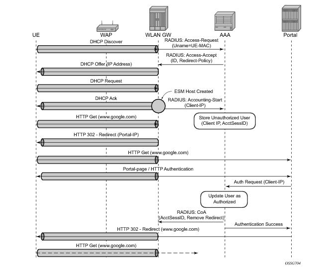
“Migrant users” are UEs that connect to an SSID, but move out of the range of the access-point before initiating or completing authentication. For open-SSIDs, a migrant user may stay in the range of the access-point just enough to get a DHCP lease from the WLAN-GW. In real WIFI deployments with portal authentication, it has been observed that a large percentage of users are migrant, such as get a DHCP lease but do not initiate or complete authentication. Prior to this feature, an ESM host is created when DHCP completes. This results in consumption of resources on both CPM and IOM, limiting the ESM scale and performance for fully authenticated active users. This feature adds support to only create an ESM host after a user has been fully authenticated, either via web portal or with a AAA server based on completing EAP exchange. In addition, with this feature L2-aware NAPT is enabled on the ISA, such that each UE gets the same shared configured inside IP@ from the ISA via DHCP. Until a user is authenticated, forwarding of user traffic is constrained (via policy) to only access DNS and portal servers. Each user is allocated a small number of configured NAT outside ports to minimize public IP address consumption for unauthenticated users. Once the user is successfully authenticated, as indicated via a RADIUS COA on successful portal authentication, an ESM host is created, and the L2-aware NAT is applied via a normal per-subscriber NAT policy. The inside IP address of the user does not change. The outside IP pool used is as per the NAT policy, and the L2-aware NAT could be 1:1 or NAPT with larger number of outside ports than in the un-authenticated phase. If a user is already pre-authenticated (for example, if RADIUS server remembers the MAC@ of the UE from previous successful portal authentication), then the initial access-accept from RADIUS will trigger the creation of the ESM host.
Migrant user support is only applicable to EAP based closed SSIDs when RADIUS-proxy is not enabled on WLAN-GW. This is described in Migrant User Support with EAP Authentication.
 
Migrant User Support with Portal-Authentication
 
DHCP
Based on DHCP and L2 NAT configuration on the ISA, IP address is assigned to the user via DHCP. A different DHCP lease-time can be configured for an un-authenticated user and an authenticated user for which an ESM host has been created. DHCP return options, for example, DNS and NBNS server addresses can be configured. This configuration can be per soft-GRE group interface or per VLAN range (where a VLAN tag corresponds to an SSID). Once the DHCP ACK is sent back to the UE from the ISA, the UE will be created on the ISA in “migrant (or unauthenticated) state”. ARP requests coming from the UE in migrant state will be responded to from the ISA. The authentication to RADIUS is triggered on receiving first L3 data-packet as opposed to on DHCP DISCOVER.
 
Authentication and Forwarding
The authentication is initiated from RADIUS client on the ISA anchoring the user, based on an isa-radius-policy (configured under aaa) and specified on the soft-GRE group-interface. The initial access-accept from RADIUS can indicate if a user needs to be portal authenticated or is a pre-authenticated user. The indication is based on inclusion of a “redirect policy” applicable to the user, in a VSA (Alc-Wlan-Portal-Redirect, type = string). The access-accept can also include a redirect URL VSA (Alc-Wlan-Portal-Url, type = string) for the user. An empty Alc-Wlan-Portal_redirect VSA forces the use of locally configured redirect policy. Also, if neither of the above two VSAs are included, then this indicates a “pre-authenticated user”, and an ESM host is created for the subscriber with subscriber-profile and other subscriber configuration from access-accept, and from here normal ESM based forwarding occurs for the subscriber.
However, if a user needs portal authentication (as indicated in access-accept), then while the user is pending authentication, forwarding is restricted to DNS and portal servers via the redirect policy. The redirect policy is an IP ACL that restricts forwarding based on IP destination, destination port, and protocol, and also specifies http-redirect for http traffic that does not match any of the forwarding rules. The URL for re-direct is configured in the redirect policy or can be provided in authentication-accept. A Maximum of 16 redirect policies can be created in the system, with a maximum of 64 forward rules across all redirect policies. During this “authentication pending” phase all forwarded traffic is subjected to L2-aware NAT on the ISA. The NAT policy to use for these users can be configured on the soft-GRE interface or per VLAN range under the soft-GRE interface. After an access-accept has been received from RADIUS for such a user, the next http packet triggers a redirect function from the ISA, and an http 302 is sent to the client. The redirect can be configured to append original-URL, subscriber’s MAC address and IP address to the redirect URL sent back in http 302. The client presents its credentials to the portal and once it is successfully authenticated, a COA is generated from the RADIUS server (triggered by the portal). The COA message triggers creation of an ESM host with the subscriber configuration contained in the COA such as subscriber-profile, SLA-profile, NAT-profile and application-profile. From this point normal ESM based forwarding occurs for the subscriber.
The configuration related to migrant users is shown on .
 
Migrant User Support with EAP Authentication
Migrant user support can only be used for closed SSIDs when there is no RADIUS-proxy configured on WLAN-GW. If no RADIUS proxy is configured, then initial RADIUS request carrying EAP from the AP is normally forwarded to a RADIUS server. The RADIUS exchange is between AP and the AAA server, and no information from EAP authentication is cached on the WLAN-GW. The subsequent DHCP DISCOVER after successful EAP authentication is received on the ISA. However, for subscriber that needs to be GTP tunneled to PGW/GGSN, the DHCP is forwarded to the CPM, where it triggers a RADIUS authorization. RADIUS correlates the MAC address with calling-station-id from EAP authentication for the user. GTP tunnel initiation, and ESM host creation then follows after receiving an access-accept. However, for a “local-breakout” subscriber DHCP and L2-aware NAT is handled on the ISA (as in the case for migrant users with portal based authentication). Shared inside IP address can be handed out to each subscriber. The first L3 packet triggers MAC address based RADIUS authorization from the ISA. RADIUS server can correlate the EAP authentication with the MAC address of the user and send an access-accept. This triggers ESM host creation as normal.
For closed SSIDs with EAP authentication, if a RADIUS proxy function is configured on WLAN-GW, then the initial EAP authentication from the AP is processed by the RADIUS-proxy on the CPM, and is forwarded to the RADIUS server based on configured authentication policy. Based on authentication response, ESM host creation with local DHCP address assignment or GTP tunnel initiation proceeds as usual.
 
Data Triggered Subscriber Creation
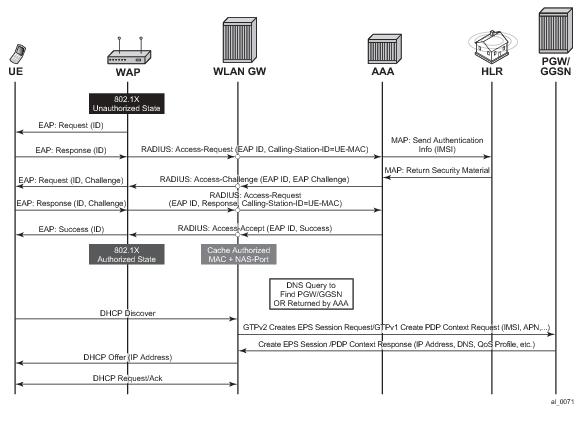
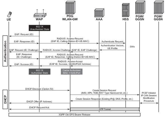
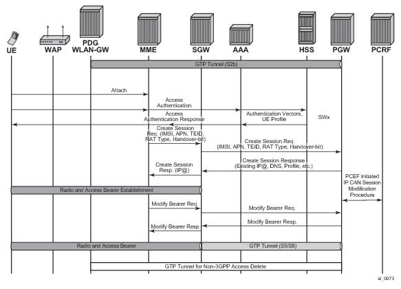
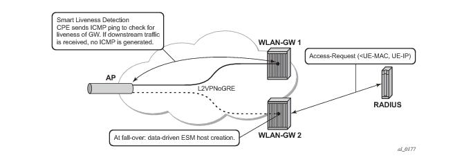
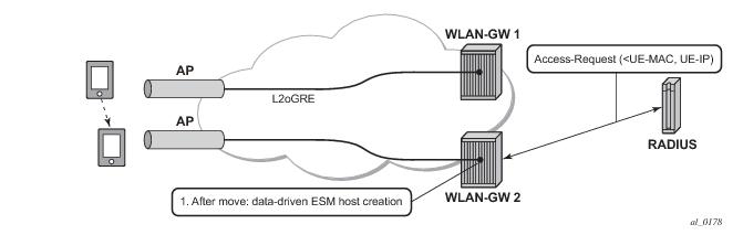
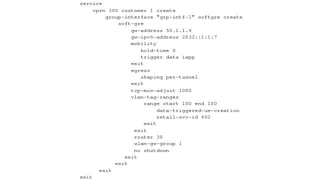
With “data-triggered-ue-creation” configured under soft-GRE group interface or per VLAN range (such as, per one or more SSIDs), first L3 packet received on WLAN-GW ISA from an unknown subscriber (with no prior state, such as an unknown MAC address) will trigger RADIUS authentication from the ISA. The authentication is based on configured isa-radius-policy (under aaa context). If RADIUS authentication succeeds, then ESM host is created from the CPM. The ESM host can get deleted based on idle-timeout. Data-triggered authentication and subscriber creation enables stateless inter WLAN-GW redundancy, as shown in Figure 151. If the AP is configured with a backup WLAN-GW address (or FQDN), it can tunnel subscriber traffic to the backup WLAN-GW, when it detects failure of the primary WLAN-GW (based on periodic liveness detection). With “data-triggered-ue-creation” configured, the first data packet results in authentication and ESM host creation on the backup WLAN-GW. If the subscriber had obtained an IP address via DHCP with L2-aware NAT on the primary WLAN-GW, it can retain it with L2 aware NAT on the backup WLAN-GW. The NAT outside pool for the subscriber changes on the backup WLAN-GW based on local configuration. For a subscriber that needs to be anchored on GGSN/PGW (as indicated via RADIUS access-accept), RADIUS server will return the IP address of PGW/GGSN where the UE was anchored before the switch-over. GTP tunnel is then signaled with “handover indication” set. The PGW/GGSN must return the requested IP address of the UE, which is the address with which the UE originated data packet that triggered authentication.
The same data-triggered authentication and subscriber creation is also used to support inter WLAN-GW mobility, such as when a UE moves form one AP to another AP such that the new AP is anchored on a different WLAN-GW. This is shown in Figure 152.
Figure 151: N:1 WLAN-GW Redundancy Based on “Data-Triggered” Authentication and Subscriber Creation
Figure 152: Inter WLAN-GW Mobility Based on “Data-Triggered” Authentication and Subscriber Creation
output
The following output displays the configuration for migrant user support and “data-triggered” subscriber creation.
#------------------------------------------------------
 NAT configuration for migrant and authenticated users
#------------------------------------------------------
service
 
  vprn 300 customer 1 create
 
     nat
       inside
          l2-aware
               address 21.1.1.1/16
          exit
       exit
       outside
           pool "migrant_outside_pool" nat-group 1 type wlan-gw-anchor create 
                address-range 22.22.0.0 22.22.0.255 create
                exit
                no shutdown
           exit
           pool "wifi_outside_pool" nat-group 1 type l2-aware create 
                address-range 22.0.0.0 22.0.0.255 create
                exit
                no shutdown
           exit
       exit
     exit
  exit
 
  nat
   nat-policy "migrant_nat_300" create
        pool "migrant_outside_pool" router 300
        timeouts
             tcp-established min 1 
        exit
   exit
 
   nat-policy "wifi_nat_300" create
        pool "wifi_outside_pool" router 300
   exit
 
 exit
 
 
#--------------------------------------------------------------------------------
echo "AAA Configuration" - ISA-RADIUS-Policy for authentication from WLAN-GW ISA
#--------------------------------------------------------------------------------
    aaa
        isa-radius-policy "wifi_isa_radius" create
            description "Default authentication policy for migrant users"
            password "i2KzVe9XPxgy4KN2UEIf6jKeMT3X4mT6JcUmnnPZIrw" hash2
            servers
                router "Base"
                source-address-range 100.100.100.4
                server 1 create
                    authentication
                    coa
                    ip-address 100.100.100.2
                    secret "ABIQRobhHXzq13ycwqS74FSrj.OdTwh5IdjhRB.yAF." hash2
                    no shutdown
                exit
            exit
        exit
        radius-server-policy "radius_server_policy" create
            servers
                router "Base"
                server 1 name "radius_server"
            exit
        exit
    exit
 
#--------------------------------------------------
echo "Subscriber-mgmt Configuration" - Redirect Policy
#--------------------------------------------------
    subscriber-mgmt             
        http-redirect-policy "migrant_redirect" create
            url "portal.ipdtest.alcatel-lucent.com:8081/start/?mac=$MAC&url=$URL&ip=$IP"
            portal-hold-time 10
            forward-entries
                dst-ip 8.8.8.1 protocol tcp dst-port 8081
                dst-ip 8.8.8.7 protocol tcp dst-port 8007
                dst-ip 8.8.8.8 protocol udp dst-port 53
            exit
        exit
     exit
service
 
#----------------------------------------------------------------
echo "migrant user configuration under soft-GRE group interface”
#---------------------------------------------------------------
 
  vprn 300 customer 1 create
 
    subscriber-interface "ies-4-20.1.1.1" create
        address 20.1.1.1/16
                
        group-interface "grp-vprn_ue-2/1/2:51" softgre create
            sap-parameters
                sub-sla-mgmt
                    def-sla-profile "slaprof_1"
                    def-sub-profile "subprof_1"
                    sub-ident-policy "identprof"
                 exit
             exit
             dhcp
                 proxy-server
                     emulated-server 20.1.1.1
                     no shutdown
                 exit
                 trusted
                 lease-populate 32767
                 user-db "radius_ludb"
                 no shutdown
              exit
              host-connectivity-verify interval 1000
              soft-gre
                  gw-address 50.1.1.4
                  mobility
                      hold-time 0
                      trigger data iapp 
                  exit
                  router 50
                  wlan-gw-group 1
                  vlan-tag-ranges
                       range start 100 end 100
                            authentication
                                 authentication-policy "wifi_isa_radius"
                            exit
                                                      data-triggered-ue-creation
                            dhcp
                               l2-aware-ip-address 21.1.1.2
 primary-dns 130.1.1.1
             			 secondary-dns 131.1.1.1
                               no shutdown
                            exit
                            nat-policy "migrant_nat_4"
                        exit                                                                                          
    exit
                   no shutdown
                exit
          exit
     exit
exit
 
IPv6-only Access
In order to accommodate IPv6 only AP/CPEs, IPv6 soft GRE tunnel transport, and IPv6 client-side support for RADIUS-proxy have been added.
 
IPv6 GRE Tunnels
Support for IPv6 GRE tunnels require configuration of local IPv6 tunnel end-point address under soft-gre configuration on the group-interface. The transport for L2oGRE (or L2VPNoGRE) packet is IPv6 as shown in Figure 153. The outer IPv6 header contains the value 0x2F (GRE) in its Next Header field. GRE header contains protocol Ethernet (0x6558) or Ethernet-over-MPLS (0x8847) as in the case IPv4 GRE.
Figure 153: IPv6 Transport for L2oGRE Packet
A single soft-gre endpoint instance on the group-interface can have both IPv4 and IPv6 address configured as shown in Figure 154, and inter-AP mobility between IPv4 and IPv6 only APs is supported in this scenario.
Figure 154: IPv6 Endpoint Configuration for Soft-GRE
The data-path for IPv6 GRE tunneled packets, including load-balancing of tunneled packets amongst set of ISAs in the WLAN-GW group, and anchoring after tunnel de-capsulation remains unchanged. Per tunnel traffic shaping is supported similar to IPv4 tunnels. All existing per tunnel configuration on the group-interface described in previous sections (including mobility, egress shaping, VLAN ranges, etc.) is supported identically for IPv6 tunnels. Tunnel reassembly for upstream tunneled traffic is not supported for IPv6 tunnels in this release. TCP mss-adjust is supported for IPv6 tunnels, and is configurable under soft-gre mode on group-interface. APs must use globally routable addresses for GRE IPv6 transport. Packets with extension headers are dropped.
 
IPv6 Client-Side RADIUS Proxy
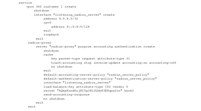
RADIUS proxy is extended to listen for incoming IPv6 RADIUS messages from IPv6 RADIUS clients on AP/CPEs. The listening interface that the RADIUS proxy binds to must be configured with an IPv6 address as shown in Figure 155. The IPv6 RADIUS proxy is solely for DHCPv4-based UEs behind IPv6 only AP/CPEs (IPv6-capable UEs are not supported in this release). All RADIUS-proxy functions (including caching, correlation with DHCPv4, and mobility tracking) are supported identically to existing IPv4 client-side RADIUS-proxy.
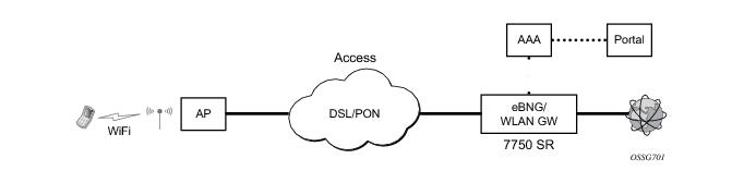
Figure 155: Configuration for IPv6 Client-Side RADIUS Proxy