For feedback, use the following:
ipd_online_feedback@alcatel-lucent.com
Table of Contents Previous Next Index PDF


Introduction to Triple Play
In This Section
This section provides an overview of the 7750 SR services, service model and service entities used in conjunction with Triple Play services only to the relevant service types. Details about services, configurations, and CLI syntax can be found in the 7750 SR OS Services Guide.
Topics in this section include:
Alcatel-Lucent’s Triple Play Service Delivery Architecture
 
Introduction to Triple Play
For more than a decade, telephony service providers have considered offering video services to residential customers. However, in the past it was not economically nor technically feasible to launch the implementation on a large scale.
Recently, several technical trends and evolutions have propelled video delivery to the foreground, including:
Traditional cable operators began offering television services and later added Internet access and telephony to their offerings. Conversely, traditional telephony operators such as RBOCS, PTTs, have also added Internet access, and many are now in the process of also adding video delivery.
This bundling of video, voice, and data services to residential subscribers is now commonly known as Triple Play services. The video component always includes linear programming (broadcast television), but often also has a non-linear Video on Demand (VoD) component.
 
Blueprint for Optimizing Triple Play Service Infrastructures
Alcatel-Lucent's TPSDA allows network operators to progressively integrate their HSI, voice, and video services within a unified and homogeneous Ethernet-based aggregation network environment. The key benefits of the proposed service infrastructure include cost optimization, reduced risk, and accelerated time to market for new services.
At a high level, TPSDA implements:
 
Architectural Foundations
With 7750 SR OS, the architectural foundations of Alcatel-Lucent’s TPSDA established in previous releases is reinforced while its applicability is expanded to encompass many new deployment models and support Any Mode of Operation (AMO). Through these enhancements, TPSDA becomes more universally deployable and flexible in addressing the specifics of any provider’s network/rollout.
Alcatel-Lucent has defined new terminologies that have been adopted industry-wide, including:
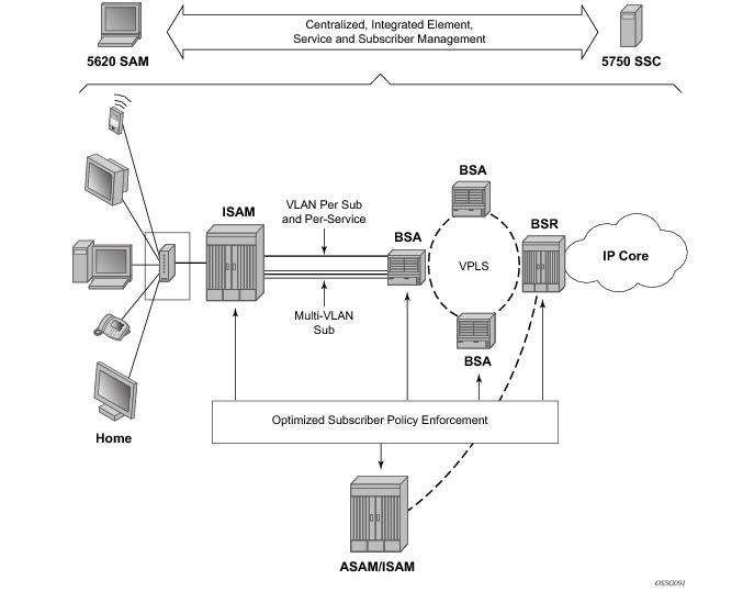
Figure 1 depicts TPSDA’s centralized, integrated element, service and subscriber management architecture.
Figure 1: Triple Play Service Delivery Architecture
 
Optimizing Triple Play Service Infrastructures
More than a branding exercise, new terminologies signal a significant shift from “best effort” and traditional DSLAMs, Ethernet switches and BRASs, in the sense that they capture a shift in required characteristics and capabilities for a new generation of service rollouts, including:
Alcatel-Lucent’s Triple Play Service Delivery Architecture (TPSDA) advocates the optimal distribution of service intelligence over the BSAN, BSA and BSR, rather than concentrating on fully centralized or decentralized BRAS models which artificially define arbitrary policy enforcement points in the network. With 7750 SR OS, the optimized enforcement of subscriber policies across nodes or over a single node (as dictated by evolving traffic patterns), allows a more flexible, optimized, and cost-effective deployment of services in a network, guaranteeing high quality and reliable delivery of all services to the user.
With TPSDA, network economics, subscriber density, network topologies and subscriber viewership patterns define the optimal policy enforcement point for each policy type (security, QoS, multicasting, anti-spoofing, filtering etc.). The 7750 SR OS capabilities allow service providers to support any mode of operation, including any combination of access methods, home gateway type, and policy enforcement point (BSAN, BSA or BSR or a combination of the three).
All of the 7750 SR OS and Alcatel-Lucent’s 5750 SSC’s subscriber policy enforcement and management capabilities described in this section build upon Alcatel-Lucent’s TPSDA extensive capabilities and provide key capabilities in the following areas:
 
Distributed Service Edges
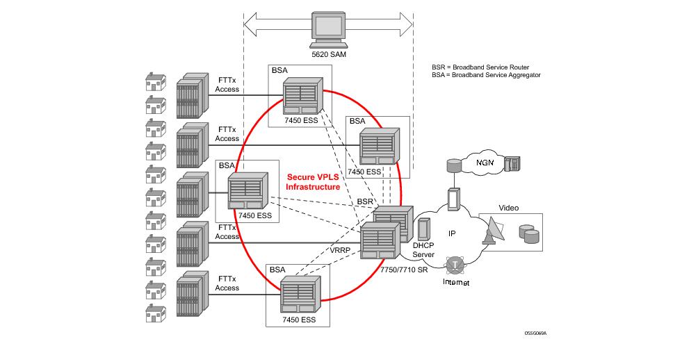
The TPSDA architecture (Figure 2), is based on two major network elements optimized for their respective roles, the Broadband Service Aggregator (BSA) and the Broadband Service Router (BSR). An important characteristic of BSAs and BSRs is that they effectively form a distributed virtual node with the BSAs performing subscriber-specific functions where the various functions scale, and the BSRs providing the routing intelligence where it is most cost-effective.
The Alcatel-Lucent 7450 ESS and 7750/7710 SR Series, respectively, provide the BSA and BSR functionalities in TPSDA. Both are managed as a single virtual node using Alcatel-Lucent's 5620 Service Aware manager (SAM), which provides a unified interface for streamlined service and policy activation across the distributed elements of the TPSDA architecture, including VPLS, QoS, multicasting, security, filtering and accounting.
Figure 2: Alcatel-Lucent’s Triple Play Service Delivery Architecture
Digital subscriber line access multiplexers (DSLAMs) or other access nodes are connected to Ethernet access ports on the BSA. Typically a single VLAN per subscriber is configured between the access node and the BSA. A VLAN per subscriber provides a persistent context against which per-subscriber policies (QoS, filtering, accounting) can be applied in the BSA.
Scaling of traffic and services is achieved by dividing the Layer 2 and Layer 3 functions between the BSA and BSR and by distributing key service delivery functions. BSAs are more distributed than BSRs, cost-effectively scaling per-subscriber policy enforcement.
The BSA is a high-capacity Ethernet-centric aggregation device that supports hundreds of Gigabit Ethernet ports, tens of thousands of filter policies, and tens of thousands of queues. The BSA incorporates wire speed security, per-subscriber service queuing, scheduling, accounting, and filtering.
BSAs aggregate traffic for all services towards the BSR. The BSR terminates the Layer 2 access and routes over IP/MPLS (Multi Protocol Label Switching) with support for a full set of MPLS and IP routing protocols, including multicast routing. The BSR supports hundreds of ports and sophisticated QoS for per-service and per-content/source differentiation.
The connectivity between BSAs and BSRs is a Layer 2 forwarding model shown in Figure 2 above as a secure VPLS infrastructure. This refers to the fact that the BSA-BSR interconnections form a multipoint Ethernet network with security extensions to prevent unauthorized communication, denial of service, and theft of service. One of the advantages of using VPLS for this application is that VPLS instances can be automatically established over both ‘hub and spoke’ and ring topologies providing sub-50 ms resilience. Regardless of the fiber plant layout, VPLS enables a full mesh to be created between BSA and BSR nodes, ensuring efficient traffic distribution and resilience to node or fiber failure.
Other unique features of the BSA and BSR that contribute to this secure VPLS infrastructure are:
1.
2. RSHG combined with the ARP reply agent perform ARP and broadcast suppression to ensure that addressing information is restricted;
3. Protection against theft of service and denial of service is provided by MAC and/or IP filters automatically populated using DHCP snooping, and by MAC pinning;
4. Using the RADIUS interface, is possible to perform RADIUS authentication of users before allowing a DHCP discover to progress into the network.
 
Service Differentiation, QoS Enablement
Alcatel-Lucent's TPSDA approach provides a model based on call admission for video and VoIP, with the need to guarantee delay/jitter/loss characteristics once the service connection is accepted. The architecture also meets the different QoS needs of HSI, namely per-subscriber bandwidth controls, including shaping and policing functions that have little or no value for video and VoIP services. In conjunction with the architecture's support for content differentiation, this enables differentiated service pricing within HSI.
The distribution of QoS policy and enforcement across BSA and BSR allows the service provider to implement meaningful per-subscriber service level controls. Sophisticated and granular QoS in the BSA allows the service provider to deliver truly differentiated IP services based on the subscriber as well as on the content.
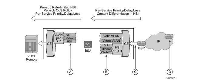
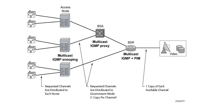
In the BSR to BSA downstream direction (Figure 3), IP services rely on IP layer classification of traffic from the network to queue traffic appropriately towards the BSA. Under extreme loading (only expected to occur under network fault conditions), lower priority data services and/or HSI traffic will be compromised in order to protect video and voice traffic. Classification of HSI traffic based on source network address or IEEE 802.1p marking allows the QoS information to be propagated to upstream or downstream nodes by network elements. Refer to Table 3 for the descriptions.
The BSR performs service distribution routing based on guarantees required to deliver the service and associated content, rather than on individual subscribers. The BSR only needs to classify content based on the required forwarding class for a given BSA to ensure that each service's traffic receives the appropriate treatment towards the BSA.
 
Figure 3: Downstream QoS Enablement
 
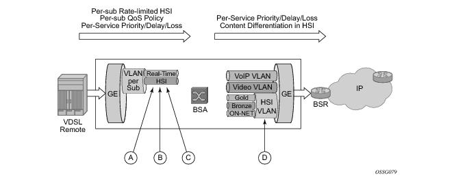
In the upstream direction (BSA to BSR. Figure 4), traffic levels are substantially lower. Class-based queuing is used on the BSA network interface to ensure that video control traffic is propagated with a minimal and consistent delay, and that preferred data/HSI services receive better treatment for upstream/peering service traffic than the best effort Internet class of service.
Note that the IP edge is no longer burdened with enforcing per-subscriber policies for hundreds of thousands of users. This function is now distributed to the BSAs, and the per-subscriber policies can be implemented on the interfaces directly facing the access nodes.
Figure 4: Upstream QoS Enablement
 
The BSA is capable of scheduling and queuing functions on a per-service, per-subscriber basis, in addition to performing wire-speed packet classification and filtering based on both Layer 2 and Layer 3 fields.
Each subscriber interface provides at least three dedicated queues. TPSDA makes it possible to configure these queues such that the forwarding classes defined for all services can all be mapped to one service VLAN upstream. In the BSA, assuming hundreds of subscribers per Gigabit Ethernet interface, this translates to a thousand or more queues per port.
In addition to per-service rate limiting for HSI services, each subscriber's service traffic can be rate limited as an aggregate using a bundled service policy. This allows different subscribers to receive different service levels independently and simultaneously.
Distributed multicasting today's predominant video service is broadcast TV, and will likely remain significant for a long time. As video services are introduced, it is sensible to optimize investments by matching resources to the service model relevant at the time. Consequently, the objective of the service infrastructure should be to incorporate sufficient flexibility to optimize for broadcast TV in the short term, yet scale to support a full unicast (VoD) model as video service offerings evolve.
Optimizing for broadcast TV means implementing multicast packet replication throughout the network. Multicast improves the efficiency of the network by reducing the bandwidth and fiber needed to deliver broadcast channels to the subscriber. A multicasting node can receive a single copy of a broadcast channel and replicate it to any downstream nodes that require it, substantially reducing the required network resources. This efficiency becomes increasingly important closer to the subscriber. Multicast should be performed at each or either of the access, aggregation, and video edge nodes.
Multicasting as close as possible to the subscriber has other benefits since it enables a large number of users to view the content concurrently. The challenges of video services are often encountered in the boundary cases, such as live sports events and breaking news, for which virtually all the subscribers may be watching just a few channels. These exceptional cases generally involve live content, which is true broadcast content. Multicasting throughout the network makes it possible to deliver content under these circumstances while simplifying the engineering of the network.
Efficient multicasting requires the distribution of functions throughout the access and the aggregation network to avoid overloading the network capacity with unnecessary traffic. TPSDA realizes efficient multicasting by implementing IGMP snooping in the access nodes, IGMP snooping in the BSA and multicast routing in the BSR (Figure 5).
Figure 5: Distributed Multicasting in TPSDA
 
Virtual MAC Subnetting for VPLS
This feature allows, at the VPLS instance level, MAC subnetting, such as learning and switching based on a configurable number of bits from the source MAC address and from the destination MAC, respectively. This considerably reduces the VPLS FIB size.
MAC scalability involving MAC learning and switching based on the first x bits of a virtual MAC address is suitable in an environment where some MAC addresses can be aggregated based on a common first x bits, for example 28 out of 48. This can be deployed in a TPSDA environment where the VPLS is used for pure aggregation (there is no subscriber management) between the DSLAM and BRAS devices. The DSLAMs must be able to map customer MAC addresses to a pool of internal virtual MAC addresses where the first bits (28, for example) identify the DSLAM with the next 20 bits identifying, the DSLAM slot, port number, and customer MAC station on that port. The VPLS instance(s) in the PE distinguishes only between different DSLAMs connected to it. They need to learn and switch based only on the first 28 bits of the MAC address allowing scaling of the FIB size in the PE.
Figure 6: Subnetting Topology
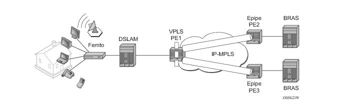
Figure 6 displays a Layer 2 PE network (such as the 7450 ESS) aggregating traffic from DSLAMs (Alcatel-Lucent) to BRAS devices. The VPLS service is running in the PEs directly connected to the DSLAMs (VPLS PE1) while the PEs connected to the BRAS devices are running a point-to-point Layer 2 service (Epipe).
Alcatel-Lucent DSLAMs have the capability to map every customer MAC to a service provider MAC using the virtual MAC addressing scheme depicted in Figure 7.
Figure 7: VMAC Subnetting Topology
As the packet ingresses the DSLAM from the residential customer, the source MAC address (a customer MAC for one of its terminals/routers) is replaced by the DSLAM with a virtual MAC using the format depicted in Figure 7.
Based on this scheme, it is apparent that the VMACs from one DSLAM have bits 47-21 in common.
The VPLS instance in PE1 only learns the first part of the MAC (bits 47 — 21) and, as the packets arrive from the BRAS device, switches based only on these bits in the destination MAC address to differentiate between the connected DSLAMs. Once the packet arrives at the DSLAM, the entire destination MAC is checked to determine the slot, port and which specific customer station the packet is destined to. As the packet is sent to the customer, the DSLAM replaces the destination MAC address with the actual customer MAC corresponding to the customer station.
 
The following are VPLS features not supported when the VMAC subnetting feature is enabled:
Services
A service is a globally unique entity that refers to a type of connectivity service for either Internet or VPN connectivity. Each service is uniquely identified by a service ID within a service area. The 7750 SR service model uses logical service entities to construct a service. In the service model, logical service entities are provide a uniform, service-centric configuration, management, and billing model for service provisioning.
Services can provide Layer 2/bridged service or Layer3/IP routed connectivity between a service access point (SAP) on one 7750 SR router and another service access point (a SAP is where traffic enters and exits the service) on the same (local) or another 7750 SR router (distributed). A distributed service spans more than one router.
Distributed services use service distribution points (SDPs) to direct traffic to another 7750 SR through a service tunnel. SDPs are created on each participating 7750 SR, specifying the origination address (the 7750 SR router participating in the service communication) and the destination address of another SR-Series. SDPs are then bound to a specific customer service. Without the binding process, far-end 7750 SR devices are not able to participate in the service (there is no service without associating an SDP with a service).
 
Service Types
The 7750 SR offers the following types of subscriber services which are described in more detail in the referenced chapters:
 
Service Policies
Common to all 7750 SR connectivity services are policies that are assigned to the service. Policies are defined at a global level and then applied to a service on the router. Policies are used to define 7750 SR service enhancements. The types of policies that are common to all 7750 SR connectivity services are:
QoS ingress and egress policies determine the QoS characteristics for a SAP. A QoS policy applied to a SAP specifies the number of queues, queue characteristics (such as forwarding class, committed, and peak information rates, etc.) and the mapping of traffic to a forwarding class. A QoS policy must be created before it can be applied to a SAP. A single ingress and a single egress QoS policy can be associated with a SAP.
Filter policies, also referred to as access control lists (ACLs), control the traffic allowed in or out of a SAP based on MAC or IP match criteria. Associating a filter policy on a SAP is optional. Filter policies are identified by a unique filter policy ID. A filter policy must be created before it can be applied to a SAP. A single ingress and single egress filter policy can be associated with a SAP.
The 7750 SR routers provide a comprehensive set of service-related counters. Accounting data can be collected on a per-service, per-forwarding class basis, which enables network operators to accurately measure network usage and bill each customer for each individual service using any of a number of different billing models.
­Alcatel-Lucent Service Model
Topics in this section:
 
Introduction
In the 7750 SR service model, the 7750 SR service edge routers are deployed at the provider edge. Services are provisioned on 7750 SRs and transported across an IP and/or IP/MPLS provider core network in encapsulation tunnels created using Generic Router Encapsulation (GRE) or MPLS Label Switched Paths (LSPs).
The service model uses logical service entities to construct a service. The logical service entities are designed to provide a uniform, service-centric configuration, management, and billing model for service provisioning. Some benefits of this service-centric design include:
Service provisioning uses logical entities to provision a service where additional properties can be configured for bandwidth provisioning, QoS, security filtering, accounting/billing to the appropriate entity.
 
Service Entities
The basic logical entities in the service model used to construct a service are:
Customers (see )
Service Distribution Points (SDPs) (see ) (for distributed services only)
Figure 8: Alcatel-Lucent’s Service Entities
 
Customers
The terms customers and subscribers are used synonymously. The most basic required entity is the customer ID value which is assigned when the customer account is created. To provision a service, a customer ID must be associated with the service at the time of service creation.
 
Service Access Points (SAPs)
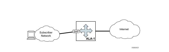
Each subscriber service type is configured with at least one service access point (SAP). A SAP identifies the customer interface point for a service on an ­Alcatel-Lucent 7750 SR router (Figure 9). The SAP configuration requires that slot, MDA, and port/channel information be specified. The slot, MDA, and port/channel parameters must be configured prior to provisioning a service (see the Cards, MDAs, and Ports section of the 7750 SR OS Interface Configuration Guide).
A SAP is a local entity to the 7750 SR and is uniquely identified by:
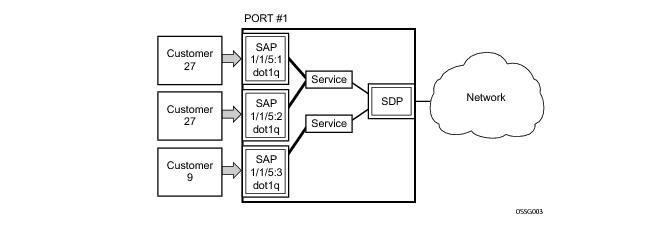
Depending on the encapsulation, a physical port or channel can have more than one SAP associated with it. SAPs can only be created on ports or channels designated as “access” in the physical port configuration. SAPs cannot be created on ports designated as core-facing “network” ports as these ports have a different set of features enabled in software.
Figure 9: Service Access Point (SAP)
 
SAP Encapsulation Types and Identifiers
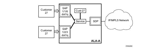
The encapsulation type is an access property of a service Ethernet port or SONET/SDH or TDM channel. The appropriate encapsulation type for the port or channel depends on the requirements to support multiple services on a single port/channel on the associated SAP and the capabilities of the downstream equipment connected to the port/channel. For example, a port can be tagged with IEEE 802.1Q (referred to as dot1q) encapsulation in which each individual tag can be identified with a service. A SAP is created on a given port or channel by identifying the service with a specific encapsulation ID.
 
Ethernet Encapsulations
The following lists encapsulation service options on Ethernet ports:
1
2
Dot1q — Supports multiple services for one customer or services for multiple customers (Figure 10). For example, the port is connected to a multi-tenant unit (MTU) device with multiple downstream customers. The encapsulation ID used to distinguish an individual service is the VLAN ID in the IEEE 802.1Q header.
3
In the dot1q and q-in-q options, traffic encapsulated with tags for which there is no definition are discarded.
Figure 10: Multiple SAPs on a Single Port/Channel
 
SAP Considerations
When configuring a SAP, consider the following:
A port/channel with a dot1q or BCP-dot1q encapsulation type means the traffic for the SAP is identified based on a specific IEEE 802.1Q VLAN ID value. The VLAN ID is stripped off at SAP ingress and the appropriate VLAN ID placed on at SAP egress. As a result, VLAN IDs only have local significance, so the VLAN IDs for the SAPs for a service need not be the same at each SAP.
If a port/channel is administratively shutdown, all SAPs on that port/channel will be operationally out of service.
 
Service Distribution Points (SDPs)
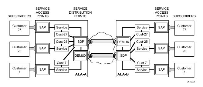
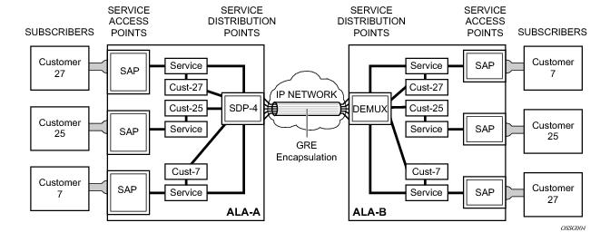
A service distribution point (SDP) acts as a logical way to direct traffic from one 7750 SR to another 7750 SR through a uni-directional (one-way) service tunnel. The SDP terminates at the far-end 7750 SR which directs packets to the correct service egress SAPs on that device. A distributed service consists of a configuration with at least one SAP on a local node, one SAP on a remote node, and an SDP binding the service to the service tunnel.
An SDP has the following characteristics:
An SDP is locally unique to a participating 7750 SR. The same SDP ID can appear on other 7750 SR routers.
An SDP from the local device to a far-end 7750 SR requires a return path SDP from the far-end 7750 SR back to the local 7750 SR. Each device must have an SDP defined for every remote router to which it wants to provide service. SDPs must be created first, before a distributed service can be configured.
 
SDP Binding
To configure a distributed service from ALA-A to ALA-B, the SDP ID (4) (Figure 11) must be specified in the service creation process in order to “bind” the service to the tunnel (the SDP). Otherwise, service traffic is not directed to a far-end point and the far-end 7750 SR device(s) cannot participate in the service (there is no service).
Figure 11: A GRE Service Distribution Point (SDP) pointing from ALA-A to ALA-B
 
Spoke and Mesh SDPs
When an SDP is bound to a service, it is bound as either a spoke SDP or a mesh SDP. The type of SDP indicates how flooded traffic is transmitted.
A spoke SDP is treated like the equivalent of a traditional bridge “port” where flooded traffic received on the spoke SDP is replicated on all other “ports” (other spoke and mesh SDPs or SAPs) and not transmitted on the port it was received.
All mesh SDPs bound to a service are logically treated like a single bridge “port” for flooded traffic where flooded traffic received on any mesh SDP on the service is replicated to other “ports” (spoke SDPs and SAPs) and not transmitted on any mesh SDPs.
 
SDP Encapsulation Types
The ­Alcatel-Lucent service model uses encapsulation tunnels through the core to interconnect 7750 SR service edge routers. An SDP is a logical way of referencing the entrance to an encapsulation tunnel.
The following encapsulation types are supported:
 
GRE
GRE encapsulated tunnels have very low overhead and are best used for Best-Effort class of service. Packets within the GRE tunnel follow the Interior Gateway Protocol (IGP) shortest path from edge to edge. If a failure occurs within the service core network, the tunnel will only converge as fast as the IGP itself. If Equal Cost Multi-Path (ECMP) routing is used in the core, many loss-of-service failures can be minimized to sub-second timeframes.
 
MPLS
Multi-Protocol Label Switching (MPLS) encapsulation has the following characteristics:
Paths can be manually defined or a constraint-based routing protocol (e.g., OSPF-TE or CSPF) can be used to determine the best path with specific constraints.
A 7750 SR router supports both signaled and non-signaled LSPs through the network.
Because services are carried in encapsulation tunnels and an SDP is an entrance to the tunnel, an SDP has an implicit Maximum Transmission Unit (MTU) value. The MTU for the service tunnel can affect and interact with the MTU supported on the physical port where the SAP is defined.
 
SDP Keepalives
SDP keepalives are a way of actively monitoring the SDP operational state using periodic ­Alcatel-Lucent SDP Ping Echo Request and Echo Reply messages. ­Alcatel-Lucent SDP Ping is a part of Alcatel-Lucent’s suite of Service Diagnostics built on an ­Alcatel-Lucent service-level OA&M protocol. When SDP Ping is used in the SDP keepalive application, the SDP Echo Request and Echo Reply messages are a mechanism for exchanging far-end SDP status.
Configuring SDP keepalives on a given SDP is optional. SDP keepalives for a particular SDP have the following configurable parameters:
SDP keepalive Echo Request messages are only sent when the SDP is completely configured and administratively up and SDP keepalives is administratively up. If the SDP is administratively down, keepalives for the SDP are disabled.
SDP keepalive Echo Request messages are sent out periodically based on the configured Hello Time. An optional Message Length for the Echo Request can be configured. If Max Drop Count Echo Request messages do not receive an Echo Reply, the SDP will immediately be brought operationally down.
If a keepalive response is received that indicates an error condition, the SDP will immediately be brought operationally down.
Once a response is received that indicates the error has cleared and the Hold Down Time interval has expired, the SDP will be eligible to be put into the operationally up state. If no other condition prevents the operational change, the SDP will enter the operational state.
Epipe Service Overview
An Epipe service is ­Alcatel-Lucent’s implementations of an Ethernet VLL based on the IETF “Martini Drafts” (draft-martini-l2circuit-trans-mpls-08.txt and draft-martini-l2circuit-encapmpls-04.txt) and the IETF Ethernet Pseudo-wire Draft (draft-so-pwe3-ethernet-00.txt).
An Epipe service is a Layer 2 point-to-point service where the customer data is encapsulated and transported across a service provider’s IP or MPLS network. An Epipe service is completely transparent to the subscriber’s data and protocols. The 7750 SR Epipe service does not perform any MAC learning. A local Epipe service consists of two SAPs on the same node, whereas a distributed Epipe service consists of two SAPs on different nodes. SDPs are not used in local Epipe services.
Each SAP configuration includes a specific port/channel on which service traffic enters the 7750 SR from the customer side (also called the access side). Each port is configured with an encapsulation type. If a port is configured with an IEEE 802.1Q (referred to as dot1q) encapsulation, then a unique encapsulation value (ID) must be specified.
Figure 12: Epipe/VLL Service
 
VPLS Service Overview
Virtual Private LAN Service (VPLS) as described in Internet Draft draft-ietf-ppvpn-vpls-ldp-01.txt, is a class of virtual private network service that allows the connection of multiple sites in a single bridged domain over a provider-managed IP/MPLS network. The customer sites in a VPLS instance appear to be on the same LAN, regardless of their location. VPLS uses an Ethernet interface on the customer-facing (access) side which simplifies the LAN/WAN boundary and allows for rapid and flexible service provisioning.
VPLS offers a balance between point-to-point Frame Relay service and outsourced routed services (VPRN). VPLS enables each customer to maintain control of their own routing strategies. All customer routers in the VPLS service are part of the same subnet (LAN) which simplifies the IP addressing plan, especially when compared to a mesh constructed from many separate point-to-point connections. The VPLS service management is simplified since the service is not aware of nor participates in the IP addressing and routing.
A VPLS service provides connectivity between two or more SAPs on one (which is considered a local service) or more (which is considered a distributed service) 7750 SR routers. The connection appears to be a bridged domain to the customer sites so protocols, including routing protocols, can traverse the VPLS service.
Other VPLS advantages include:
For details on VPLS, including a packet walkthrough, refer to VPLS section in the SR-OS Services Guide.
 
Split Horizon SAP Groups and Split Horizon Spoke SDP Groups
Within the context of VPLS services, a loop-free topology within a fully meshed VPLS core is achieved by applying split-horizon forwarding concept that packets received from a mesh SDP are never forwarded to other mesh SDPs within the same service. The advantage of this approach is that no protocol is required to detect loops within the VPLS core network.
In applications such as DSL aggregation, it is useful to extend this split-horizon concept also to groups of SAPs and/or spoke SDPs. This extension is referred to as a split horizon SAP group or residential bridging.
Traffic arriving on a SAP or a spoke SDP within a split horizon group will not be copied to other SAPs and spoke SDPs in the same split horizon group (but will be copied to SAPs / spoke SDPs in other split horizon groups if these exist within the same VPLS).
 
Residential Split Horizon Groups
To improve the scalability of a SAP-per-subscriber model in the broadband services aggregator (BSA), the 7750 SR supports a variant of split horizon groups called residential split horizon groups (RSHG).
A RSHG is a group of split horizon group SAPs with following limitations:
Spoke SDPs can also be members of a RSHG VPLS. The downstream multicast traffic restriction does not apply to spoke SDPs.
IES Service Overview
Internet Enhanced Service (IES) is a routed connectivity service where the subscriber communicates with an IP router interface to send and receive Internet traffic. An IES has one or more logical IP routing interfaces each with a SAP which acts as the access point to the subscriber’s network. IES allow customer-facing IP interfaces to participate in the same routing instance used for service network core routing connectivity. IES services require that the IP addressing scheme used by the subscriber be unique between other provider addressing schemes and potentially the entire Internet.
While IES is part of the routing domain, the usable IP address space may be limited. This allows a portion of the service provider address space to be reserved for service IP provisioning, and be administered by a separate but subordinate address authority.
IP interfaces defined within the context of an IES service must have a SAP associated as the access point to the subscriber network. Multiple IES services are created to segregate subscriber-owned IP interfaces.
Figure 13: Internet Enhanced Service
The IES service provides Internet connectivity. Other features include:
 
 
IP Interface
IES customer IP interfaces can be configured with most of the same options found on the core IP interfaces. The advanced configuration options supported are:
Configuration options found on core IP interfaces not supported on IES IP interfaces are:
VPRN Service Overview
RFC2547bis is an extension to the original RFC 2547, which details a method of distributing routing information and forwarding data to provide a Layer 3 Virtual Private Network (VPN) service to end customers.
Each Virtual Private Routed Network (VPRN) consists of a set of customer sites connected to one or more PE routers. Each associated PE router maintains a separate IP forwarding table for each VPRN. Additionally, the PE routers exchange the routing information configured or learned from all customer sites via MP-BGP peering. Each route exchanged via the MP-BGP protocol includes a Route Distinguisher (RD), which identifies the VPRN association.
The service provider uses BGP to exchange the routes of a particular VPN among the PE routers that are attached to that VPN. This is done in a way which ensures that routes from different VPNs remain distinct and separate, even if two VPNs have an overlapping address space. The PE routers distribute routes from other CE routers in that VPN to the CE routers in a particular VPN. Since the CE routers do not peer with each other there is no overlay visible to the VPN's routing algorithm.
When BGP distributes a VPN route, it also distributes an MPLS label for that route. On a SR-Series, a single label is assigned to all routes in a VPN.
Before a customer data packet travels across the service provider's backbone, it is encapsulated with the MPLS label that corresponds, in the customer's VPN, to the route which best matches the packet's destination address. The MPLS packet is further encapsulated with either another MPLS label or GRE tunnel header, so that it gets tunneled across the backbone to the proper PE router. Each route exchanged by the MP-BGP protocol includes a route distinguisher (RD), which identifies the VPRN association. Thus the backbone core routers do not need to know the VPN routes.
Deploying and Provisioning Services
The service model provides a logical and uniform way of constructing connectivity services. The basic steps for deploying and provisioning services can be broken down into three phases.
 
Phase 1: Core Network Construction
Before the services are provisioned, the following tasks should be completed:
 
Phase 2: Service Administration
Perform preliminary policy and SDP configurations to control traffic flow, operator access, and to manage fault conditions and alarm messages, the following tasks should be completed:
 
Phase 3: Service Provisioning
Provision the customer services on the 7750 SR service edge routers by defining SAPs, binding policies to the SAPs, and then binding the service to appropriate SDPs as necessary.
Configuration Notes
This section describes service configuration caveats.
 
General
Service provisioning tasks can be logically separated into two main functional areas, core tasks and subscriber tasks and are typically performed prior to provisioning a subscriber service.
Core tasks include the following:
Subscriber services tasks include the following: