For feedback, use the following:
ipd_online_feedback@alcatel-lucent.com
Table of Contents Previous Next Index PDF


Mirror Services
In This Chapter
This chapter provides information to configure mirroring.
Topics in this chapter include:
Service Mirroring
When troubleshooting complex operational problems, customer packets can be examined as they traverse the network. ­Alcatel-Lucent’s service mirroring provides the capability to mirror customer packets to allow for trouble shooting and offline analysis. One way to accomplish this is with an overlay of network analyzers established at multiple PoPs, together with skilled technicians to operate them to decode the data provided. This method of traffic mirroring often requires setting up complex filters in multiple switches and/or routers. These, at best, are only able to mirror from one port to another on the same device.
­Alcatel-Lucent’s service mirroring extends and integrates these capabilities into the network and provides significant operational benefits. Each 7750 SR-Series can mirror packets from a specific service to any destination point in the network, regardless of interface type or speed.
This capability also extends beyond troubleshooting services. Telephone companies have the ability to obtain itemized calling records and wire-taps where legally required by investigating authorities. The process can be very complex and costly to carry out on data networks. Service Mirroring greatly simplifies these tasks, as well as reduces costs through centralization of analysis tools and skilled technicians.
­Alcatel-Lucent’s 7750 SR-Series routers support service-based mirroring. While some Layer 3 switches and routers can mirror on a per-port basis within the device, ­Alcatel-Lucent 7750 SR-Series routers can mirror on an n-to-1 unidirectional service basis and re-encapsulate the mirrored data for transport through the core network to another location, using either IP or MPLS tunneling as required (Figure 1).
Original packets are forwarded while a copy is sent out the mirrored port to the mirroring (destination) port. Service mirroring allows an operator to see the actual traffic on a customer’s service with a sniffer sitting in a central location. In many cases, this reduces the need for a separate, costly overlay sniffer network.
The mirrored frame size that is to be transmitted to the mirror destination can be explicitly configured by using slicing features. This enables mirroring only the parts needed for analysis. For example, only the headers can be copied for analysis, protecting the integrity and security of customer data, or conversely, copying the full packet, including customer data.
Figure 1: Service Mirroring
Mirror Implementation
Mirroring can be implemented on ingress service access points (SAPs) or ingress network interfaces. The Flexible Fast Path processing complexes preserve the ingress packet throughout the forwarding and mirroring process, making incremental packet changes on a separate copy.
­Alcatel-Lucent’s implementation of packet mirroring is based on the following assumptions:
Ingress and egress packets are mirrored as they appear on the wire. This is important for troubleshooting encapsulation and protocol issues.
When mirroring at ingress, the Flexible Fast Path network processor array (NPA) sends an exact copy of the original ingress packet is sent to the mirror destination while normal forwarding proceeds on the original packet.
When mirroring is at egress, the system performs normal packet handling on the egress packet, encapsulating it for the destination interface. A copy of the forwarded packet (as seen on the wire) is forwarded to the mirror destination.
Remote destinations are reached by encapsulating the ingress or egress packet within an SDP, like the traffic for distributed VPN connectivity services. At the remote destination, the tunnel encapsulation is removed and the packet is forwarded out a local SAP.
 
Mirror Source and Destinations
Mirror sources and destinations have the following characteristics:
They can be on the same SROS router (local) or on two different routers (remote).
Mirror destinations can terminate on egress virtual ports which allows multiple mirror destinations to send to the same packet decode device, delimited by IEEE 802.1Q (referred to as Dot1q) tags. This is helpful when troubleshooting a multi-port issue within the network.
When multiple mirror destinations terminate on the same egress port, the individual dot1q tags can provide a DTE/DCE separation between the mirror sources.
Packets ingressing a port can have a mirror destination separate from packets egressing another or the same port (the ports can be on separate nodes).
 
Local and Remote Mirroring
Mirrored frames can be copied and sent to a specific local destination or service on the router (local mirroring) or copies can be encapsulated and sent to a different 7750 SR router (remote mirroring). This functionality allows network operators to centralize not only network analyzer (sniffer) resources, but also the technical staff who operate them.
The router allows multiple concurrent mirroring sessions so traffic from more than one ingress mirror source can be mirrored to the same or different egress mirror destinations.
Remote mirroring uses a service distribution path (SDP) which acts as a logical way of directing traffic from one router to another through a uni-directional (one-way) service tunnel. The SDP terminates at the far-end router which directs packets to the correct destination on that device.
The SDP configuration from the mirrored device to a far-end router requires a return path SDP from the far-end router back to the mirrored router. Each device must have an SDP defined for every remote router to which it wants to provide mirroring services. SDPs must be created first, before services can be configured.
 
Slicing
A further service mirroring refinement is “slicing” which copies a specified packet size of each frame. This is useful to monitor network usage without having to copy the actual data. Slicing enables mirroring larger frames than the destination packet decode equipment can handle. It also allows conservation of mirroring resources by limiting the size of the stream of packet through the router and the core network.
When a mirror slice-size is defined, a threshold that truncates a mirrored frame to a specific size is created. For example, if the value of 256 bytes is defined, up to the first 256 bytes of the frame are transmitted to the mirror destination. The original frame is not affected by the truncation. Mirrored frames, most likely, will grow larger as encapsulations are added when packets are transmitted through the network core or out the mirror destination SAP to the packet/protocol decode equipment. Note that slice-size is not supported by CEM encap-types or IP-mirroring.
The transmission of a sliced or non-sliced frame is also dependent on the mirror destination SDP path MTU and/or the mirror destination SAP physical MTU. Packets that require a larger MTU than the mirroring destination supports are discarded if the defined slice size does not truncate the packet to an acceptable size.
 
Mirroring Performance
Replication of mirrored packets can, typically, affect performance and should be used carefully. ­Alcatel-Lucent 7750 SR-Series routers minimize the impact of mirroring on performance by taking advantage of its distributed Flexible Fast Path technology. Flexible Fast Path forwarding allows efficient mirror service scaling and, at the same time, allows a large amount of data to be mirrored with minimal performance impact. When a mirror destination is configured, the packet slice option can truncate mirrored packets to the destination, which minimizes replication and tunneling overhead.
Mirroring can be performed based on the following criteria:
 
Mirroring Configuration
Configuring mirroring is similar to creating a uni-direction service. Mirroring requires the configuration of:
Figure 2 depicts a local mirror service configured on ALA-A.
SAP 2/1/3 is specified as the destination. The sniffer is physically connected to this port. Mirrored traffic ingressing and egressing port 2/1/2 is sent here. SAP, encapsulation requirements, packet slicing, and mirror classification parameters are configured. SDPs are not used in local mirroring.
Figure 2: Local Mirroring Example
Figure 3 depicts a remote mirror service configured as ALA B as the mirror source and ALA A as the mirror destination. Mirrored traffic ingressing and egressing port 5/2/1 (the source) on ALA B is handled the following ways:
Port 5/2/1 is specified as the mirror source port. Parameters are defined to select specific traffic ingressing and egressing this port.
Destination parameters are defined to specify where the mirrored traffic will be sent. In this case, mirrored traffic will be sent to a SAP configured as part of the mirror service on port 3/1/3 on ALA A (the mirror destination).
ALA A decodes the service ID and sends the traffic out of port 3/1/3.
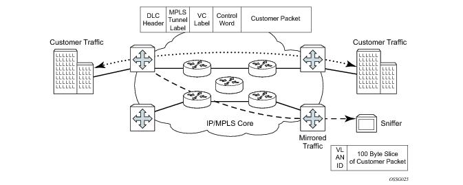
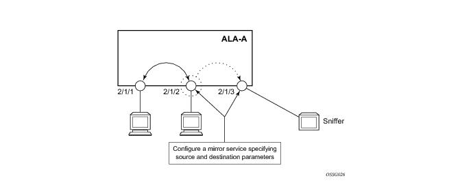
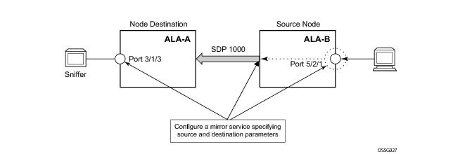
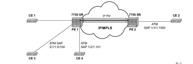
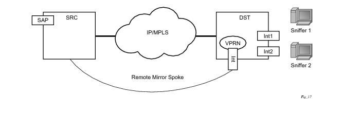
The sniffer is physically connected to this port (3/1/3). SAP, encapsulation requirements, packet slicing, and mirror classification parameters are configured in the destination parameters.
Figure 3: Remote Mirroring Example
 
ATM Mirroring
ATM mirror functionality allows 7750 SR-Series users to mirror AAL5 packets from a source ATM SAP to a destination ATM SAP connected locally or remotely. This functionality can be used to monitor the ATM traffic on a particular ATM SAP. In both the local and remote scenarios the source and destination SAPs must be of ATM SAP type.
All ingress and egress AAL5 traffic at the source ATM SAP is duplicated and sent toward the destination ATM SAP. Mirroring the ingress traffic only, egress traffic only, or both, can be configured. ATM OAM traffic is not mirrored toward the destination ATM SAP.
IP filters used as a mirror source are supported on ATM SAPs based on the IP filter applicability for different services.
ATM mirroring is applicable to the following services using an ATM SAP:
ATM mirroring on an ATM SAP extends the service mirroring feature to include mirror sources with SAP type of ATM. Mirroring is supported on the following services:
Characteristics include:
Mirror destinations for ATM mirroring must be ATM SAPs and cannot be part of an APS group, an IMA bundle, or an IMA Bundle Protection Group (BPGRP).
 
Figure 4: Example of an ATM Mirror Service
In Figure 4, CE 3 is connected to PE1 on ATM SAP 2/1/1/:0/100 as part of an IES service. The traffic on ATM SAP 2/1/1/:0/100 is mirrored locally to CE4 device through ATM SAP 1/2/1:1/101. In this scenario, all AAL5 packets arriving at SAP 2/1/1/:0/100 are duplicated and send towards ATM SAP 1/2/1:1/101.
In the case where the destination ATM SAP is on a remote node PE2, then the AAL5 traffic arriving at ATM SAP 2/1/1/:0/100 is duplicated and sent across the IP/MPLS network to PE2. At PE2 the traffic is forwarded to ATM SAP 1/1/1:0/1000 towards the ATM traffic monitoring device.
 
IP Mirroring
The IP mirroring capability allows a mirror to be created with a parameter that specifies that only the IP packet is mirrored without the original ATM/FR/POS/Ethernet DLC header. This results in the mirrored IP packet becoming media agnostic on the mirror service egress.
This option is configurable on SAP mirrors for IES, VPRN and VPLS services, Ipipe services, and subscriber mirrors. It is not supported on VLL services such as Apipe, Epipe, Fpipe, and on ports.
 
Remote IP Mirroring
Figure 5: Remote IP Mirroring
With remote IP mirroring, the mirror destination configuration can allow IP packets to be mirrored from a source router (Figure 5). The packets will be delivered to the destination in a spoke-terminated interface created in a VPRN service. IES interfaces are not supported. The interface can be configured with policy-based routing filters to allow sniffer selection based on incoming mirrored destination IP addresses. The interface cannot send traffic out as it is a destination only feature. Packets arriving at the interface will be routed based on the routing information within the VPRN. Policy-based routing should always be used unless only a sniffer is connected to the VPRN.
 
Local IP Mirroring
Local mirroring is similar to remote mirroring but the source and destination of the mirror exist in the same Local IP mirroring node. The configuration must include the source address and destination MAC addresses for the packets going to the sniffer. The destination SAP must be Ethernet.
 
Port-ID Enabled PPP Mirroring
Operators that use mirroring for statistics collection make use of VLANs or DLCIs for customer separation. Since PPP offers no such separation, the maximum number of PPP circuits may be identified (one per destination). This feature provides a proprietary mechanism to allow a single mirror to be used.
Port-ID enabled PPP mirroring includes the system’s port ID in the mirrored packet. An operator using this flag in a PPP mirror will be able to identify the end customer circuit by finding the system’s port ID (which is optionally made persistent) and correlating it to the port-id in the mirrored packet.
This mirroring does not change the priority of the mirror order (port/sap/sub/filter). Lawful intercept mirrors can use the flag and their priority is also maintained.
Since the inclusion of the port ID flag is placed on the mirror destination, all mirrored packets of all sources will include the port ID. For remote mirroring, the mirror destination service at the source node must be configured with this flag.
Note the following restrictions:
Subscriber Mirroring
This section describes mirroring based on a subscriber match. Enhanced subscriber management provides the mechanism to associate subscriber hosts with queuing and filtering resources in a shared SAP environment. Mirroring used in subscriber aggregation networks for lawful intercept and debugging is required. With this feature, the mirroring capability allows the match criteria to include a subscriber-id.
Subscriber mirroring provides the ability to create a mirror source with subscriber information as match criteria. Specific subscriber packets can be mirrored mirror when using ESM with a shared SAP without prior knowledge of their IP or MAC addresses and without concern that they may change. The subscriber mirroring decision is more specific than a SAP. If a SAP (or port) is placed in a mirror and a subscriber host of which a mirror was configured is mirrored on that SAP packets matching the subscriber host will be mirrored to the subscriber mirror destination.
The mirroring configuration can be limited to specific forwarding classes used by the subscriber. When a forwarding class (FC) map is placed on the mirror only packets that match the specified FCs are mirrored. A subscriber can be referenced in maximum 2 different mirror-destinations: 1 for ingress and 1 for egress.
Subscriber based criteria in a mirror source remains in the mirror/li source configuration even if the subscriber is deleted, removed or logs off. When the subscriber returns (is configured/created or logs in) the mirroring will resume. This also implies that a subscriber can be configured as a mirror/li source before the actual subscriber exists on the node and before the subscriber id is active (the mirroring will start once the subscriber is actually created or logs in and the subscriber id becomes active).
Lawful Intercept
Lawful Intercept (LI) describes a process to intercept telecommunications by which law enforcement authorities can un-obtrusively monitor voice and data communications to combat crime and terrorism with higher security standards of lawful intercept capabilities in accordance with local law and after following due process and receiving proper authorization from competent authorities. The interception capabilities are sought by various telecommunications providers.
As lawful interception is subject to national regulation, requirements vary from one country to another. ­Alcatel-Lucent’s implementation satisfies most national standard’s requirements. LI capability is configurable for all Alcatel-Lucent service types.
LI mirroring is configured by an operator that has LI permission. LI mirroring is hidden from anyone who does not have the right permission.
 
 
LI Activation Through RADIUS
In additional to CLI and SNMP control, RADIUS messages also activate LI sessions for subscriber-host targets. Activation through RADIUS is equivalent to adding or removing a set of subscriber-host entries in an li-source.
The activation of an LI session via RADIUS can occur in one of two ways:
The following set of VSAs are used to activate LI sessions via RADIUS:
The ALC-LI-FC-MAP VSA can be present several times if more than one forwarding class (FC) is subject to LI.
ALC-LI-Direction and ALC-LI-FC are optional. If either is not included, both directions (ingress and egress) as well as all FCs will be mirrored.
Including the above VSAs in access-accept message will activate LI for newly created host. Note that in this case, the LI activation is not addressed by acct-session-id as this is not yet known during session authorization.
If RADIUS activation is used in a Wholesale/Retail model then the Alc-Retail-Serv-Id VSA must be included in the CoA.
The ability to delete all li-source entries from a particular mirror service is also available via RADIUS. This function may be useful when an LI Mediation device loses sync with the state of the SR-OS node and needs to reset a mirror service to a known state with no LI sessions. This clear function is performed by sending the following attributes in a RADIUS CoA. If the CoA does not contain exactly these three VSAs (each with a valid value matching the configuration on the SR OS router) then the CoA will be silently dropped with no NAK:
ALC-Authentication-Policy-Name (the authentication policy name used to authenticate the subscribers)
The LI-related VSA cannot be combined in one CoA message with other action-related VSAs (force-renew, change of sla-profile, etc.). The only exception to this rule is for the CoA used to create new sub-host. Then, LI-related VSAs can be included along with other VSAs.
If LI is activated through CLI/SNMP, the activation through RADIUS takes precedence. The precedence in this context means that RADIUS activation of LI will fully override whatever was configured at CLI/SNMP level for this particular host. If the RADIUS LI is de-activated, the CLI/SNMP configuration will become active again.
The LI-related VSAs are not shown in debug messages. The show li li-source <xxxx> command shows all sub-hosts for which LI was activated using RADIUS VSAs. This command is only accessible to CLI users with LI privileges.
 
 
Routable Lawful Intercept Encapsulation
The Routable LI encapsulation feature allows LI mirrored packets to be placed into a routable (for example, IP/UDP) header and then forwarded in a routing context (base or vprn). An LI-shim inserted before the customer packet allows correlation of packets to LI sessions at the downstream LI Mediation device (LIG).
Figure 6: Routable Lawful Intercept Encapsulation
Figure 7: Routable Encapsulation Format
Some of the supported attributes and scenarios for the routable LI encapsulation feature include the following:
Figure 8: LI-Shim version 01 with a direction bit
User configurable intercept-id and session-id per li-source entry that is placed into the li-shim (a total max of 62 configurable bits).
ip|udp|li-shim encap is available for ether and ip-only mirror-dest types (note that ip-only supports, amongst other formats, packets that are reassembled from ATM cells.)
Fragmentation of the resulting mirror packet is supported. Note that fragmentation is supported for NAT LI with the Routable Encapsulation, but fragmentation is not supported for NAT LI with ethernet-encap.
The following restrictions apply to the routable LI encapsulation feature:
Only applicable to Lawful Intercept and is not available for debug or MS-ISA based Application Assurance mirrors.
Care must be taken in the configuration of LI mirrors and the destination IP address for the routable LI encapsulation. Incorrect selection of the destination IP could send packets to unintended destinations (for example - configuring the encapsulation with a subscriber's IP address), and combinations of mirrors and routable encapsulation can create loops in the network.
Pseudowire Redundant Mirror Services
This section describes the implementation and configuration of redundant Mirror/Lawful Intercept services using redundant pseudowires.
Regardless of the protection mechanism (MC-LAG, STP or APS) the source switch will only transmit on the active link and not simultaneously on the standby link. As a result when configuring a redundant mirror / LI service or a mirror service where the customer has a redundant service but the mirror / LI service is not redundant the mirror source must be configured on both (A and B) PE nodes. In either case the PE with a mirror source will establish a pseudo wire to each eligible PE where the mirror / LI service terminates.
Figure 9: State Engine for Redundant Service to a Redundant Mirror Service
It is important to note that in order to provide protection in case the active SDP between node A and D fails and the need to limit the number of lost data for LI the ICB between node A and B must be supported. As a result when the SDP connecting nodes A and D fails the data on its way from the source switch to node A and the data in node A must be directed by the ICB to node B and from there to node D.
This functionality is already supported in when providing pseudo wire redundancy for VLLs and must be extended to mirror / LI service redundancy.
Figure 10: State Engine for Redundant Service to a Non-Redundant Mirror Service
The notable difference with scenarios standard pseudo wire redundancy scenarios is that provided the customer service is redundant on nodes A and B (Figure 9 and Figure 10) both aggregation node A and Aggregation node B maintain an active Pseudo wire to Node D who in turn has an active link to the destination switch. If in the sample in Figure 9, the link between D and the destination switch is disconnected then both aggregation A and B must switch to use pseudo wire connection to Node C.
Figure 11: State Engine for a Non-Redundant Service to a Redundant Mirror Service
In the case where a non redundant service is being mirrored to a redundant mirror service (Figure 11) the source aggregation node (A) can only maintain a pseudo wire to the active destination aggregation node (D). Should the link between aggregation node D and the destination switch fail then the pseudo wire must switch to the new active aggregation node (C).
 
Redundant Mirror Source Notes
A redundant remote mirror service destination is not supported for IP Mirrors (a set of remote IP mirror destinations). The remote destination of an IP mirror is a VPRN instance, and an “endpoint” cannot be configured in a VPRN service.
A redundant mirror source is supported for IP mirrors, but the remote destination must be a single node (a set of mirror source nodes, each with a mirror destination that points to the same destination node). In this case the destination node would have a VPRN instance with multiple ip-mirror-interfaces.
Multi Chassis APS (MC-APS) groups can not be used as the SAP for a redundant remote mirror destination service. APS can not be used to connect the remote mirror destination SR nodes to a destination switch.
Multi Chassis APS (MC-APS) groups can be used as the SAP for a redundant mirror service source. APS can be used to redundantly connect the source of the mirrored traffic to the SR nodes that are behaving as the mirror-sources.
 
Carrier Grade NAT – Lawful Intercept
Lawful intercept for NAT is supported to mirror configured subscriber’s traffic to a mirror-destination. When active, packets are mirrored from the perspective of the NAT outside interface (thus after NAT translations have occurred). All traffic for the specified subscriber, including traffic associated with static port-forwards, is mirrored.
A simplified Ethernet encapsulation (with an optional Intercept ID) is used for all NAT traffic. When mirroring NAT traffic, the mirror-destination must be of type ether. The customer packet from the (outside) IP Header onwards (including the IP header) is mirrored. The operator has the configuration option of embedding the Intercept ID into the LI packet through the use of an explicit intercept-id command. Both packet formats are described below:
 
Figure 12: Ethernet Mirror Examples
 
The contents of the highlighted fields is configurable using the following CLI:
	li
li-source service-id
nat
classic-lsn-sub router name ip address
intercept-id id
dslite-lsn-sub router name b4 ipv6-address
intercept-id id
l2-aware-sub sub-ident
intercept-id id
 
The default ethernet-header is to use etype 0x600 and system MAC address for both source and destination address. The configurable Ethertype and Intercept ID is only added when an intercept-id is present for the subscriber in the NAT config.
 
Configuration Process Overview
Figure 13 displays the process to provision basic mirroring parameters.
Figure 13: Mirror Configuration and Implementation Flow
 
Figure 14 displays the process to provision LI parameters.
Figure 14: Lawful Intercept Configuration and Implementation Flow
Configuration Notes
This section describes mirroring configuration caveats.
Mirror and lawful intercept source criteria configuration (defined in debug>mirror>mirror-source and config>li>li-source) is not preserved in a configuration save (admin save). Debug mirror source configuration can be saved using admin>debug-save. Lawful intercept source configuration can be saved using config>li>save.
Mirror destinations:
When a mirror destination service ID is shutdown, mirrored packets associated with the service ID are not accepted from its mirror source or remote source. The associated mirror source is put into an operationally down mode. Mirrored packets are not transmitted out the SAP or SDP. Each mirrored packet is silently discarded. If the mirror destination is a SAP, the SAP’s discard counters are incremented.
Issuing the shutdown command causes the mirror destination service or its mirror source to be put into an administratively down state. Mirror destination service IDs must be shut down first in order to delete a service ID, or SAP, or SDP association from the system.
Mirror sources:
The default state for a mirror source for a given mirror-dest service ID is no shutdown. Enter a shutdown command to deactivate (disable) mirroring from that mirror-source.
The following are lawful intercept configuration caveats.
Network management — Operators without LI permission cannot view or manage the LI data on the node nor can they view or manage the data on the Network Management platform.
LI mirroring does not allow the configuration of ports and ingress labels as a source parameter.