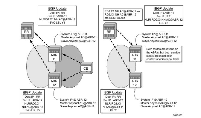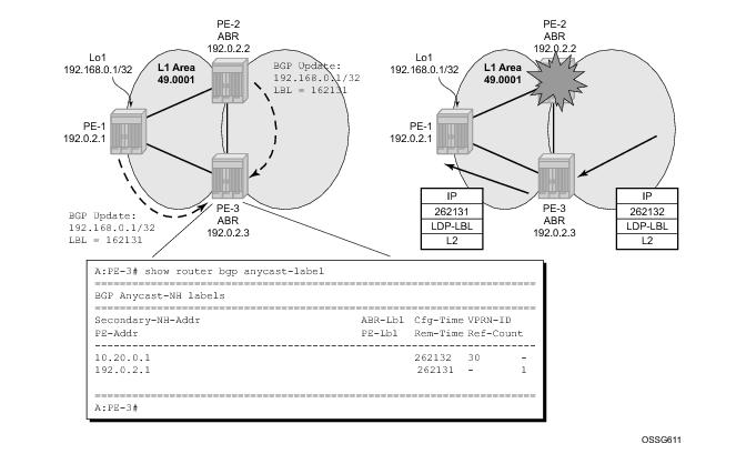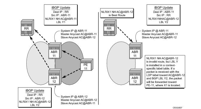
Note that Figure 130 shows that X1 will be advertised by both (redundant) ABRs, each assigning their master anycast address as the NH. RR will select one of them as best and will reflect the route towards both ABRs. Only one ABR (ABR-11 in this case) will install the BGP anycast route towards the destination X1. This is fine since ABR-12 will be selected by the other ABR (connected to remote regions) in the core as NH for the route towards X1/32, hence ABR-12 will receive the traffic from other regions towards X1, and if there is a failure on ABR-12 (link/nodal) traffic will be diverted to ABR-11. ABR-11 can interpret the LDP and BGP labels, which are advertised by ILDP and the BGP label (in the context-specific label space), which results in forwarding traffic to X1.
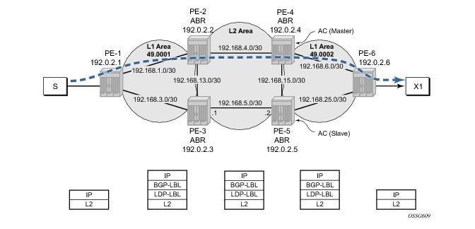
Figure 132 illustrates the data path from source S to destination X1.
A:PE-2>config>router# info
----------------------------------------------
#--------------------------------------------------
echo "IP Configuration"
#--------------------------------------------------
mh-primary-interface "masterAnycast"
address 10.20.0.1/32
exit
mh-secondary-interface "slaveAnycast"
address 10.30.0.1/32
*A:PE-3>config>router# info
----------------------------------------------
#--------------------------------------------------
echo "IP Configuration"
#--------------------------------------------------
mh-primary-interface "masterAnycast"
address 10.30.0.1/32
exit
mh-secondary-interface "slaveAnycast"
address 10.20.0.1/32
exit
*A:PE-3>config>router# show router interface "masterAnycast" detail | match Port
Port Id : vport-7
*A:PE-3>config>router#
*A:PE-2>config>router# show router route-table
===============================================================================
Route Table (Router: Base)
===============================================================================
Dest Prefix Type Proto Age Pref
Next Hop[Interface Name] Metric
-------------------------------------------------------------------------------
10.20.0.1/32 Local Local 01d14h16m 0
masterAnycast 0
10.30.0.1/32 Local Local 01d14h16m 0
slaveAnycast 0
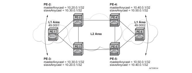
	PE-4:	masterAnycast 	= 	10.40.0.1/32
		slaveAnycast 	= 	10.50.0.1/32
	PE-5: 	masterAnycast 	= 	10.50.0.1/32
		slaveAnycast 	= 	10.40.0.1/32
*A:PE-2>config>router>isis# info
----------------------------------------------
area-id 49.0001
export "remoteABR"
traffic-engineering
interface "system"
passive
exit
interface "masterAnycast"
level-capability level-2
exit
interface "slaveAnycast"
level-capability level-2
exit
interface "int-PE-2-PE-3"
level-capability level-2
interface-type point-to-point
exit
interface "int-PE-2-PE-4"
level-capability level-2
interface-type point-to-point
exit
interface "int-PE-2-PE-1"
level-capability level-1
interface-type point-to-point
exit
----------------------------------------------
*A:PE-2>config>router>isis#
*A:PE-2>config>router>isis# show router isis interface
===============================================================================
ISIS Interfaces
===============================================================================
Interface Level CircID Oper State L1/L2 Metric
-------------------------------------------------------------------------------
system L1L2 1 Up 0/0
masterAnycast L2 2 Up -/10
slaveAnycast L2 3 Up -/30
*A:PE-2>config>router>policy-options# info
----------------------------------------------
prefix-list "PE"
prefix 192.0.2.1/32 exact
exit
prefix-list "remoteABR"
prefix 10.40.0.1/32 exact
prefix 10.50.0.1/32 exact
prefix 192.0.2.4/32 exact
prefix 192.0.2.5/32 exact
exit
prefix-list "masterAnycast"
prefix 10.20.0.1/32 exact
exit
policy-statement "remoteABR"
entry 10
from
prefix-list "remoteABR"
exit
action accept
exit
exit
entry 20
description "reject system-ip of own region"
from
prefix-list "PE"
exit
action reject
exit
exit
*A:PE-2>config>router>ldp# info
----------------------------------------------
export "exp-anycast"
interface-parameters
interface "int-PE-2-PE-3"
exit
interface "int-PE-2-PE-4"
exit
interface "int-PE-2-PE-1"
exit
exit
targeted-session
exit
----------------------------------------------
* A:PE-2>config>router>ldp# show router policy "exp-anycast"
entry 10
description "advertise master anycast address"
from
prefix-list "masterAnycast"
exit
to
protocol ldp
exit
action accept
exit
exit
entry 20
description "advertise slave anycast address as well"
from
prefix-list "slaveAnycast"
exit
to
protocol ldp
exit
action accept
exit
exit
A:PE-2>config>router>ldp#
A:PE-2>config>router>ldp# show router ldp bindings
===============================================================================
LDP LSR ID: 192.0.2.2
===============================================================================
Legend: U - Label In Use, N - Label Not In Use, W - Label Withdrawn
S - Status Signaled Up, D - Status Signaled Down
E - Epipe Service, V - VPLS Service, M - Mirror Service
A - Apipe Service, F - Fpipe Service, I - IES Service, R - VPRN service
P - Ipipe Service, WP - Label Withdraw Pending, C - Cpipe Service
TLV - (Type, Length: Value)
===============================================================================
LDP Prefix Bindings
===============================================================================
Prefix Peer IngLbl EgrLbl EgrIntf/ EgrNextHop
LspId
-------------------------------------------------------------------------------
10.20.0.1/32 192.0.2.1 262140U -- -- --
10.20.0.1/32 192.0.2.4 262140U -- -- --
10.30.0.1/32 192.0.2.1 262139U -- -- --
10.30.0.1/32 192.0.2.4 262139U -- -- --
10.40.0.1/32 192.0.2.1 262143U 262143 -- --
10.40.0.1/32 192.0.2.3 262143U 262135 -- --
10.40.0.1/32 192.0.2.4 -- 262139 1/1/3:0 192.168.4.2
10.50.0.1/32 192.0.2.1 262130U 262138 -- --
10.50.0.1/32 192.0.2.3 262130N 262142 1/1/2:0 192.168.13.2
10.50.0.1/32 192.0.2.4 -- 262143 -- --
192.0.2.1/32 192.0.2.1 -- 262142 1/1/1:0 192.168.2.1
192.0.2.1/32 192.0.2.3 262134U 262132 -- --
*A:PE-2# oam lsp-trace prefix 10.40.0.1/32
lsp-trace to 10.40.0.1/32: 0 hops min, 0 hops max, 104 byte packets
1 192.0.2.4 rtt=2.02ms rc=3(EgressRtr)
*A:PE-2# oam lsp-trace prefix 10.50.0.1/32
lsp-trace to 10.50.0.1/32: 0 hops min, 0 hops max, 104 byte packets
1 192.0.2.3 rtt=2.76ms rc=8(DSRtrMatchLabel)
2 192.0.2.5 rtt=3.57ms rc=3(EgressRtr)
*A:PE-2#
*A:PE-2# configure router bgp
*A:PE-2>config>router>bgp# info
----------------------------------------------
min-route-advertisement 10
group "region"
description "all PE of the region will peer with this ABR"
family ipv4 vpn-ipv4
type internal
cluster 2.2.2.2
neighbor 192.0.2.1
advertise-label ipv4
exit
exit
group "fullmesh"
description "PE-4 is RR"
family ipv4 vpn-ipv4
type internal
export "exp-anycast-nhs"
neighbor 192.0.2.4
advertise-label ipv4
exit
exit
----------------------------------------------
*A:PE-2>config>router>bgp#
A:PE-2>config>router>bgp# show router policy "exp-anycast-nhs"
entry 10
description "set NH of PE to master anycast"
from
prefix-list "PE"
family ipv4
exit
to
protocol bgp
exit
action accept
local-preference 150 (*)
next-hop 10.20.0.1
exit
exit
entry 20
description "set NH of IP-VPN routes to master anycast"
from
family vpn-ipv4
exit
to
protocol bgp-vpn
exit
action accept
local-preference 150 (*)
next-hop 10.20.0.1
exit
exit
A:PE-2>config>router>bgp#
A:PE-4>config>router>bgp# info
----------------------------------------------
vpn-apply-import
vpn-apply-export
min-route-advertisement 1
group "region"
description "all PE of the region will peer with this ABR"
family ipv4 vpn-ipv4
type internal
cluster 4.4.4.4
neighbor 192.0.2.6
advertise-label ipv4
exit
exit
group "fullmesh"
description "RR in cluster 1.1.1.1"
family ipv4 vpn-ipv4
type internal
cluster 1.1.1.1
export "exp-anycast-nhs"
neighbor 192.0.2.2
advertise-label ipv4
exit
neighbor 192.0.2.3
advertise-label ipv4
exit
neighbor 192.0.2.5
advertise-label ipv4
exit
exit
----------------------------------------------
A:PE-4>config>router>bgp# show router policy "exp-anycast-nhs"
entry 10
description "set NH of PE to master anycast"
from
prefix-list "PE"
family ipv4
exit
to
protocol bgp
exit
action accept
local-preference 150
next-hop 10.40.0.1
exit
exit
A:PE-4# show router policy prefix-list "PE"
prefix 192.0.2.6/32 exact
prefix 192.168.0.6/32 exact
A:PE-4#
*A:PE-1# configure router bgp
*A:PE-1>config>router>bgp# info
----------------------------------------------
min-route-advertisement 10
group "abr"
description "peering to ABR, which act as RR"
family ipv4 vpn-ipv4
type internal
export "expbgp"
neighbor 192.0.2.2
advertise-label ipv4
exit
neighbor 192.0.2.3
advertise-label ipv4
exit
exit
----------------------------------------------
A:PE-1>config>router>bgp#
A:PE-1# show router policy "expbgp"
entry 10
from
prefix-list "PE"
exit
to
protocol bgp
exit
action accept
exit
exit
A:PE-1# show router policy prefix-list "PE"
prefix 192.0.2.1/32 exact
A:PE-1#
A:PE-1# show router bgp routes 192.0.2.6/32
===============================================================================
BGP Router ID:192.0.2.1 AS:65536 Local AS:65536
===============================================================================
Legend -
Status codes : u - used, s - suppressed, h - history, d - decayed, * - valid
Origin codes : i - IGP, e - EGP, ? - incomplete, > - best
===============================================================================
BGP IPv4 Routes
===============================================================================
Flag Network LocalPref MED
Nexthop VPNLabel
As-Path
-------------------------------------------------------------------------------
u*>i 192.0.2.6/32 150 10
10.40.0.1 -
No As-Path
*i 192.0.2.6/32 150 10
10.50.0.1 -
No As-Path
-------------------------------------------------------------------------------
Routes : 2
===============================================================================
A:PE-1#
*A:PE-1# show router ldp bindings prefix 10.40.0.1/32
===============================================================================
LDP LSR ID: 192.0.2.1
===============================================================================
Legend: U - Label In Use, N - Label Not In Use, W - Label Withdrawn
WP - Label Withdraw Pending
===============================================================================
LDP Prefix Bindings
===============================================================================
Prefix Peer IngLbl EgrLbl EgrIntf EgrNextHop
-------------------------------------------------------------------------------
10.40.0.1/32 192.0.2.2 262143N 262143 1/1/1:0 192.168.2.2
10.40.0.1/32 192.0.2.3 262143U 262135 -- --
-------------------------------------------------------------------------------
No. of Prefix Bindings: 2
===============================================================================
*A:PE-1# oam lsp-trace prefix 10.40.0.1/32
lsp-trace to 10.40.0.1/32: 0 hops min, 0 hops max, 104 byte packets
1 192.0.2.2 rtt=2.18ms rc=8(DSRtrMatchLabel)
2 192.0.2.4 rtt=2.88ms rc=3(EgressRtr)
*A:PE-1#
A:PE-2# show router bgp anycast-label
===============================================================================
BGP Anycast-MH labels
===============================================================================
Secondary-MH-Addr ABR-Lbl Cfg-Time VPRN-ID
PE-Addr PE-Lbl Rem-Time Ref-Count
-------------------------------------------------------------------------------
10.30.0.1 262130 30 1
- - - 3
===============================================================================
A:PE-2#
A:PE-3# show router bgp anycast-label
===============================================================================
BGP Anycast-MH labels
===============================================================================
Secondary-MH-Addr ABR-Lbl Cfg-Time VPRN-ID
PE-Addr PE-Lbl Rem-Time Ref-Count
-------------------------------------------------------------------------------
10.20.0.1 262131 30 -
192.0.2.1 262134 - 1
10.20.0.1 262133 30 1
- - - 3
===============================================================================
A:PE-3#
*A:PE-1# show router route-table 192.0.2.6/32
===============================================================================
Route Table (Router: Base)
===============================================================================
Dest Prefix Type Proto Age Pref
Next Hop[Interface Name] Metric
-------------------------------------------------------------------------------
192.0.2.6/32 Remote BGP 00h30m50s 170
10.40.0.1 (tunneled) 0
-------------------------------------------------------------------------------
No. of Routes: 1
===============================================================================
*A:PE-1#
*A:PE-1# show router fib 1 192.0.2.6/32
===============================================================================
FIB Display
===============================================================================
Prefix Protocol
NextHop
-------------------------------------------------------------------------------
192.0.2.6/32 BGP
10.40.0.1 (Transport:LDP)
-------------------------------------------------------------------------------
Total Entries : 1
-------------------------------------------------------------------------------
===============================================================================
...
*A:PE-1# show router tunnel-table
===============================================================================
Tunnel Table (Router: Base)
===============================================================================
Destination Owner Encap TunnelId Pref Nexthop Metric
-------------------------------------------------------------------------------
192.0.2.6/32 bgp MPLS - 10 10.40.0.1 1000
===============================================================================
*A:PE-1# traceroute 192.0.2.6 no-dns
traceroute to 192.0.2.6, 30 hops max, 40 byte packets
1 192.0.2.6 28.9 ms 4.53 ms 5.00 ms
*A:PE-1#
*A:PE-1>config>router# info
----------------------------------------------
#--------------------------------------------------
echo "IP Configuration"
#--------------------------------------------------
interface "lo1"
address 192.168.0.1/32
description "simulate an AN (access node) "
loopback
exit
interface "system"
address 192.0.2.1/32
exit
autonomous-system 64496
A:PE-1# configure router bgp
A:PE-1>config>router>bgp# info
----------------------------------------------
vpn-apply-import
vpn-apply-export
min-route-advertisement 1
group "abr"
description "peering to ABR, which act as RR"
family ipv4 vpn-ipv4
type internal
export "expbgp"
neighbor 192.0.2.2
advertise-label ipv4
exit
neighbor 192.0.2.3
advertise-label ipv4
exit
exit
----------------------------------------------
A:PE-1>config>router>bgp# show router policy "expbgp"
entry 10
description "advertise the PE system-ip through BGP"
from
prefix-list "PE"
exit
to
protocol bgp
exit
action accept
local-preference 200
exit
exit
entry 20
description "advertise connect AN through BGP"
from
prefix-list "AN"
exit
to
protocol bgp
exit
action accept
exit
exit
A:PE-1>config>router>bgp# show router policy prefix-list "AN"
prefix 192.168.0.1/32 exact
A:PE-1>config>router>bgp# show router policy prefix-list "PE"
prefix 192.0.2.1/32 exact
A:PE-1>config>router>bgp#
BGP anycast for A:PE-3# show router bgp anycast-label
===============================================================================
BGP Anycast-MH labels
===============================================================================
Secondary-MH-Addr ABR-Lbl Cfg-Time VPRN-ID
PE-Addr PE-Lbl Rem-Time Ref-Count
-------------------------------------------------------------------------------
10.20.0.1 262131 30 -
192.0.2.1 262134 - 1
10.20.0.1 262132 30 -
192.0.2.1 262131 - 1
Important note: If an E2E MPLS transport tunnel is needed between PE-1 and PE-6, additional loopback interfaces need to be created on both PE since the system address cannot be used with the BGP anycast feature. The reason for this is that on the ABR, the best route towards the PE system-ip is an IGP route, not a (labeled) BGP route. BGP anycast can only map a BGP label against another BGP label, not towards an IGP (hence LDP) route
1. This is important to keep in mind, if BGP anycast is deployed in networks where BGP anycast is required for E2E MPLS tunnels between AN and remote PEs.
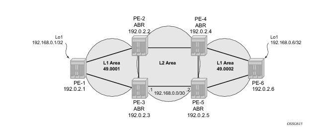
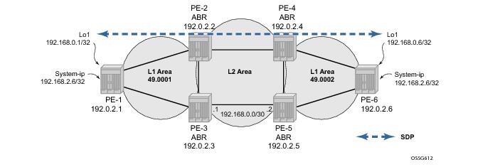
Figure 137 illustrates the SDP between PE-1 and PE-6.
*A:PE-1# configure service sdp 100
*A:PE-1>config>service>sdp# info
----------------------------------------------
far-end 192.168.0.6
bgp-tunnel
keep-alive
shutdown
exit
no shutdown
----------------------------------------------
*A:PE-1>config>service>sdp#
*A:PE-1# show router interface "lo1"
===============================================================================
Interface Table (Router: Base)
===============================================================================
Interface-Name Adm Opr(v4/v6) Mode Port/SapId
IP-Address PfxState
-------------------------------------------------------------------------------
lo1 Up Up/Down Network loopback
192.168.0.1/32 n/a
-------------------------------------------------------------------------------
Interfaces : 1
===============================================================================
*A:PE-1#
*A:PE-1# configure router ldp
*A:PE-1>config>router>ldp# info
----------------------------------------------
interface-parameters
interface "int-PE-1-PE-2"
exit
interface "int-PE-1-PE-3"
exit
exit
targeted-session
peer 192.168.0.6
local-lsr-id "lo1"
exit
exit
----------------------------------------------
*A:PE-1>config>router>ldp#
Important note: In the SR-OS 9.0R1 software release, BGP anycast for IP-VPN routes is only supported with a RR cluster in the core. A full mesh of iBGP peers or confederations are not supported in SROS 9.0R1.
The BGP anycast mechanism can also be used to advertise IP-VPN routes. The advertising PE sets the NH equal to the anycast master address instead of the regular system IP. The configuration is based upon PE-1 which will now act as a customer edge (CE) device. This can be achieved by creating a local IP-VPN on PE-1, without any MPLS connectivity, due to the use of a unique RT (route-target) and hybrid ports towards the ABR
2. As such, both PE-2 and PE-3 can advertise the same route with the AC address as a NH.
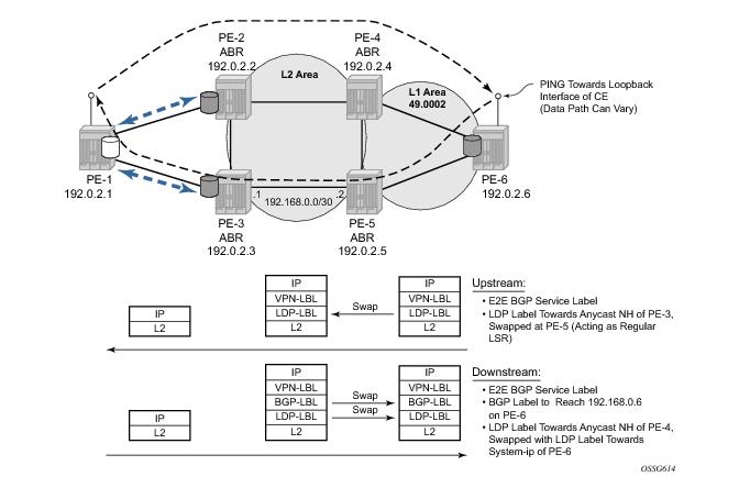
Figure 138 illustrates the logical IP-VPN topology.
A:PE-2>config>service>vprn# info
----------------------------------------------
description "IP-VPN PE, with anycast NH set"
vrf-import "vrfImpPolBgpVpnRts"
vrf-export "adv_vpn"
router-id 192.0.2.2
autonomous-system 64498
route-distinguisher 1:2
auto-bind ldp
vrf-target target:1:1
interface "to_CE" create
address 172.16.2.2/30
sap 1/1/1:1 create
exit
exit
bgp
group "CE"
type external
export "exp_bgp_vpn_rts_to_ce"
peer-as 64499
neighbor 172.16.2.1
exit
exit
exit
no shutdown
----------------------------------------------
A:PE-2>config>service>vprn#
A:PE-2>config>service>vprn# show router policy "vrfImpPolBgpVpnRts"
description "Policy From bgpVpn To none"
entry 10
description "Entry 10 - From Prot. bgpVpn To none"
from
protocol bgp-vpn
community "vprn1"
exit
to
exit
action accept
exit
exit
A:PE-2>config>service>vprn# show router policy "adv_vpn"
entry 10
description "local routes"
from
protocol direct
exit
to
protocol bgp-vpn
exit
action accept
community add "vprn1"
exit
exit
entry 20
description "PE-CE BGP routes"
from
protocol bgp
exit
to
protocol bgp-vpn
exit
action accept
community add "vprn1"
exit
exit
A:PE-2# show router policy community "vprn1"
community "vprn1" members "target:1:1"
A:PE-2#
A:PE-2# show router policy "exp_bgp_vpn_rts_to_ce"
description "Policy From bgpVpn To none"
entry 10
description "Entry 10 - From Prot. bgpVpn To none"
from
protocol bgp-vpn
exit
to
exit
action accept
exit
exit
A:PE-2#
*A:PE-2# configure router bgp
*A:PE-2>config>router>bgp# info
----------------------------------------------
vpn-apply-export
min-route-advertisement 1
group "region"
description "all PE of the region will peer with this ABR"
family ipv4 vpn-ipv4
type internal
cluster 1.1.1.1
neighbor 192.0.2.1
advertise-label ipv4
exit
exit
group "fullmesh"
description "PE-4 is RR"
family ipv4 vpn-ipv4
type internal
export "exp-anycast-nhs"
neighbor 192.0.2.4
advertise-label ipv4
exit
exit
----------------------------------------------
*A:PE-2>config>router>bgp# show router policy "exp-anycast-nhs"
entry 10
description "set NH of PE to master anycast"
from
prefix-list "PE"
family ipv4
exit
to
protocol bgp
exit
action accept
local-preference 150 (*)
next-hop 10.20.0.1
exit
exit
entry 20
description "set NH of IP-VPN routes to master anycast"
from
family vpn-ipv4
exit
to
protocol bgp-vpn
exit
action accept
local-preference 150 (*)
next-hop 10.20.0.1
exit
exit
*A:PE-2>config>router>bgp#
(*) optional
A:PE-6>config>service>vprn# info
----------------------------------------------
vrf-import "vrfImpPolBgpVpnRts"
router-id 172.16.6.6
route-distinguisher 1:6
auto-bind mpls
vrf-target target:1:1
interface "lo1" create
address 172.16.6.6/32
loopback
exit
no shutdown
----------------------------------------------
A:PE-6>config>service>vprn#
A:PE-6# configure router bgp
A:PE-6>config>router>bgp# info
----------------------------------------------
vpn-apply-import
vpn-apply-export
min-route-advertisement 1
outbound-route-filtering
exit
group "abr"
description "peering to ABR, which act as RR"
family ipv4 vpn-ipv4
type internal
export "expbgp"
neighbor 192.0.2.4
advertise-label ipv4
exit
neighbor 192.0.2.5
advertise-label ipv4
exit
exit
----------------------------------------------
A:PE-6>config>router>bgp# show router policy
policy policy-edits
A:PE-6>config>router>bgp# show router policy "expbgp"
entry 10
description "advertise the PE system-ip through BGP"
from
prefix-list "PE"
exit
to
protocol bgp
exit
action accept
local-preference 200
exit
exit
entry 20
description "advertise connect AN through BGP"
from
prefix-list "AN"
exit
to
protocol bgp
exit
action accept
exit
exit
entry 30
description "set NH for vpn-routes to 192.168.0.6"
from
community "vprn1"
exit
action accept
local-preference 333
next-hop 192.168.0.6
exit
exit
A:PE-6>config>router>bgp# exit all
A:PE-6# show router policy prefix-list "AN"
prefix 192.168.0.6/32 exact
A:PE-6# show router policy prefix-list "PE"
prefix 192.0.2.6/32 exact
A:PE-6#
A:PE-6# show router interface
===============================================================================
Interface Table (Router: Base)
===============================================================================
Interface-Name Adm Opr(v4/v6) Mode Port/SapId
IP-Address PfxState
-------------------------------------------------------------------------------
int-PE-6-PE-4 Up Up/Down Network 1/1/1:0
192.168.6.2/30 n/a
int-PE-6-PE-5 Up Up/Down Network 1/1/3:0
192.168.25.2/30 n/a
lo1 Up Up/Down Network loopback
192.168.0.6/32 n/a
system Up Up/Down Network system
192.0.2.6/32 n/a
-------------------------------------------------------------------------------
Interfaces : 4
===============================================================================
A:PE-6#
A:PE-2# show router tunnel-table
===============================================================================
Tunnel Table (Router: Base)
===============================================================================
Destination Owner Encap TunnelId Pref Nexthop Metric
-------------------------------------------------------------------------------
10.40.0.1/32 ldp MPLS - 9 192.168.4.2 20
10.50.0.1/32 ldp MPLS - 9 192.168.13.2 30
192.0.2.1/32 ldp MPLS - 9 192.168.2.1 10
192.0.2.3/32 ldp MPLS - 9 192.168.2.1 20
192.0.2.4/32 ldp MPLS - 9 192.168.4.2 10
192.0.2.5/32 ldp MPLS - 9 192.168.13.2 20
192.0.2.6/32 bgp MPLS - 10 10.40.0.1 1000
192.168.0.6/32 bgp MPLS - 10 10.40.0.1 1000
===============================================================================
A:PE-2#
A:PE-4# show router bgp anycast-label
===============================================================================
BGP Anycast-MH labels
===============================================================================
Secondary-MH-Addr ABR-Lbl Cfg-Time VPRN-ID
PE-Addr PE-Lbl Rem-Time Ref-Count
-------------------------------------------------------------------------------
10.50.0.1 262132 30 -
192.0.2.6 262132 - 1
===============================================================================
A:PE-4#
A:PE-1>config>service>vprn# info
----------------------------------------------
description "local VPN, simulating CE"
router-id 172.168.1.1
autonomous-system 64499
route-distinguisher 1:1
interface "to_ABR_PE3" create
address 172.16.3.1/30
sap 1/1/3:1 create
exit
exit
interface "to_ABR_PE2" create
address 172.16.2.1/30
sap 1/1/1:1 create
exit
exit
interface "lo1" create
address 172.168.1.1/32
loopback
exit
bgp
min-route-advertisement 1
export "adv_direct"
group "ABR"
type external
peer-as 64498
neighbor 172.16.2.2
exit
neighbor 172.16.3.2
exit
exit
exit
no shutdown
----------------------------------------------
A:PE-1>config>service>vprn#
A:PE-1>config>service>vprn# show router policy "adv_direct"
entry 10
description "advertise local interfaces to PE"
from
protocol direct
exit
to
protocol bgp
exit
action accept
exit
exit
A:PE-1>config>service>vprn#
A:PE-1# show router 1 bgp summary
===============================================================================
BGP Router ID:192.0.2.1 AS:64499 Local AS:64499
===============================================================================
BGP Admin State : Up BGP Oper State : Up
Total Peer Groups : 1 Total Peers : 2
Total BGP Paths : 3 Total Path Memory : 384
Total IPv4 Remote Rts : 4 Total IPv4 Rem. Active Rts : 0
Total IPv6 Remote Rts : 0 Total IPv6 Rem. Active Rts : 0
Total Supressed Rts : 0 Total Hist. Rts : 0
Total Decay Rts : 0
===============================================================================
BGP Summary
===============================================================================
Neighbor
AS PktRcvd InQ Up/Down State|Rcv/Act/Sent (Addr Family)
PktSent OutQ
-------------------------------------------------------------------------------
172.16.2.2
64498 28695 0 05d23h53m 2/0/3 (IPv4)
28671 0
172.16.3.2
64498 28618 0 06d00h03m 2/0/3 (IPv4)
28611 0
-------------------------------------------------------------------------------
A:PE-1#
A:PE-2# show router bgp routes vpn-ipv4 1:3:172.168.1.1/32
===============================================================================
BGP Router ID:192.0.2.2 AS:64496 Local AS:64496
===============================================================================
Legend -
Status codes : u - used, s - suppressed, h - history, d - decayed, * - valid
Origin codes : i - IGP, e - EGP, ? - incomplete, > - best
===============================================================================
BGP VPN-IPv4 Routes
===============================================================================
Network : 172.168.1.1/32
Nexthop : 10.30.0.1
Route Dist. : 1:3 VPN Label : 262130
From : 192.0.2.4
Res. Nexthop : n/a
Local Pref. : 150 Interface Name : slaveAnycast
Aggregator AS : None Aggregator : None
Atomic Aggr. : Not Atomic MED : None
Community : target:1:1
Cluster : 1.1.1.1
Originator Id : 192.0.2.3 Peer Router Id : 192.0.2.4
Flags : Invalid Incomplete (*)
AS-Path : 64499
VPRN Imported : None
-------------------------------------------------------------------------------
Routes : 1
A:PE-2# show router bgp anycast-label
===============================================================================
BGP Anycast-MH labels
===============================================================================
Secondary-MH-Addr ABR-Lbl Cfg-Time VPRN-ID
PE-Addr PE-Lbl Rem-Time Ref-Count
-------------------------------------------------------------------------------
10.30.0.1 262130 30 1
- - - 3
===============================================================================
A:PE-2#
A:PE-2# show router 1 route-table
===============================================================================
Route Table (Service: 1)
===============================================================================
Dest Prefix Type Proto Age Pref
Next Hop[Interface Name] Metric
-------------------------------------------------------------------------------
172.16.2.0/30 Local Local 06d00h35m 0
to_CE 0
172.16.3.0/30 Remote BGP 05h01m41s 170
172.16.2.1 0
172.168.1.1/32 Remote BGP 06d00h35m 170
172.16.2.1 0
-------------------------------------------------------------------------------
No. of Routes: 3
===============================================================================
A:PE-2#
A:PE-6# ping router 1 172.168.1.1 source 172.16.6.6
PING 172.168.1.1 56 data bytes
64 bytes from 172.168.1.1: icmp_seq=1 ttl=63 time=3.79ms.
^C
ping aborted by user
---- 172.168.1.1 PING Statistics ----
1 packet transmitted, 1 packet received, 0.00% packet loss
round-trip min = 3.79ms, avg = 3.79ms, max = 3.79ms, stddev = 0.000ms
A:PE-6# traceroute no-dns router 1 172.168.1.1 source 172.16.6.6
traceroute to 172.168.1.1 from 172.16.6.6, 30 hops max, 40 byte packets
1 0.0.0.0 * * *
2 172.168.1.1 4.62 ms 8.05 ms 4.28 ms
A:PE-6#
A:PE-6# show router 1 route-table
===============================================================================
Route Table (Service: 1)
===============================================================================
Dest Prefix Type Proto Age Pref
Next Hop[Interface Name] Metric
-------------------------------------------------------------------------------
172.16.2.0/30 Remote BGP VPN 16h21m20s 170
10.20.0.1 (tunneled) 0
172.16.3.0/30 Remote BGP VPN 16h21m20s 170
10.30.0.1 (tunneled) 0
172.16.6.6/32 Local Local 10d21h52m 0
lo1 0
172.168.1.1/32 Remote BGP VPN 16h21m20s 170
10.30.0.1 (tunneled) 0
-------------------------------------------------------------------------------
No. of Routes: 4
===============================================================================
A:PE-6# show router 1 fib 1
===============================================================================
FIB Display
===============================================================================
Prefix Protocol
NextHop
-------------------------------------------------------------------------------
172.16.2.0/30 BGP_VPN
10.20.0.1 (VPRN Label:262133 Transport:LDP)
172.16.3.0/30 BGP_VPN
10.30.0.1 (VPRN Label:262130 Transport:LDP)
172.16.6.6/32 LOCAL
172.16.6.6 (lo1)
172.168.1.1/32 BGP_VPN
10.30.0.1 (VPRN Label:262130 Transport:LDP)
-------------------------------------------------------------------------------
Total Entries : 4
-------------------------------------------------------------------------------
===============================================================================
A:PE-6#
A:PE-6# show router ldp bindings prefix 10.30.0.1/32
===============================================================================
LDP LSR ID: 192.0.2.6
===============================================================================
Legend: U - Label In Use, N - Label Not In Use, W - Label Withdrawn
WP - Label Withdraw Pending
===============================================================================
LDP Prefix Bindings
===============================================================================
Prefix Peer IngLbl EgrLbl EgrIntf EgrNextHop
-------------------------------------------------------------------------------
10.30.0.1/32 192.0.2.4 262135U 262139 -- --
10.30.0.1/32 192.0.2.5 262135N 262134 1/1/3:0 192.168.25.1
-------------------------------------------------------------------------------
No. of Prefix Bindings: 2
===============================================================================
A:PE-6#
A:PE-1# show router 1 route-table
===============================================================================
Route Table (Service: 1)
===============================================================================
Dest Prefix Type Proto Age Pref
Next Hop[Interface Name] Metric
-------------------------------------------------------------------------------
172.16.2.0/30 Local Local 10d16h54m 0
to_ABR_PE2 0
172.16.3.0/30 Local Local 10d16h53m 0
to_ABR_PE3 0
172.16.6.6/32 Remote BGP 00h54m07s 170
172.16.2.2 0
172.168.1.1/32 Local Local 10d16h52m 0
lo1 0
-------------------------------------------------------------------------------
No. of Routes: 4
===============================================================================
A:PE-1#
A:PE-2# show router 1 route-table
===============================================================================
Route Table (Service: 1)
===============================================================================
Dest Prefix Type Proto Age Pref
Next Hop[Interface Name] Metric
-------------------------------------------------------------------------------
172.16.2.0/30 Local Local 06d16h45m 0
to_CE 0
172.16.3.0/30 Remote BGP 21h12m08s 170
172.16.2.1 0
172.16.6.6/32 Remote BGP VPN 00h08m18s 170
192.168.0.6 (tunneled) 0
172.168.1.1/32 Remote BGP 06d16h45m 170
172.16.2.1 0
-------------------------------------------------------------------------------
No. of Routes: 4
===============================================================================
A:PE-2#
A:PE-2# show router 1 fib 1
===============================================================================
FIB Display
===============================================================================
Prefix Protocol
NextHop
-------------------------------------------------------------------------------
172.16.2.0/30 LOCAL
172.16.2.0 (to_CE)
172.16.3.0/30 BGP
172.16.2.1 Indirect (to_CE)
172.16.6.6/32 BGP_VPN
192.168.0.6 (VPRN Label:262134 Transport:BGP)
172.168.1.1/32 BGP
172.16.2.1 Indirect (to_CE)
-------------------------------------------------------------------------------
Total Entries : 4
-------------------------------------------------------------------------------
===============================================================================
A:PE-2#
A:PE-2# show router tunnel-table
===============================================================================
Tunnel Table (Router: Base)
===============================================================================
Destination Owner Encap TunnelId Pref Nexthop Metric
-------------------------------------------------------------------------------
10.40.0.1/32 ldp MPLS - 9 192.168.4.2 20
10.50.0.1/32 ldp MPLS - 9 192.168.13.2 30
192.0.2.1/32 ldp MPLS - 9 192.168.2.1 10
192.0.2.3/32 ldp MPLS - 9 192.168.2.1 20
192.0.2.4/32 ldp MPLS - 9 192.168.4.2 10
192.0.2.5/32 ldp MPLS - 9 192.168.13.2 20
192.0.2.6/32 bgp MPLS - 10 10.40.0.1 1000
192.168.0.6/32 bgp MPLS - 10 10.40.0.1 1000
===============================================================================
A:PE-2#