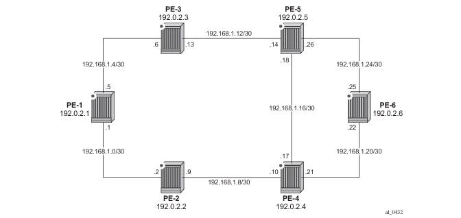
The test topology is shown in Figure 127. All routers participate in a single IS-IS Level-2 area that has traffic-engineering enabled. MPLS is enabled on every interface, but no LSPs are initially provisioned. All routers are BGP speakers and form part of Autonomous system 64496. PE-5 is a Route-Reflector and the remaining routers are IBGP clients for the VPN IPv4 and L2-VPN Address Families. The objective of this example and test topology is to demonstrate how to automatically create transport LSPs using RSVP or LDP-over-RSVP, and then create services that utilize those LSPs. The exchange of BGP routes is needed for those services.
router
policy-options
begin
prefix-list "System-Addresses"
prefix 192.0.2.0/24 prefix-length-range 32-32
exit
policy-statement "Remote-PEs"
entry 10
from
prefix-list "System-Addresses"
exit
action accept
exit
exit
exit
commit
exit
After the route policy is created the user must create an lsp-template containing the common parameters which are used to establish each point-to-point LSPs within the mesh. For an RSVP-TE LSP mesh the
lsp-template must be suffixed with the creation-time attribute
mesh-p2p. Upon creation of the template, CSPF is automatically enabled (and cannot be disabled), and the template must reference a
default-path before it can be placed in a
no shutdown state. In the example contained in the following output, the template refers to a path named “loose” that has no strict or loose hops defined, meaning the system will dynamically calculate the path whilst considering other specified constraints. The
lsp-template in this output also stipulates
fast-reroute facility bypass protection. The default behavior is no node-protect, hence this configuration requests link protection only. Note that one-to-one protection is not supported for automatically created RSVP-TE LSPs; hence facility bypass is the only form of protection supported. Finally the template is placed in a no shutdown state.
Next, the user must associate the lsp-template with the previously defined route-policy, and this is accomplished using the auto-lsp lsp-template command. In this example, the lsp-template “Full-Mesh” is associated with the policy-statement “Remote-PEs” that in turn references a prefix-list containing all system addresses in the test topology. (Up to five policies can be associated with a given lsp-template at any one time.) If a policy associated with an lsp-template is modified to add or remove prefixes, the system immediately re-evaluates the policy/prefix-list to determine if one or more LSPs need to be established, or one or more LSPs need to be torn down.
router
mpls
path "loose"
no shutdown
exit
lsp-template "Full-Mesh" mesh-p2p
default-path "loose"
cspf
fast-reroute facility
exit
no shutdown
exit
auto-lsp lsp-template "Full-Mesh" policy "Remote-PEs"
no shutdown
exit
Once the auto-lsp lsp-template command is entered, the system commences the process of establishing the point-to-point LSPs. The prefixes defined in the prefix-list are checked, and if a prefix corresponds to a router-id that is present in the Traffic-Engineering database, the system instantiates a CSPF computed primary path to that prefix using the parameters specified in the lsp-template. With the previously defined configuration applied at PE-6, the existence of point-to-point RSVP LSPs to every node in the test topology can be verified as shown in the following output. The LSP name is automatically constructed as TemplateName-DestIPv4Address-TunnelId. The LSP name signaled in the Session Attribute object concatenates the LSP name with the path name (for example Full-Mesh-192.0.2.1-61455::loose).
*A:PE-6# show router mpls lsp
===============================================================================
MPLS LSPs (Originating)
===============================================================================
LSP Name To Tun Fastfail Adm Opr
Id Config
-------------------------------------------------------------------------------
Full-Mesh-192.0.2.1-61455 192.0.2.1 61455 Yes Up Up
Full-Mesh-192.0.2.2-61456 192.0.2.2 61456 Yes Up Up
Full-Mesh-192.0.2.3-61457 192.0.2.3 61457 Yes Up Up
Full-Mesh-192.0.2.4-61458 192.0.2.4 61458 Yes Up Up
Full-Mesh-192.0.2.5-61459 192.0.2.5 61459 Yes Up Up
-------------------------------------------------------------------------------
LSPs : 5
===============================================================================
*A:PE-6# show router mpls lsp path "Full-Mesh-192.0.2.1-61455" detail | match expression "LSP Name|Actual Hops" post-lines 4
LSP Name : Full-Mesh-192.0.2.1-61455 Path LSP ID : 44042
From : 192.0.2.6 To : 192.0.2.1
Adm State : Up Oper State : Up
Path Name : loose Path Type : Primary
Path Admin : Up Path Oper : Up
Actual Hops :
192.168.1.25 (192.0.2.6) @ Record Label : N/A
-> 192.168.1.26 (192.0.2.5) @ Record Label : 262143
-> 192.168.1.13 (192.0.2.3) @ Record Label : 262143
-> 192.168.1.5 (192.0.2.1) Record Label : 262143
*A:PE-6# show router tunnel-table
===============================================================================
Tunnel Table (Router: Base)
===============================================================================
Destination Owner Encap TunnelId Pref Nexthop Metric
-------------------------------------------------------------------------------
192.0.2.1/32 rsvp MPLS 61455 7 192.168.1.26 300
192.0.2.2/32 rsvp MPLS 61456 7 192.168.1.21 200
192.0.2.3/32 rsvp MPLS 61457 7 192.168.1.26 200
192.0.2.4/32 rsvp MPLS 61458 7 192.168.1.21 100
192.0.2.5/32 rsvp MPLS 61459 7 192.168.1.26 100
-------------------------------------------------------------------------------
Flags: B = BGP backup route available
===============================================================================
Once the lsp-template is in use and LSPs are instantiated, it is necessary to place the template into a shutdown state to change any parameters that cannot be handled as a Make-Before-Break (MBB). This essentially includes all LSP parameters with the exception of bandwidth and fast-reroute without node-protection. Modification of any other parameters requires a shutdown of the lsp-template and a re-signal of the LSP once the lsp-template is placed in the no shutdown state again. It should be noted however that MBB is supported for timer-based and manual re-signaling of the automatically created LSPs.
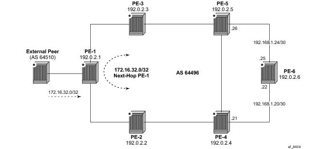
Figure 128 demonstrates the use of IGP shortcuts, prefix 172.16.32.0/20 is advertised to PE-1 from an external peer in AS 64510, which PE-1 subsequently advertises into IBGP, imposing Next-Hop-Self in the process. For more details on IGP short cuts refer to
IGP Shortcuts .
The objective is that PE-6 uses the automatically created LSP to PE-1 as an IGP shortcut (typically implemented in order to maintain a “BGP-free” core). IGP shortcuts for BGP are enabled under the main BGP context using the command igp-shortcut with options for
rsvp-te,
ldp, or
mpls, the last of which will use an RSVP LSP if it is available, and if not, revert to an LDP LSP. Since the test topology only has (automatically created) RSVP-TE LSPs, this option is selected.
router
bgp
igp-shortcut rsvp-te
exit
*A:PE-6# show router route-table 172.16.32.0/20
===============================================================================
Route Table (Router: Base)
===============================================================================
Dest Prefix[Flags] Type Proto Age Pref
Next Hop[Interface Name] Metric
-------------------------------------------------------------------------------
172.16.32.0/20 Remote BGP 00h08m16s 170
192.0.2.1 (tunneled:RSVP:61455) 0
-------------------------------------------------------------------------------
No. of Routes: 1
Flags: L = LFA nexthop available B = BGP backup route available
n = Number of times nexthop is repeated
===============================================================================
Layer 3 VPNs can utilize the automatically created LSPs by using the auto-bind feature configured with the
rsvp-te or
mpls options. The mpls option allows the system to use an RSVP LSP if one exists, and if not to revert to an LDP-based LSP. A VPRN is configured in this manner at PE-1 and PE-6. PE-1 is configured with a loopback address of 172.16.1.1/24 and advertises the VPN IPv4 prefix 172.16.1.0/24 into IBGP, whilst PE-6 is configured with a loopback address of 172.16.6.1/24 and advertises the VPN IPv4 prefix 172.16.6.0/24 into IBGP. The next output illustrates the configuration at PE-6. The only difference at PE-1 is the IP address assigned to the loopback interface.
service
vprn 1 customer 1 create
route-distinguisher 64496:1
auto-bind mpls
vrf-target target:64496:1
interface "loopback" create
address 172.16.6.1/24
loopback
exit
no shutdown
exit
Before a VPN IPv4 prefix is considered valid by a receiving SR OS PE router, it must be able to resolve the BGP Next-Hop to an LSP in the tunnel table (if not, the prefix is held in RIB-In and flagged as
invalid). At PE-6 it is possible to verify that the VPN IPv4 prefix 172.16.1.0/24 received from PE-1 is correctly resolved simply by looking at the VPRN-specific route table. In the output below the VPN IPv4 prefix 172.16.1.0/24 with a Next-Hop of PE-1 (192.0.2.1) is correctly resolved to an RSVP LSP with a Tunnel Id of 61455.
*A:PE-6# show router 1 route-table 172.16.1.0/24
===============================================================================
Route Table (Service: 1)
===============================================================================
Dest Prefix[Flags] Type Proto Age Pref
Next Hop[Interface Name] Metric
-------------------------------------------------------------------------------
172.16.1.0/24 Remote BGP VPN 01h51m58s 170
192.0.2.1 (tunneled:RSVP:61455) 0
-------------------------------------------------------------------------------
No. of Routes: 1
Flags: L = LFA nexthop available B = BGP backup route available
n = Number of times nexthop is repeated
===============================================================================
This can be implemented using static provisioning of peers as shown in the next output, or it can be done using automatic creation of T-LDP sessions. Regardless of the method, a reciprocal configuration must exist at both peer endpoints. The static per-peer configuration is applied in the targeted-session context and specifies the remote peer system IP address, and the keyword
tunneling, which enables tunneling of LDP FECs over RSVP LSPs with a far-end address matching that of the T-LDP peer. At a global level, the
prefer-tunnel-in-tunnel command is shown, but is only required when a next-hop router advertises a FEC over link-level LDP and T-LDP. In this case, by default the system would prefer the link-level LDP tunnel, so the
prefer-tunnel-in-tunnel instructs the system to prefer an LDP-over-RSVP tunnel if it is available. Although link-layer LDP is not present in the test topology, the command is included because the presence of link-layer LDP is common.
router
ldp
prefer-tunnel-in-tunnel
interface-parameters
exit
targeted-session
peer 192.0.2.1
tunneling
exit
exit
exit
no shutdown
exit
The next output provides an example using automatic creation of T-LDP sessions. Here, no explicit reference is made to specific peers, but rather a peer-template is configured containing the parameters which apply to all T-LDP sessions spawned by this template. In this example, only the
tunneling command is required. A
peer-template-map is then used to create a mapping between the
peer-template (TLDP-Mesh) and a
policy defining the IP addresses of remote nodes to which T-LDP sessions should be established. In this example, the policy “Remote-PEs” is the same policy previously used by the auto-created RSVP LSP mesh.
router
ldp
prefer-tunnel-in-tunnel
interface-parameters
exit
targeted-session
peer-template "TLDP-Mesh"
tunneling
exit
peer-template-map peer-template "TLDP-Mesh" policy "Remote-PEs"
exit
no shutdown
exit
*A:PE-6# show router ldp peer 192.0.2.1 detail
===============================================================================
LDP Peers (Detail)
===============================================================================
-------------------------------------------------------------------------------
Peer 192.0.2.1
-------------------------------------------------------------------------------
Admin State : Up Oper State : Up
Up Time : 0d 00:00:16
Hold Time : 45 Hello Factor : 3
Oper Hold Time : 45
Hello Reduction : Disabled Hello Reduction Fact*: 3
Keepalive Timeout : 40 Keepalive Factor : 4
Passive Mode : Disabled Last Modified : 01/20/14 16:26:57
Active Adjacencies : 1 Auto Created : Yes
Creator : template Template Name : SDP-Mesh
Tunneling : Enabled
Lsp Name : None
Local LSR : None
BFD Status : Disabled
Multicast Traffic : Disabled
===============================================================================
* indicates that the corresponding row element may have been truncated.
To create VPLS services using dynamically-created SDPs, BGP Auto-Discovery (BGP-AD) must be used together with LDP (or BGP) pseudowire signaling, for more details see LDP VPLS using BGP-Auto Discovery . In the following output PE-6 uses BGP-AD and LDP signaling. (The same configuration is applied at PE-1.) The
vpls-id is configured in the
bgp-ad context. The
vpls-id is a network-wide identifier assigned to all VPLS Switch Instances (VSIs) belonging to the same VPLS, and is carried in VPLS Network Layer Reachability Information (NLRI) as an Extended Community attribute. A second parameter used for BGP-AD and carried in the VPLS NLRI is the VSI-ID, which uniquely identifies each VSI. The VSI-ID is automatically derived from the global ASN, VPLS service ID, and the system IP address. To automatically create SDPs, the
bgp context of the VPLS service refers to a
pw-template defining the parameters of the pseudowire. In this example, the use of the hash (entropy) label is enabled in the pseudowire template, and a
split-horizon-group, SHG, is applied.
service
pw-template 2 create
hash-label
split-horizon-group "SHG"
exit
exit
vpls 2 customer 1 create
bgp
pw-template-binding 2
exit
exit
bgp-ad
vpls-id 64496:2
no shutdown
exit
stp
shutdown
exit
sap 1/1/3:2.2 create
exit
no shutdown
exit
*A:PE-6# show service id 2 base | match "BGP Auto-discovery" post-lines 20
BGP Auto-discovery Information
-------------------------------------------------------------------------------
Admin State : Up Vpls Id : 64496:2
Route Dist : 64496:2 Prefix : 192.0.2.6
Rte-Target Import : 64496:2 Rte-Target Export : 64496:2
Vsi-Import : None
Vsi-Export : None
PW-Template Id : 2 PW-Template SHG : None
Oper Group : None
Import Rte-Tgt : None
-------------------------------------------------------------------------------
-------------------------------------------------------------------------------
Service Access & Destination Points
-------------------------------------------------------------------------------
Identifier Type AdmMTU OprMTU Adm Opr
-------------------------------------------------------------------------------
sap:1/1/3:2.2 qinq 1522 1522 Up Up
sdp:17407:4294967295 SB(192.0.2.1) BgpAd 0 9178 Up Up
===============================================================================
To create Epipe services using dynamically created SDPs, two options exist. Either LDP FEC 129 signaling can be used, which in turn dictates the presence of pseudowire routing information, or BGP-VPWS based signaling can be used, for more details see BGP Virtual Private Wire Services . This example illustrates the use of BGP-VPWS, but in either case, only single-segment pseudowires are supported. The next output shows the configuration requirements for a basic BGP-based Epipe service at PE-6. Once again a
pw-template is used to define the characteristics of the pseudowire, and this template is referenced in the
bgp context of the Epipe service. The
bgp context is also where the
route-distinguisher and
route-target values are configured, which are carried in the VPWS NLRI and Extended Communities respectively. The
ve-name,
ve-id, and
remote-ve-name are all configured in the
bgp-vpws context. The
ve-id is carried in the VPWS NLRI, and when a PE router receives a VPWS NLRI to try to establish an Epipe service, the
ve-id from the NLRI is validated against the
ve-id configured in the
remote-ve-name. These must match before the Epipe becomes operational.
service
pw-template 3 create
hash-label
exit
epipe 3 customer 1 create
bgp
route-distinguisher 64496:3
route-target export target:64496:3 import target:64496:3
pw-template-binding 3
exit
exit
bgp-vpws
ve-name "PE-6"
ve-id 6
exit
remote-ve-name "PE-1"
ve-id 1
exit
no shutdown
exit
sap 1/1/3:3.3 create
exit
no shutdown
exit
*A:PE-6# show service id 3 base | match "Service Access" post-lines 6
Service Access & Destination Points
-------------------------------------------------------------------------------
Identifier Type AdmMTU OprMTU Adm Opr
-------------------------------------------------------------------------------
sap:1/1/3:3.3 qinq 1522 1522 Up Up
sdp:17406:4294967293 SB(192.0.2.1) BgpVpws 0 9178 Up Up
===============================================================================
The first requirement is to create an lsp-template containing the common parameters used to establish each single-hop LSP. For a single-hop LSP mesh the
lsp-template must be suffixed with the creation-time attribute
one-hop-p2p. Upon creation of the template,
cspf is automatically enabled (and cannot be disabled), and the
hop-limit is set to a value of
2. The hop-limit defines the number of nodes the LSP may traverse, and since these are single-hop LSPs to adjacent neighbors a limit of 2 is sufficient. The template must also reference a
default-path before it can be placed in the no shutdown state. The example below references a path named “loose” that has no strict or loose hops defined. When the RSVP PATH message is actually generated to create the one-hop LSP, it contains one strict-hop to the interface address of the neighbor; and as destination the system address of the adjacent node.
The next requirement is to trigger the creation of single-hop LSPs, and this is achieved using the auto-lsp lsp-template command. In this example, the lsp-template “Single-Hop” is referenced, and the command is completed with the keyword
one-hop to indicate the creation of single-hop LSPs. Unlike an RSVP-TE mesh there is no requirement to reference a route-policy.
router
mpls
path "loose"
no shutdown
exit
lsp-template "Single-Hop" one-hop-p2p
default-path "loose"
cspf
hop-limit 2
no shutdown
exit
auto-lsp lsp-template "Single-Hop" one-hop
no shutdown
exit
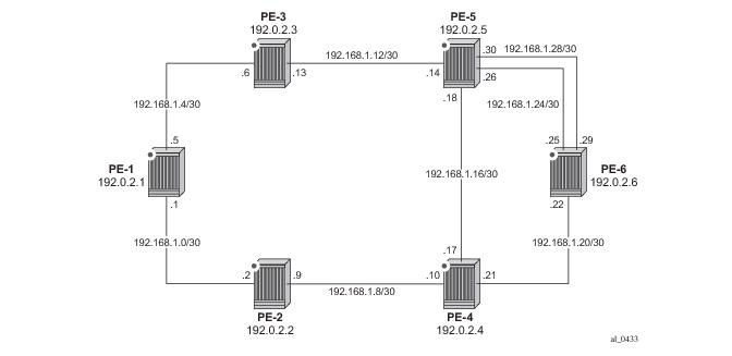
Once the auto-lsp lsp-template command is entered, the system starts the process of establishing the single-hop LSPs. A check is made of the TE database for every TE link to a directly connected IGP neighbor, and a single-hop LSP is established across each TE link. The output below is taken from PE-6 and shows the automatically created single-hop LSPs. The LSP names are automatically constructed as TemplateName-DestIPv4Address-TunnelId. The LSP name signaled in the Session Attribute object concatenates the LSP name with the path name (for example Single-Hop-192.0.2.4-61499::loose). Recall from Figure 3 that PE-6 has a single TE-enabled link to PE-4, and two TE-enabled links to PE-5, hence with ECMP=2 there is one LSP to PE-4 (192.0.2.4) and two LSPs to PE-5 (192.0.2.5). Note that if ECMP=1 only one single-hop LSP would be signaled to PE-5.
*A:PE-6# show router mpls lsp
===============================================================================
MPLS LSPs (Originating)
===============================================================================
LSP Name To Tun Fastfail Adm Opr
Id Config
-------------------------------------------------------------------------------
Single-Hop-192.0.2.4-61499 192.0.2.4 61499 No Up Up
Single-Hop-192.0.2.5-61500 192.0.2.5 61500 No Up Up
Single-Hop-192.0.2.5-61501 192.0.2.5 61501 No Up Up
-------------------------------------------------------------------------------
LSPs : 3
===============================================================================
*A:PE-6# show router ldp session
==============================================================================
LDP Sessions
==============================================================================
Peer LDP Id Adj Type State Msg Sent Msg Recv Up Time
------------------------------------------------------------------------------
192.0.2.4:0 Targeted Established 32518 32652 2d 00:40:28
192.0.2.5:0 Targeted Established 32509 32561 2d 00:40:23
------------------------------------------------------------------------------
No. of Sessions: 5
==============================================================================
To validate the ECMP load-balancing capability, PE-5 is configured to advertise prefix 172.16.5.0/24 to PE-6. In turn, PE-6 is configured for ibgp-multipath to enable load-balancing over IGP links to the BGP Next-Hop address,
igp-shortcut ldp to enable tunneling of traffic destined towards the BGP Next-Hop in MPLS, and
ecmp 2.
router
ecmp 2
bgp
ibgp-multipath
igp-shortcut ldp
exit
*A:PE-6# show router bgp routes 172.16.5.0/24
===============================================================================
BGP Router ID:192.0.2.6 AS:64496 Local AS:64496
===============================================================================
Legend -
Status codes : u - used, s - suppressed, h - history, d - decayed, * - valid
Origin codes : i - IGP, e - EGP, ? - incomplete, > - best, b - backup
===============================================================================
BGP IPv4 Routes
===============================================================================
Flag Network LocalPref MED
Nexthop Path-Id Label
As-Path
-------------------------------------------------------------------------------
u*>i 172.16.5.0/24 100 None
192.0.2.5 None -
No As-Path
-------------------------------------------------------------------------------
Routes : 1
===============================================================================
*A:PE-6# show router fib 1 192.0.2.5/32
===============================================================================
FIB Display
===============================================================================
Prefix Protocol
NextHop
-------------------------------------------------------------------------------
192.0.2.5/32 ISIS
192.168.1.26 (int-PE-6-PE-5_1)
192.168.1.30 (int-PE-6-PE-5_2)
-------------------------------------------------------------------------------
Total Entries : 1
-------------------------------------------------------------------------------
===============================================================================