Automatic selection of ABRs is supported, in this way the head-end node can work with an empty primary path. When the to field of an LSP definition is in a different area/level than the head-end node, CSPF will automatically compute the segment to the exit ABR router which advertised the prefix and which is currently the best path for resolving the prefix in Route Table Manager (RTM).
Since the description of the RRO Node ID sub-object in RFC 4561 (Definition of a Record Route Object (RRO) Node-Id Sub-Object) is not clear about the format of the included node-address (S), interface-address (I) and label (L), the system is programmed to understand multiple formats: IL, SL, ISL, SIL, SLI, ILSL and SLIL. The system uses the SLIL (node-adddress, label, interface-address, label) format to include the node-ID itself.
XRO object inclusion (RFC 4874, Exclude Routes - Extension to Resource ReserVation Protocol-Traffic Engineering) in bypass RSVP PATH messages is required to exclude the protected ABR from the bypass path. The XRO object is filled in with ABRs system IP address.
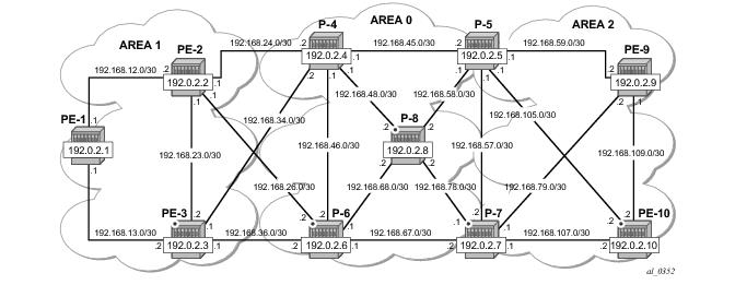
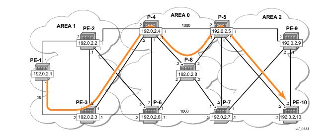
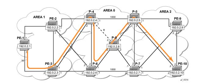
Figure 148 shows the LSP path intended to be setup through the network. An empty MPLS path is used. At the head-end node (PE-1), the destination address (PE-10) is learned via ABR node P-4 and ABR node P-5.
*A:PE-1# show router ospf opaque-database
===============================================================================
OSPF Opaque Link State Database (Type : All)
===============================================================================
Type Id Link State Id Adv Rtr Id Age Sequence Cksum
-------------------------------------------------------------------------------
Area 0.0.0.1 1.0.0.1 192.0.2.1 357 0x800000ef 0xb622
Area 0.0.0.1 1.0.0.2 192.0.2.1 619 0x800001dc 0xc193
Area 0.0.0.1 1.0.0.3 192.0.2.1 461 0x800001dd 0xe42
Area 0.0.0.1 1.0.0.1 192.0.2.2 1434 0x800000f5 0xae22
Area 0.0.0.1 1.0.0.2 192.0.2.2 498 0x800001e8 0x85c3
Area 0.0.0.1 1.0.0.3 192.0.2.2 285 0x800001e3 0x92a2
Area 0.0.0.1 1.0.0.4 192.0.2.2 428 0x800001e7 0xd854
Area 0.0.0.1 1.0.0.5 192.0.2.2 713 0x800001e9 0x7ba8
Area 0.0.0.1 1.0.0.1 192.0.2.3 424 0x800000f1 0xba18
Area 0.0.0.1 1.0.0.2 192.0.2.3 763 0x800001e3 0xcb7f
Area 0.0.0.1 1.0.0.3 192.0.2.3 183 0x800001e5 0x6ac8
Area 0.0.0.1 1.0.0.4 192.0.2.3 294 0x800001e4 0x6fab
Area 0.0.0.1 1.0.0.5 192.0.2.3 763 0x800001ea 0xa04
Area 0.0.0.1 1.0.0.1 192.0.2.4 4 0x800000ed 0xc60e
Area 0.0.0.1 1.0.0.5 192.0.2.4 1395 0x800001e1 0x9a97
Area 0.0.0.1 1.0.0.6 192.0.2.4 1030 0x800001e1 0x3dde
Area 0.0.0.1 1.0.0.1 192.0.2.6 1367 0x800000ee 0xcc03
Area 0.0.0.1 1.0.0.5 192.0.2.6 535 0x800001e2 0xbd58
Area 0.0.0.1 1.0.0.6 192.0.2.6 709 0x800001de 0xf1f
-------------------------------------------------------------------------------
No. of Opaque LSAs: 19
===============================================================================
Note in Figure 148 that the LSP should pass through node PE-3 and node P-8. In order to prefer a dynamic path from PE-1 to P-4 via PE-3 rather than through PE-2, it is necessary to configure on PE-1 a lower IGP metric on the interface to PE-3 (the default metric is derived from the interface speed; in this case the metric is 100 by default).
*A:PE-1>config>router>ospf# area 1 interface "int-PE-1-PE-3" metric 10
Similarly, in the core, the IGP metric between P-4 <=> P-5 and P-6
<=> P-7 is increased to force the LSP to pass the core P-8 node.
*A:P-4>config>router>ospf# area 0 interface "int-P-4-P-5" metric 1000
*A:P-6>config>router>ospf# area 0 interface "int-P-6-P-7" metric 1000
*A:PE-1# configure router mpls
*A:PE-1>config>router>mpls# path "path-PE-10" no shutdown
*A:PE-1>config>router>mpls#
*A:PE-1>config>router>mpls# lsp "LSP-PE-1-PE-10" to 192.0.2.10
*A:PE-1>config>router>mpls# lsp "LSP-PE-1-PE-10" cspf
*A:PE-1>config>router>mpls# lsp "LSP-PE-1-PE-10" fast-reroute facility
*A:PE-1>config>router>mpls# lsp "LSP-PE-1-PE-10" primary "path-PE-10" no shutdown
*A:PE-1>config>router>mpls# lsp "LSP-PE-1-PE-10" no shutdown
*A:P-4# configure router mpls cspf-on-loose-hop
*A:P-6# configure router mpls cspf-on-loose-hop
*A:P-7# configure router mpls cspf-on-loose-hop
*A:P-5# configure router mpls cspf-on-loose-hop
*A:PE-1# show router mpls lsp "LSP-PE-1-PE-10" path detail
...
From : 192.0.2.1 To : 192.0.2.10
Adm State : Up Oper State : Down
…
Failure Code: badNode Failure Node: 192.168.24.2
*A:PE-1# debug router rsvp packet path detail
2 2013/08/20 16:29:20.89 UTC MINOR: DEBUG #2001 Base RSVP
"RSVP: PATH Msg
Send PATH From:192.0.2.1, To:192.0.2.10
TTL:255, Checksum:0x88f3, Flags:0x0
Session - EndPt:192.0.2.10, TunnId:2, ExtTunnId:192.0.2.1
SessAttr - Name:LSP-PE-1-PE-10::path-PE-10
SetupPri:7, HoldPri:0, Flags:0x17
RSVPHop - Ctype:1, Addr:192.168.13.1, LIH:3
TimeValue - RefreshPeriod:30
SendTempl - Sender:192.0.2.1, LspId:56852
SendTSpec - Ctype:QOS, CDR:0.000 bps, PBS:0.000 bps, PDR:infinity
MPU:20, MTU:1564
LabelReq - IfType:General, L3ProtID:2048
RRO - IpAddr:192.168.13.1, Flags:0x0
ERO - IPv4Prefix 192.168.13.2/32, Strict
IPv4Prefix 192.168.34.2/32, Strict
IPv4Prefix 192.0.2.10/32, Loose
FRRObj - SetupPri:7, HoldPri:0, HopLimit:16, BW:0.000 bps, Flags:0x2
ExcAny:0x0, IncAny:0x0, IncAll:0x0
"
*A:P-4# debug router rsvp packet path detail
11 2013/08/20 08:54:40.97 UTC MINOR: DEBUG #2001 Base RSVP
"RSVP: PATH Msg
Send PATH From:192.0.2.1, To:192.0.2.10
TTL:253, Checksum:0x176f, Flags:0x0
Session - EndPt:192.0.2.10, TunnId:2, ExtTunnId:192.0.2.1
SessAttr - Name:LSP-PE-1-PE-10::path-PE-10
SetupPri:7, HoldPri:0, Flags:0x17
RSVPHop - Ctype:1, Addr:192.168.48.1, LIH:4
TimeValue - RefreshPeriod:30
SendTempl - Sender:192.0.2.1, LspId:56852
SendTSpec - Ctype:QOS, CDR:0.000 bps, PBS:0.000 bps, PDR:infinity
MPU:20, MTU:1564
LabelReq - IfType:General, L3ProtID:2048
RRO - IpAddr:192.168.48.1, Flags:0x0
IpAddr:192.168.34.1, Flags:0x0
IpAddr:192.168.13.1, Flags:0x0
ERO - IPv4Prefix 192.168.48.2/32, Strict
IPv4Prefix 192.168.58.1/32, Strict
IPv4Prefix 192.0.2.10/32, Loose
FRRObj - SetupPri:7, HoldPri:0, HopLimit:16, BW:0.000 bps, Flags:0x2
ExcAny:0x0, IncAny:0x0, IncAll:0x0
"
*A:P-5# debug router rsvp packet path detail
4 2013/08/20 08:25:04.70 UTC MINOR: DEBUG #2001 Base RSVP
"RSVP: PATH Msg
Send PATH From:192.0.2.1, To:192.0.2.10
TTL:251, Checksum:0xbfcd, Flags:0x0
Session - EndPt:192.0.2.10, TunnId:2, ExtTunnId:192.0.2.1
SessAttr - Name:LSP-PE-1-PE-10::path-PE-10
SetupPri:7, HoldPri:0, Flags:0x17
RSVPHop - Ctype:1, Addr:192.168.105.1, LIH:5
TimeValue - RefreshPeriod:30
SendTempl - Sender:192.0.2.1, LspId:56852
SendTSpec - Ctype:QOS, CDR:0.000 bps, PBS:0.000 bps, PDR:infinity
MPU:20, MTU:1564
LabelReq - IfType:General, L3ProtID:2048
RRO - IpAddr:192.168.105.1, Flags:0x0
IpAddr:192.168.58.2, Flags:0x0
IpAddr:192.168.48.1, Flags:0x0
IpAddr:192.168.34.1, Flags:0x0
IpAddr:192.168.13.1, Flags:0x0
ERO - IPv4Prefix 192.168.105.2/32, Strict
FRRObj - SetupPri:7, HoldPri:0, HopLimit:16, BW:0.000 bps, Flags:0x2
ExcAny:0x0, IncAny:0x0, IncAll:0x0
"
*A:PE-1# show router mpls lsp "LSP-PE-1-PE-10" path detail
===============================================================================
MPLS LSP LSP-PE-1-PE-10 Path (Detail)
===============================================================================
Legend :
@ - Detour Available # - Detour In Use
b - Bandwidth Protected n - Node Protected
s - Soft Preemption
S - Strict L - Loose
A - ABR
===============================================================================
-------------------------------------------------------------------------------
LSP LSP-PE-1-PE-10 Path path-PE-10
-------------------------------------------------------------------------------
LSP Name : LSP-PE-1-PE-10 Path LSP ID : 56852
From : 192.0.2.1 To : 192.0.2.10
Adm State : Up Oper State : Up
Path Name : path-PE-10 Path Type : Primary
Path Admin : Up Path Oper : Up
OutInterface: 1/1/1 Out Label : 131071
Path Up Time: 0d 01:05:21 Path Dn Time: 0d 00:00:00
Retry Limit : 0 Retry Timer : 30 sec
RetryAttempt: 0 NextRetryIn : 0 sec
Adspec : Disabled Oper Adspec : Disabled
CSPF : Enabled Oper CSPF : Enabled
Least Fill : Disabled Oper LeastF*: Disabled
FRR : Enabled Oper FRR : Enabled
FRR NodePro*: Enabled Oper FRR NP : Enabled
FR Hop Limit: 16 Oper FRHopL*: 16
FR Prop Adm*: Disabled Oper FRProp*: Disabled
Prop Adm Grp: Disabled Oper PropAG : Disabled
Inter-area : True
Neg MTU : 1560 Oper MTU : 1560
Bandwidth : No Reservation Oper Bw : 0 Mbps
Hop Limit : 255 Oper HopLim*: 255
Record Route: Record Oper RecRou*: Record
Record Label: Record Oper RecLab*: Record
SetupPriori*: 7 Oper SetupP*: 7
Hold Priori*: 0 Oper HoldPr*: 0
Class Type : 0 Oper CT : 0
Backup CT : None
MainCT Retry: n/a
Rem :
MainCT Retry: 0
Limit :
Include Grps: Oper InclGr*:
None None
Exclude Grps: Oper ExclGr*:
None None
Adaptive : Enabled Oper Metric : 110
Preference : n/a
Path Trans : 21 CSPF Queries: 11
Failure Code: noError Failure Node: n/a
ExplicitHops:
No Hops Specified
Actual Hops :
192.168.13.1 (192.0.2.1) @ n Record Label : N/A
-> 192.168.13.2 (192.0.2.3) @ n Record Label : 131071
-> 192.168.34.2 (192.0.2.4) @ n Record Label : 131071
-> 192.0.2.8 (192.0.2.8) @ n Record Label : 131070
-> 192.168.48.2 @ n Record Label : 131070
-> 192.0.2.5 (192.0.2.5) @ Record Label : 131071
-> 192.168.58.1 @ Record Label : 131071
-> 192.0.2.10 (192.0.2.10) Record Label : 131071
-> 192.168.105.2 Record Label : 131071
ComputedHops:
192.168.13.1(S)
-> 192.168.13.2(S)
-> 192.168.34.2(SA)
-> 192.0.2.10(L)
ResigEligib*: False
LastResignal: n/a CSPF Metric : 110
===============================================================================
* indicates that the corresponding row element may have been truncated.
*A:PE-3# debug router rsvp packet path detail
13 2013/08/20 07:56:10.87 UTC MINOR: DEBUG #2001 Base RSVP
"RSVP: PATH Msg
Send PATH From:192.0.2.3, To:192.0.2.8
TTL:17, Checksum:0x907f, Flags:0x0
Session - EndPt:192.0.2.8, TunnId:61445, ExtTunnId:192.0.2.3
SessAttr - Name:bypass-node192.0.2.4
SetupPri:7, HoldPri:0, Flags:0x2
RSVPHop - Ctype:1, Addr:192.168.36.1, LIH:3
TimeValue - RefreshPeriod:30
SendTempl - Sender:192.0.2.3, LspId:10
SendTSpec - Ctype:QOS, CDR:0.000 bps, PBS:0.000 bps, PDR:infinity
MPU:20, MTU:1564
LabelReq - IfType:General, L3ProtID:2048
RRO - IpAddr:192.168.36.1, Flags:0x0
ERO - IPv4Prefix 192.168.36.2/32, Strict
IPv4Prefix 192.0.2.8/32, Loose
XRO - IPv4Prefix: 192.0.2.4/32, Attribute: Node, LBit: Exclude
AdSpec - General BreakBit:0, NumISHops:0, PathBwEstimate:0
MinPathLatency:4294967295, CompPathMTU:1564
Controlled BreakBit:0
"
*A:P-8# configure router rsvp node-id-in-rro include
*A:PE-10# configure router rsvp node-id-in-rro include
The default is node-id-in-rro exclude. As an example, the RESV message received on PLR node (PE-3) is shown below. The RRO contains the MP node (P-8) information in SLIL format:
*A:PE-3# debug router rsvp packet resv detail
18 2013/08/20 08:08:05.39 UTC MINOR: DEBUG #2001 Base RSVP
"RSVP: RESV Msg
Send RESV From:192.168.13.2, To:192.168.13.1
TTL:255, Checksum:0x31f7, Flags:0x0
Session - EndPt:192.0.2.10, TunnId:2, ExtTunnId:192.0.2.1
RSVPHop - Ctype:1, Addr:192.168.13.2, LIH:3
TimeValue - RefreshPeriod:30
Style - SE
FlowSpec - Ctype:QOS, CDR:0.000 bps, PBS:0.000 bps, PDR:infinity
MPU:20, MTU:1560, RSpecRate:0, RSpecSlack:0
FilterSpec - Sender:192.0.2.1, LspId:56852, Label:131071
RRO - …
SystemIp:192.0.2.8, Flags:0x29
Label:131070, Flags:0x1
InterfaceIp:192.168.48.2, Flags:0x9
Label:131070, Flags:0x1
…
""
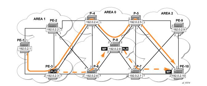
Figure 149 shows the two dynamic ABR node protections that are signalled for this LSP.
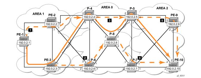
Figure 150 shows the complete picture of all the FRR protections and indicates each node/link protection in the setup.
*A:PE-1# show router mpls lsp "LSP-PE-1-PE-10" path detail
…
LSP Name : LSP-PE-1-PE-10 Path LSP ID : 56852
From : 192.0.2.1 To : 192.0.2.10
Adm State : Up Oper State : Up
Path Name : path-PE-10 Path Type : Primary
Path Admin : Up Path Oper : Up
…
Inter-area : True
…
Actual Hops :
192.168.13.1 (192.0.2.1) @ n (1) Record Label : N/A
-> 192.168.13.2 (192.0.2.3) @ n (2) Record Label : 131071
-> 192.168.34.2 (192.0.2.4) @ n (3) Record Label : 131071
-> 192.0.2.8 (192.0.2.8) @ n (4) Record Label : 131070
-> 192.168.48.2 @ n (4) Record Label : 131070
-> 192.0.2.5 (192.0.2.5) @ (5) Record Label : 131071
-> 192.168.58.1 @ (5) Record Label : 131071
-> 192.0.2.10 (192.0.2.10) Record Label : 131071
-> 192.168.105.2 Record Label : 131071
…
Note: The node-id-in-rro include command is not mandatory for this example on ABR node P-5 but to be future save (for example, to cover cases where
a new LSP is established in the network and P-5 acts as an MP node while the corresponding PLR node for that new LSP is in another area), this RSVP command can be enabled on all possible MP nodes in the network.
*A:PE-3# show router mpls bypass-tunnel protected-lsp detail
===============================================================================
MPLS Bypass Tunnels (Detail)
===============================================================================
-------------------------------------------------------------------------------
bypass-node192.0.2.4
-------------------------------------------------------------------------------
To : 192.0.2.8 State : Up
Out I/F : 1/1/4 Out Label : 131070
Up Time : 0d 01:41:04 Active Time : n/a
Reserved BW : 0 Kbps Protected LSP Count : 1
Type : Dynamic
Setup Priority : 7 Hold Priority : 0
Class Type : 0
Exclude Node : 192.0.2.4 Inter-Area : True
Computed Hops :
192.168.36.1(S) Egress Admin Groups : None
-> 192.168.36.2(SA) Egress Admin Groups : None
-> 192.0.2.8(L) Egress Admin Groups : None
Actual Hops :
192.168.36.1 (192.0.2.3) Record Label : N/A
-> 192.168.36.2 (192.0.2.6) Record Label : 131070
-> 192.0.2.8 (192.0.2.8) Record Label : 131069
-> 192.168.68.2 Record Label : 131069
Protected LSPs -
LSP Name : LSP-PE-1-PE-10::path-PE-10
From : 192.0.2.1 To : 192.0.2.10
Avoid Node/Hop : 192.0.2.4 Downstream Label : 131070
Bandwidth : 0 Kbps
In Figure 151 the LSP path avoids the link between P-4 and P-8. This will be done by assigning admin group red to the link between P-4 and P-8 and then configuring the LSP to exclude the admin group red.
*A:P-4# configure router mpls
*A:P-4>config>router>mpls# admin-group "red" 11
*A:P-4>config>router>mpls# interface "int-P-4-P-8" admin-group "red"
*A:Px# configure router mpls admin-group "red" 11
*A:PE-1>config>router>mpls# info
----------------------------------------------
admin-group "red" 11
…
path "path-PE-10"
no shutdown
exit
lsp "LSP-PE-1-PE-10"
to 192.0.2.10
cspf
exclude "red"
propagate-admin-group
fast-reroute facility
exit
no shutdown
exit
no shutdown
----------------------------------------------
Note the propagate-admin-group command is required to include the admin group properties in the SA object of the PATH message. Admin-group value is mapped to a 32-bitmap. In this example, value 11 means that the 12
th bit is set, which means in binary 100000000000 or hex 0x800.
*A:PE-1# debug router rsvp packet path detail
48 2013/08/20 18:41:05.89 UTC MINOR: DEBUG #2001 Base RSVP
"RSVP: PATH Msg
Send PATH From:192.0.2.1, To:192.0.2.10
TTL:255, Checksum:0x80db, Flags:0x0
Session - EndPt:192.0.2.10, TunnId:2, ExtTunnId:192.0.2.1
SessAttr - Name:LSP-PE-1-PE-10::path-PE-10
SetupPri:7, HoldPri:0, Flags:0x17
Ctype:RA, ExcAny:0x800, IncAny:0x0, IncAll:0x0
RSVPHop - Ctype:1, Addr:192.168.13.1, LIH:3
TimeValue - RefreshPeriod:30
SendTempl - Sender:192.0.2.1, LspId:56858
SendTSpec - Ctype:QOS, CDR:0.000 bps, PBS:0.000 bps, PDR:infinity
MPU:20, MTU:1564
LabelReq - IfType:General, L3ProtID:2048
RRO - IpAddr:192.168.13.1, Flags:0x0
ERO - IPv4Prefix 192.168.13.2/32, Strict
IPv4Prefix 192.168.34.2/32, Strict
IPv4Prefix 192.0.2.10/32, Loose
FRRObj - SetupPri:7, HoldPri:0, HopLimit:16, BW:0.000 bps, Flags:0x2
ExcAny:0x0, IncAny:0x0, IncAll:0x0
"
*A:P-4# debug router rsvp packet path detail
9 2013/08/20 11:16:08.94 UTC MINOR: DEBUG #2001 Base RSVP
"RSVP: PATH Msg
Send PATH From:192.0.2.1, To:192.0.2.10
TTL:253, Checksum:0xef94, Flags:0x0
Session - EndPt:192.0.2.10, TunnId:2, ExtTunnId:192.0.2.1
SessAttr - Name:LSP-PE-1-PE-10::path-PE-10
SetupPri:7, HoldPri:0, Flags:0x17
Ctype:RA, ExcAny:0x800, IncAny:0x0, IncAll:0x0
…
ERO - IPv4Prefix 192.168.46.2/32, Strict
IPv4Prefix 192.168.68.2/32, Strict
IPv4Prefix 192.168.58.1/32, Strict
IPv4Prefix 192.0.2.10/32, Loose
…
*A:PE-1# show router mpls lsp "LSP-PE-1-PE-10" path detail
…
LSP Name : LSP-PE-1-PE-10 Path LSP ID : 56858
From : 192.0.2.1 To : 192.0.2.10
Adm State : Up Oper State : Up
Path Name : path-PE-10 Path Type : Primary
Path Admin : Up Path Oper : Up
…
Actual Hops :
192.168.13.1 (192.0.2.1) @ n Record Label : N/A
-> 192.168.13.2 (192.0.2.3) @ n Record Label : 131071
-> 192.168.34.2 (192.0.2.4) @ n Record Label : 131071
-> 192.0.2.6 (192.0.2.6) @ n Record Label : 131071
-> 192.168.46.2 @ n Record Label : 131071
-> 192.0.2.8 (192.0.2.8) @ Record Label : 131071
-> 192.168.68.2 @ Record Label : 131071
-> 192.0.2.5 (192.0.2.5) @ Record Label : 131071
-> 192.168.58.1 @ Record Label : 131071
-> 192.0.2.10 (192.0.2.10) Record Label : 131071
-> 192.168.105.2 Record Label : 131071
…
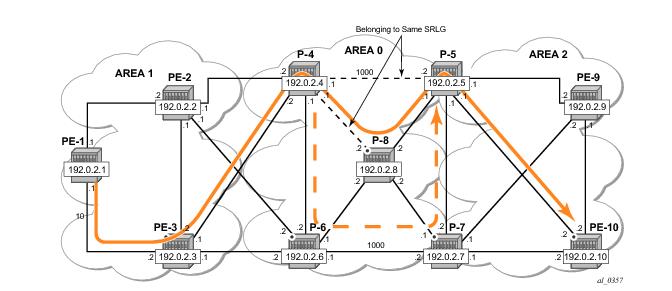
Consider the setup in Figure 152, where an inter-area LSP is setup from PE-1 to PE-10 and the path goes through P-8 because of a lower IGP metric. To protect against a node failure of P-8, P-4 (PLR) would normally setup an FRR backup directly to P-5 (MP), because of the lower IGP metric (P-4 to P-5:1000) compared to the IGP traffic via P-6 (P-4 to P-6 to P-7 to P-5:1200).
However, imagine that in this setup the P-4 <=> P-5 link and the P-4
<=> P-8 links are part of the same transmission bundle. In this case a cut of that fiber bundle will bring down both the primary and the backup path.
*A:P-4# configure router mpls
*A:P-4>config>router>mpls# srlg-group "bundle-red" value 1
*A:P-4>config>router>mpls# interface "int-P-4-P-5" srlg-group "bundle-red"
*A:P-4>config>router>mpls# interface "int-P-4-P-8" srlg-group "bundle-red"
*A:P-4>config>router>mpls#
*A:P-4>config>router>mpls# srlg-frr strict
*A:Px# configure router mpls srlg-group "bundle-red" value 1
*A:P-4# configure router mpls
*A:PE-1>config>router>mpls# info
----------------------------------------------
…
lsp "PE-10"
to 192.0.2.10
cspf
cspf-to-first-loose
fast-reroute facility
exit
primary "path-PE-10"
exit
no shutdown
*A:PE-1# show router mpls lsp "LSP-PE-1-PE-10" path detail
===============================================================================
MPLS LSP LSP-PE-1-PE-10 Path (Detail)
===============================================================================
Legend :
@ - Detour Available # - Detour In Use
b - Bandwidth Protected n - Node Protected
s - Soft Preemption
S - Strict L - Loose
A - ABR
===============================================================================
-------------------------------------------------------------------------------
LSP LSP-PE-1-PE-10 Path path-PE-10
-------------------------------------------------------------------------------
LSP Name : LSP-PE-1-PE-10 Path LSP ID : 56864
From : 192.0.2.1 To : 192.0.2.10
Adm State : Up Oper State : Up
Path Name : path-PE-10 Path Type : Primary
Path Admin : Up Path Oper : Up
OutInterface: 1/1/1 Out Label : 131071
Path Up Time: 0d 00:15:26 Path Dn Time: 0d 00:00:00
Retry Limit : 0 Retry Timer : 30 sec
RetryAttempt: 0 NextRetryIn : 0 sec
Adspec : Disabled Oper Adspec : Disabled
CSPF : Enabled Oper CSPF : Enabled
Least Fill : Disabled Oper LeastF*: Disabled
FRR : Enabled Oper FRR : Enabled
FRR NodePro*: Enabled Oper FRR NP : Enabled
FR Hop Limit: 16 Oper FRHopL*: 16
FR Prop Adm*: Disabled Oper FRProp*: Disabled
Prop Adm Grp: Disabled Oper PropAG : Disabled
Inter-area : True
Neg MTU : 1560 Oper MTU : 1560
Bandwidth : No Reservation Oper Bw : 0 Mbps
Hop Limit : 255 Oper HopLim*: 255
Record Route: Record Oper RecRou*: Record
Record Label: Record Oper RecLab*: Record
SetupPriori*: 7 Oper SetupP*: 7
Hold Priori*: 0 Oper HoldPr*: 0
Class Type : 0 Oper CT : 0
Backup CT : None
MainCT Retry: n/a
Rem :
MainCT Retry: 0
Limit :
Include Grps: Oper InclGr*:
None None
Exclude Grps: Oper ExclGr*:
None None
Adaptive : Enabled Oper Metric : 110
Preference : n/a
Path Trans : 31 CSPF Queries: 17
Failure Code: noError Failure Node: n/a
ExplicitHops:
No Hops Specified
Actual Hops :
192.168.13.1 (192.0.2.1) @ n Record Label : N/A
-> 192.168.13.2 (192.0.2.3) @ n Record Label : 131071
-> 192.168.34.2 (192.0.2.4) @ n Record Label : 131071
-> 192.0.2.8 (192.0.2.8) @ n Record Label : 131071
-> 192.168.48.2 @ n Record Label : 131071
-> 192.0.2.5 (192.0.2.5) @ Record Label : 131071
-> 192.168.58.1 @ Record Label : 131071
-> 192.0.2.10 (192.0.2.10) Record Label : 131070
-> 192.168.105.2 Record Label : 131070
ComputedHops:
192.168.13.1(S)
-> 192.168.13.2(S)
-> 192.168.34.2(SA)
-> 192.0.2.10(L)
ResigEligib*: False
LastResignal: n/a CSPF Metric : 110
===============================================================================
*A:P-4# show router mpls srlg-group
===============================================================================
MPLS Srlg Groups
===============================================================================
Group Name Group Value Interfaces
-------------------------------------------------------------------------------
bundle-red 1 int-P-4-P-5
int-P-4-P-8
-------------------------------------------------------------------------------
No. of Groups: 1
===============================================================================
*A:P-4# show router mpls bypass-tunnel protected-lsp detail
===============================================================================
MPLS Bypass Tunnels (Detail)
===============================================================================
-------------------------------------------------------------------------------
bypass-node192.0.2.8
-------------------------------------------------------------------------------
To : 192.168.57.1 State : Up
Out I/F : 1/1/5 Out Label : 131068
Up Time : 0d 00:21:37 Active Time : n/a
Reserved BW : 0 Kbps Protected LSP Count : 1
Type : Dynamic
Setup Priority : 7 Hold Priority : 0
Class Type : 0
Exclude Node : None Inter-Area : False
Computed Hops :
192.168.46.1(S) Egress Admin Groups : None
-> 192.168.46.2(S) Egress Admin Groups : None
-> 192.168.67.2(S) Egress Admin Groups : None
-> 192.168.57.1(S) Egress Admin Groups : None
Actual Hops :
192.168.46.1 (192.0.2.4) Record Label : N/A
-> 192.168.46.2 (192.0.2.6) Record Label : 131068
-> 192.168.67.2 (192.0.2.7) Record Label : 131069
-> 192.168.57.1 (192.0.2.5) Record Label : 131070
Protected LSPs -
LSP Name : LSP-PE-1-PE-10::path-PE-10
From : 192.0.2.1 To : 192.0.2.10
Avoid Node/Hop : 192.0.2.8 Downstream Label : 131071
Bandwidth : 0 Kbps
===============================================================================