First, it is important to understand how LDP FEC resolution is working (with LDPoRSVP enabled). A more detailed explanation can be found later on in this section. The ingress LER receives an LDP label message including a FEC with prefix P and label
L from peer
A by a T-LDP session. LDP tries to resolve prefix
P by performing a lookup in the Routing Table Manager (RTM). The result of this is a next-hop (NH) to the destination PE, either an intra-area PE (intra-area context) or an ABR (inter-area context). When the NH matches the targeted LDP peer, LDP performs a second lookup for that NH in the Tunnel Table Manager (TTM) which returns a user configured RSVP LSP with the best metric. If there are more than one configured RSVP LSP with the best metric, LDP selects the first available RSVP LSP. If all user configured RSVP LSPs are down, no more action is taken. If the user did not configure any RSVP LSPs under the T-LDP context, the lookup in TTM will return the first available RSVP LSP which terminates on the ABR (inter-area) or intra-area PE with the lowest metric.
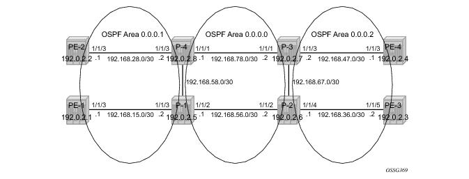
The system addresses and IP interface addresses are configured according to Figure 153. An interior gateway protocol (IGP) is needed to distribute routing information on all PEs. In this case, the IGP is OSPF using the backbone area (area 0.0.0.0) in the core and normal areas (area 0.0.0.1 and area 0.0.0.2) in the two metro regions, connected towards the backbone area via ABRs. A configuration example is shown below for PE-1 and P-1. A similar configuration can be derived for the other P and PE nodes.
A:PE-1# configure router ospf
traffic-engineering
area 0.0.0.1
interface "system"
exit
interface "int-PE-1-P-1"
interface-type point-to-point
exit
exit
A:P-1# configure router ospf
traffic-engineering
area 0.0.0.0
interface "int-P-1-P-2"
interface-type point-to-point
exit
interface "int-P-1-P-4"
interface-type point-to-point
exit
exit
area 0.0.0.1
interface "int-P-1-PE-1"
interface-type point-to-point
exit
exit
Since fast reroute will be enabled on the RSVP LSPs in the core area, traffic engineering is needed on the IGP. By doing this, OSPF will generate opaque LSAs which are collected in a traffic engineering database (TED), separate from the traditional OSPF topology database. OSPF interfaces are setup as type point-to-point to improve convergence, no DR/BDR election process is performed.
1 On all nodes originating/terminating a T-LDP session, an explicit ldp-over-rsvp parameter must be configured to enable this OSPF instance for LDPoRSVP. In the example, this becomes.
A:PE-[1..4]# configure router ospf ldp-over-rsvp
A:P-[1..4]# configure router ospf ldp-over-rsvp
To verify that OSPF neighbors are up (state null, show router ospf neighbor) is performed. To check if IP interface addresses/subnets are known on all PEs,
show router route-table or
show router fib IOM-card-slot will display the content of the forwarding information base (FIB).
A:PE-1# show router ospf neighbor
===============================================================================
OSPF Neighbors
===============================================================================
Interface-Name Rtr Id State Pri RetxQ TTL
-------------------------------------------------------------------------------
int-PE-1-P-1 192.0.2.5 Full 1 0 36
-------------------------------------------------------------------------------
No. of Neighbors: 1
===============================================================================
A:PE-1#
A:PE-1# show router route-table
===============================================================================
Route Table (Router: Base)
===============================================================================
Dest Prefix Type Proto Age Pref
Next Hop[Interface Name] Metric
-------------------------------------------------------------------------------
192.0.2.1/32 Local Local 02h42m42s 0
system 0
192.0.2.2/32 Remote OSPF 02h42m26s 10
192.168.15.2 3000
192.0.2.3/32 Remote OSPF 02h42m26s 10
192.168.15.2 3000
192.0.2.4/32 Remote OSPF 02h41m55s 10
192.168.15.2 4000
192.0.2.5/32 Remote OSPF 02h42m27s 10
192.168.15.2 1000
192.0.2.6/32 Remote OSPF 02h42m26s 10
192.168.15.2 2000
192.0.2.7/32 Remote OSPF 02h42m10s 10
192.168.15.2 3000
192.0.2.8/32 Remote OSPF 02h42m25s 10
192.168.15.2 2000
192.168.15.0/30 Local Local 02h42m32s 0
int-PE-1-P-1 0
192.168.28.0/30 Remote OSPF 02h42m10s 10
192.168.15.2 3000
192.168.36.0/30 Remote OSPF 02h42m26s 10
192.168.15.2 3000
192.168.47.0/30 Remote OSPF 02h42m10s 10
192.168.15.2 4000
192.168.56.0/30 Remote OSPF 02h42m27s 10
192.168.15.2 2000
192.168.58.0/30 Remote OSPF 02h42m27s 10
192.168.15.2 2000
192.168.67.0/30 Remote OSPF 02h42m26s 10
192.168.15.2 3000
192.168.78.0/30 Remote OSPF 02h42m10s 10
192.168.15.2 3000
-------------------------------------------------------------------------------
No. of Routes: 16
===============================================================================
A:PE-1#
A:PE-1# show router fib 1
===============================================================================
FIB Display
===============================================================================
Prefix Protocol
NextHop
-------------------------------------------------------------------------------
192.0.2.1/32 LOCAL
192.0.2.1 (system)
192.0.2.2/32 OSPF
192.168.15.2 (int-PE-1-P-1)
192.0.2.3/32 OSPF
192.168.15.2 (int-PE-1-P-1)
192.0.2.4/32 OSPF
192.168.15.2 (int-PE-1-P-1)
192.0.2.5/32 OSPF
192.168.15.2 (int-PE-1-P-1)
192.0.2.6/32 OSPF
192.168.15.2 (int-PE-1-P-1)
192.0.2.7/32 OSPF
192.168.15.2 (int-PE-1-P-1)
192.0.2.8/32 OSPF
192.168.15.2 (int-PE-1-P-1)
192.168.15.0/30 LOCAL
192.168.15.0 (int-PE-1-P-1)
192.168.28.0/30 OSPF
192.168.15.2 (int-PE-1-P-1)
192.168.36.0/30 OSPF
192.168.15.2 (int-PE-1-P-1)
192.168.47.0/30 OSPF
192.168.15.2 (int-PE-1-P-1)
192.168.56.0/30 OSPF
192.168.15.2 (int-PE-1-P-1)
192.168.58.0/30 OSPF
192.168.15.2 (int-PE-1-P-1)
192.168.67.0/30 OSPF
192.168.15.2 (int-PE-1-P-1)
192.168.78.0/30 OSPF
192.168.15.2 (int-PE-1-P-1)
-------------------------------------------------------------------------------
Total Entries : 16
-------------------------------------------------------------------------------
===============================================================================
A:PE-1#
A:PE-1# configure router mpls no shutdown
A:PE-1# configure router rsvp no shutdown
A:PE-1# configure router mpls
interface "system"
exit
interface "int-PE-1-P-1"
exit
no shutdown
A:PE-1# configure router rsvp
interface "system"
exit
interface "int-PE-1-P-1"
exit
no shutdown
A:PE-1# configure router mpls
...
path "p-pe1-p1"
hop 1 192.168.15.2 strict
no shutdown
exit
path "p-pe1-p1-p4"
hop 1 192.168.15.2 strict
hop 2 192.168.58.2 strict
no shutdown
exit
lsp "LSP-PE-1-P-1"
to 192.0.2.5
primary "p-pe1-p1"
exit
no shutdown
exit
lsp "LSP-PE-1-P-4"
to 192.0.2.8
primary "p-pe1-p1-p4"
exit
no shutdown
exit
no shutdown
A:P-1# configure router mpls
...
path "p-p1-p2"
hop 1 192.168.56.2 strict
no shutdown
exit
path "p-p1-p4"
hop 1 192.168.58.2 strict
no shutdown
exit
path "p-p1-p2-p3"
hop 1 192.168.56.2 strict
hop 2 192.168.67.2 strict
no shutdown
exit
path "p-p1-pe1"
hop 1 192.168.15.1 strict
no shutdown
exit
path "p-p1-p4-pe2"
hop 1 192.168.58.2 strict
hop 2 192.168.28.1 strict
no shutdown
exit
lsp "LSP-P-1-PE-1"
to 192.0.2.1
primary "p-p1-pe1"
exit
no shutdown
exit
lsp "LSP-P-1-PE-2"
to 192.0.2.2
primary "p-p1-p4-pe2"
exit
no shutdown
exit
lsp "LSP-P-1-P-2"
to 192.0.2.6
cspf
fast-reroute facility
exit
primary "p-p1-p2"
exit
no shutdown
exit
lsp "LSP-P-1-P-3"
to 192.0.2.7
cspf
fast-reroute facility
exit
primary "p-p1-p2-p3"
exit
no shutdown
exit
lsp "LSP-P-1-P-4"
to 192.0.2.8
cspf
fast-reroute facility
exit
primary "p-p1-p4"
exit
no shutdown
exit
no shutdown
To display the state of RSVP LSPs, several show commands can be used. A command to show the TTM is show router tunnel-table with parameter
rsvp to reference to RSVP LSP signaling protocol. By default, an RSVP LSP has preference
7.
A:PE-1# show router mpls lsp
===============================================================================
MPLS LSPs (Originating)
===============================================================================
LSP Name To Fastfail Adm Opr
Config
-------------------------------------------------------------------------------
LSP-PE-1-P-1 192.0.2.5 No Up Up
LSP-PE-1-P-4 192.0.2.8 No Up Up
-------------------------------------------------------------------------------
LSPs : 2
===============================================================================
A:PE-1#
A:PE-1# show router tunnel-table
===============================================================================
Tunnel Table (Router: Base)
===============================================================================
Destination Owner Encap TunnelId Pref Nexthop Metric
-------------------------------------------------------------------------------
192.0.2.5/32 rsvp MPLS 1 7 192.168.15.2 65535
192.0.2.8/32 rsvp MPLS 131 7 192.168.15.2 65535
===============================================================================
A:PE-1#
A:P-1# show router mpls lsp
===============================================================================
MPLS LSPs (Originating)
===============================================================================
LSP Name To Fastfail Adm Opr
Config
-------------------------------------------------------------------------------
LSP-P-1-PE-1 192.0.2.1 No Up Up
LSP-P-1-P-2 192.0.2.6 Yes Up Up
LSP-P-1-P-3 192.0.2.7 Yes Up Up
LSP-P-1-P-4 192.0.2.8 Yes Up Up
LSP-P-1-PE-2 192.0.2.2 No Up Up
-------------------------------------------------------------------------------
LSPs : 5
===============================================================================
A:PE-1#
A:P-1# show router tunnel-table
===============================================================================
Tunnel Table (Router: Base)
===============================================================================
Destination Owner Encap TunnelId Pref Nexthop Metric
-------------------------------------------------------------------------------
192.0.2.1/32 rsvp MPLS 1 7 192.168.15.1 65535
192.0.2.2/32 rsvp MPLS 269 7 192.168.58.2 65535
192.0.2.6/32 rsvp MPLS 7 7 192.168.56.2 1000
192.0.2.7/32 rsvp MPLS 11 7 192.168.56.2 2000
192.0.2.8/32 rsvp MPLS 13 7 192.168.58.2 1000
===============================================================================
A:PE-1#
A:P[E]-[1..4]# configure router mpls lsp <lsp-name> metric [0..65535]
A:PE-1# configure router mpls lsp "LSP-PE-1-P-1"
A:PE-1>config>router>mpls>lsp# info detail
to 192.0.2.5
...
ldp-over-rsvp include
...
A:PE-1# show router mpls lsp LSP-PE-1-P-1 detail
===============================================================================
MPLS LSPs (Originating) (Detail)
===============================================================================
-------------------------------------------------------------------------------
Type : Originating
-------------------------------------------------------------------------------
LSP Name : LSP-PE-1-P-1 LSP Tunnel ID : 1
From : 192.0.2.1 To : 192.0.2.5
Adm State : Up Oper State : Up
...
LdpOverRsvp : Enabled VprnAutoBind : Enabled
...
===============================================================================
A:PE-1#
A:PE-1# configure router mpls lsp <LSP-name> ldp-over-rsvp exclude
A:PE-1# configure router ldp
=============================================================================
targeted-session
peer 192.0.2.5
exit
peer 192.0.2.8
exit
exit
=============================================================================
A:PE-1#
A:PE-1# show router ldp session
=============================================================================
LDP Sessions
=============================================================================
Peer LDP Id Adj Type State Msg Sent Msg Recv Up Time
-----------------------------------------------------------------------------
192.0.2.5:0 Targeted Established 3216 3217 0d 04:53:52
192.0.2.8:0 Targeted Established 3220 3222 0d 04:53:54
-----------------------------------------------------------------------------
No. of Sessions: 2
=============================================================================
A:PE-1#
A:PE-1# configure router ldp
=============================================================================
targeted-session
peer 192.0.2.5
tunneling
exit
exit
peer 192.0.2.8
tunneling
exit
exit
exit
=============================================================================
A:PE-1#
As a result of the tunneling command, LDPoRSVP process (FEC resolving) is initiated. As already stated in the introduction, FEC resolution is a three-step process. First run an SPF calculation to the destination, then select an endpoint(s) as close to that destination followed by a tunnel(s) to that endpoint. The next two steps go more into detail on this FEC resolution process. Step 5 will handle inter-area FEC resolving and Step 6 will handle intra-area FEC resolving.
A:PE-1# show router ldp bindings prefix 192.0.2.3/32 active
===============================================================================
Legend: (S) - Static
===============================================================================
LDP Prefix Bindings (Active)
===============================================================================
Prefix Op IngLbl EgrLbl EgrIntf/LspId EgrNextHop
-------------------------------------------------------------------------------
192.0.2.3/32 Push -- 131060 LspId 1 192.0.2.5
192.0.2.3/32 Swap 131063 131060 LspId 1 192.0.2.5
-------------------------------------------------------------------------------
No. of Prefix Bindings: 2
===============================================================================
A:PE-1#
A:PE-1# show router mpls lsp detail
===============================================================================
MPLS LSPs (Originating) (Detail)
===============================================================================
-------------------------------------------------------------------------------
Type : Originating
-------------------------------------------------------------------------------
LSP Name : LSP-PE-1-P-1 LSP Tunnel ID : 1
...
===============================================================================
A:PE-1#
A:PE-1# show router tunnel-table
===============================================================================
Tunnel Table (Router: Base)
===============================================================================
Destination Owner Encap TunnelId Pref Nexthop Metric
-------------------------------------------------------------------------------
...
192.0.2.5/32 rsvp MPLS 1 7 192.168.15.2 65535
...
===============================================================================
A:PE-1#
A:P-1# show router ldp bindings prefix 192.0.2.3/32 active
===============================================================================
Legend: (S) - Static
===============================================================================
LDP Prefix Bindings (Active)
===============================================================================
Prefix Op IngLbl EgrLbl EgrIntf/LspId EgrNextHop
-------------------------------------------------------------------------------
192.0.2.3/32 Push -- 131070 LspId 7 192.0.2.6
192.0.2.3/32 Swap 131060 131070 LspId 7 192.0.2.6
-------------------------------------------------------------------------------
No. of Prefix Bindings: 2
===============================================================================
A:P-1#
A:P-1# show router mpls lsp detail
===============================================================================
MPLS LSPs (Originating) (Detail)
===============================================================================
...
-------------------------------------------------------------------------------
Type : Originating
-------------------------------------------------------------------------------
LSP Name : LSP-P-1-P-2 LSP Tunnel ID : 7
...
===============================================================================
A:P-1#
A:P-1# show router tunnel-table
===============================================================================
Tunnel Table (Router: Base)
===============================================================================
Destination Owner Encap TunnelId Pref Nexthop Metric
-------------------------------------------------------------------------------
...
192.0.2.6/32 rsvp MPLS 7 7 192.168.56.2 1000
...
===============================================================================
A:P-1#
A:P-2# show router ldp bindings prefix 192.0.2.3/32 active
===============================================================================
Legend: (S) - Static
===============================================================================
LDP Prefix Bindings (Active)
===============================================================================
Prefix Op IngLbl EgrLbl EgrIntf/LspId EgrNextHop
-------------------------------------------------------------------------------
192.0.2.3/32 Push -- 131071 LspId 5 192.0.2.3
192.0.2.3/32 Swap 131070 131071 LspId 5 192.0.2.3
-------------------------------------------------------------------------------
No. of Prefix Bindings: 2
===============================================================================
A:P-2#
A:P-2# show router mpls lsp detail
...
-------------------------------------------------------------------------------
Type : Originating
-------------------------------------------------------------------------------
LSP Name : LSP-P-2-PE-3 LSP Tunnel ID : 5
...
A:P-2# show router tunnel-table
===============================================================================
Tunnel Table (Router: Base)
===============================================================================
Destination Owner Encap TunnelId Pref Nexthop Metric
-------------------------------------------------------------------------------
...
192.0.2.3/32 rsvp MPLS 5 7 192.168.36.2 65535
...
===============================================================================
A:P-2#
When the endpoints are defined, one corresponding RSVP LSP to those endpoints will be chosen (when ECMP=1). Selection criteria are as follows. When RSVP LSPs are configured under the T-LDP tunneling command (maximum 4), the one with the lowest LSP metric will be selected. When no RSVP LSPs are configured under the T-LDP
tunneling command, LDP checks TTM for all available RSVP LSPs. The RSVP LSP with the least metric and operational state up will be selected.
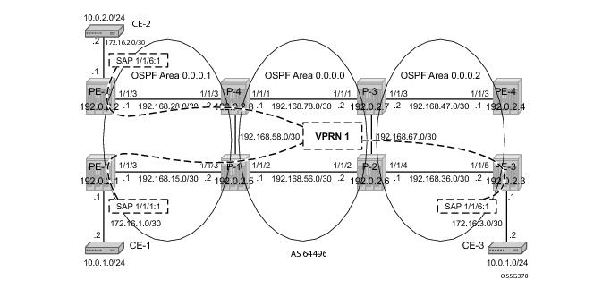
A:PE-1# configure service vprn 1
autonomous-system 64496
route-distinguisher 64496:1
auto-bind ldp
vrf-target target:64496:1
interface "towards-CE-1" create
address 172.16.1.1/30
sap 1/1/1:1 create
exit
exit
static-route 10.0.1.0/24 next-hop 172.16.1.2
no shutdown
A:PE-1# configure router bgp
group "internal"
family ipv4 vpn-ipv4
type internal
neighbor 192.0.2.5
exit
exit
no shutdown
A:P-1# configure router bgp
group "internal"
family ipv4 vpn-ipv4
type internal
cluster 1.1.1.1
neighbor 192.0.2.1
exit
neighbor 192.0.2.2
exit
neighbor 192.0.2.3
exit
exit
A:PE-1# show router rsvp session lsp-name LSP-PE-1-P-1::p-pe1-p1 detail
===============================================================================
RSVP Sessions (Detailed)
===============================================================================
-------------------------------------------------------------------------------
LSP : LSP-PE-1-P-1::p-pe1-p1
-------------------------------------------------------------------------------
From : 192.0.2.1 To : 192.0.2.5
Tunnel ID : 1 LSP ID : 1536
Style : SE State : Up
Session Type : Originate
In Interface : n/a Out Interface : 1/1/3
In Label : n/a Out Label : 131064
Previous Hop : n/a Next Hop : 192.168.15.2
...
===============================================================================
A:PE-1#
A:PE-1# show router ldp bindings prefix 192.0.2.3/32 active
===============================================================================
Legend: (S) - Static
===============================================================================
LDP Prefix Bindings (Active)
===============================================================================
Prefix Op IngLbl EgrLbl EgrIntf/LspId EgrNextHop
-------------------------------------------------------------------------------
192.0.2.3/32 Push -- 131060 LspId 1 192.0.2.5
192.0.2.3/32 Swap 131063 131060 LspId 1 192.0.2.5
-------------------------------------------------------------------------------
No. of Prefix Bindings: 2
===============================================================================
A:PE-1#
Service label 131070
2 is added as the inner MP-BGP label on each user packet
A:PE-1# show router bgp neighbor 192.0.2.5 received-routes vpn-ipv4
===============================================================================
BGP Router ID:192.0.2.1 AS:64496 Local AS:64496
===============================================================================
Legend -
Status codes : u - used, s - suppressed, h - history, d - decayed, * - valid
Origin codes : i - IGP, e - EGP, ? - incomplete, > - best
===============================================================================
BGP VPN-IPv4 Routes
===============================================================================
Flag Network LocalPref MED
Nexthop VPNLabel
As-Path
-------------------------------------------------------------------------------
...
u*>i 64496:1:172.16.3.0/30 100 None
192.0.2.3 131070
No As-Path
===============================================================================
A:PE-1#
A:P-1# show router rsvp session lsp-name LSP-P-1-P-2::p-p1-p2 detail
===============================================================================
RSVP Sessions (Detailed)
===============================================================================
-------------------------------------------------------------------------------
LSP : LSP-P-1-P-2::p-p1-p2
-------------------------------------------------------------------------------
From : 192.0.2.5 To : 192.0.2.6
Tunnel ID : 7 LSP ID : 48128
Style : SE State : Up
Session Type : Originate
In Interface : n/a Out Interface : 1/1/2
In Label : n/a Out Label : 131062
Previous Hop : n/a Next Hop : 192.168.56.2
...
===============================================================================
A:PE-1#
A:P-1# show router ldp bindings prefix 192.0.2.3/32 active
===============================================================================
Legend: (S) - Static
===============================================================================
LDP Prefix Bindings (Active)
===============================================================================
Prefix Op IngLbl EgrLbl EgrIntf/LspId EgrNextHop
-------------------------------------------------------------------------------
192.0.2.3/32 Push -- 131070 LspId 7 192.0.2.6
192.0.2.3/32 Swap 131060 131070 LspId 7 192.0.2.6
-------------------------------------------------------------------------------
No. of Prefix Bindings: 2
===============================================================================
A:P-1#
A:P-2# show router rsvp session lsp-name LSP-P-2-PE-3::p-p2-pe3 detail
===============================================================================
RSVP Sessions (Detailed)
===============================================================================
LSP : LSP-P-2-PE-3::p-p2-pe3
-------------------------------------------------------------------------------
From : 192.0.2.6 To : 192.0.2.3
Tunnel ID : 5 LSP ID : 54272
Style : SE State : Up
Session Type : Originate
In Interface : n/a Out Interface : 1/1/4
In Label : n/a Out Label : 131066
...
===============================================================================
A:P-2#
A:P-2# show router ldp bindings prefix 192.0.2.3/32 active
===============================================================================
Legend: (S) - Static
===============================================================================
LDP Prefix Bindings (Active)
===============================================================================
Prefix Op IngLbl EgrLbl EgrIntf/LspId EgrNextHop
-------------------------------------------------------------------------------
192.0.2.3/32 Push -- 131071 LspId 5 192.0.2.3
192.0.2.3/32 Swap 131070 131071 LspId 5 192.0.2.3
-------------------------------------------------------------------------------
No. of Prefix Bindings: 2
===============================================================================
A:P-2#
A:PE-1# show router ldp bindings prefix 192.0.2.2/32 active
===============================================================================
Legend: (S) - Static
===============================================================================
LDP Prefix Bindings (Active)
===============================================================================
Prefix Op IngLbl EgrLbl EgrIntf/LspId EgrNextHop
-------------------------------------------------------------------------------
192.0.2.2/32 Push -- 131066 LspId 1 192.0.2.5
192.0.2.2/32 Swap 131064 131066 LspId 1 192.0.2.5
-------------------------------------------------------------------------------
No. of Prefix Bindings: 2
===============================================================================
A:PE-1#
A:PE-1# show router mpls lsp detail
===============================================================================
MPLS LSPs (Originating) (Detail)
===============================================================================
-------------------------------------------------------------------------------
Type : Originating
-------------------------------------------------------------------------------
LSP Name : LSP-PE-1-P-1 LSP Tunnel ID : 1
...
===============================================================================
A:PE-1#
A:PE-1# show router tunnel-table
===============================================================================
Tunnel Table (Router: Base)
===============================================================================
Destination Owner Encap TunnelId Pref Nexthop Metric
-------------------------------------------------------------------------------
...
192.0.2.5/32 rsvp MPLS 1 7 192.168.15.2 65535
...
===============================================================================
A:PE-1#
A:P-1# show router ldp bindings prefix 192.0.2.2/32 active
===============================================================================
Legend: (S) - Static
===============================================================================
LDP Prefix Bindings (Active)
==============================================================================
Prefix Op IngLbl EgrLbl EgrIntf/LspId EgrNextHop
-------------------------------------------------------------------------------
192.0.2.2/32 Push -- 131071 LspId 269 192.0.2.2
192.0.2.2/32 Swap 131066 131071 LspId 269 192.0.2.2
-------------------------------------------------------------------------------
No. of Prefix Bindings: 2
===============================================================================
A:PE-1#
A:PE-1# show router mpls lsp detail
===============================================================================
MPLS LSPs (Originating) (Detail)
===============================================================================
...
-------------------------------------------------------------------------------
Type : Originating
-------------------------------------------------------------------------------
LSP Name : LSP-P-1-PE-2 LSP Tunnel ID : 269
...
===============================================================================
A:PE-1#
A:P-1# show router tunnel-table
===============================================================================
Tunnel Table (Router: Base)
===============================================================================
Destination Owner Encap TunnelId Pref Nexthop Metric
-------------------------------------------------------------------------------
...
192.0.2.2/32 rsvp MPLS 269 7 192.168.58.2 65535
...
===============================================================================
A:PE-1#
When the endpoint node (P-1) is defined, the corresponding RSVP LSP to this endpoint will be chosen. Selection criteria are as follows (when ECMP=1). When RSVP LSPs are configured under the T-LDP tunneling command (maximum 4), the one with the lowest LSP metric will be selected. When no RSVP LSPs are configured under the T-LDP
tunneling command, LDP checks TTM for all available RSVP LSPs. The RSVP LSP with the least metric and operational state
up will be selected.
A:PE-1# show router rsvp session lsp-name LSP-PE-1-P-1::p-pe1-p1 detail
===============================================================================
RSVP Sessions (Detailed)
===============================================================================
LSP : LSP-PE-1-P-1::p-pe1-p1
-------------------------------------------------------------------------------
From : 192.0.2.1 To : 192.0.2.5
Tunnel ID : 1 LSP ID : 1536
Style : SE State : Up
Session Type : Originate
In Interface : n/a Out Interface : 1/1/3
In Label : n/a Out Label : 131064
Previous Hop : n/a Next Hop : 192.168.15.2
...
===============================================================================
A:PE-1#
A:PE-1# show router ldp bindings prefix 192.0.2.2/32 active
===============================================================================
Legend: (S) - Static
===============================================================================
LDP Prefix Bindings (Active)
===============================================================================
Prefix Op IngLbl EgrLbl EgrIntf/LspId EgrNextHop
-------------------------------------------------------------------------------
192.0.2.2/32 Push -- 131066 LspId 1 192.0.2.5
192.0.2.2/32 Swap 131064 131066 LspId 1 192.0.2.5
-------------------------------------------------------------------------------
No. of Prefix Bindings: 2
===============================================================================
A:PE-1#
Service label 131070 is added as the inner MP-BGP label on each user packet
3.
A:PE-1# show router bgp neighbor 192.0.2.5 received-routes vpn-ipv4
===============================================================================
BGP Router ID:192.0.2.1 AS:64496 Local AS:64496
===============================================================================
Legend -
Status codes : u - used, s - suppressed, h - history, d - decayed, * - valid
Origin codes : i - IGP, e - EGP, ? - incomplete, > - best
===============================================================================
BGP VPN-IPv4 Routes
===============================================================================
Flag Network LocalPref MED
Nexthop VPNLabel
As-Path
-------------------------------------------------------------------------------
u*>i 64496:1:10.0.2.0/24 100 None
192.0.2.2 131070
No As-Path
�
No As-Path
u*>i 64496:1:172.16.2.0/30 100 None
192.0.2.2 131070
No As-Path
...
-------------------------------------------------------------------------------
Routes : 4
===============================================================================
A:PE-1#
A:P-1# show router mpls lsp LSP-P-1-PE-2 path detail4
===============================================================================
MPLS LSP LSP-P-1-PE-2 Path (Detail)
===============================================================================
Legend :
@ - Detour Available # - Detour In Use
b - Bandwidth Protected n - Node Protected
s - Soft Preemption
===============================================================================
-------------------------------------------------------------------------------
LSP LSP-P-1-PE-2 Path p-p1-p4-pe2
-------------------------------------------------------------------------------
LSP Name : LSP-P-1-PE-2 Path LSP ID : 6144
From : 192.0.2.5 To : 192.0.2.2
Adm State : Up Oper State : Up
Path Name : p-p1-p4-pe2 Path Type : Primary
Path Admin : Up Path Oper : Up
OutInterface: 1/1/4 Out Label : 131057
ExplicitHops:
192.168.58.2 -> 192.168.28.1
Actual Hops :
192.168.58.1(192.0.2.5) Record Label : N/A
-> 192.168.58.2(192.0.2.8) Record Label : 131057
-> 192.168.28.1 Record Label : 131064
...
===============================================================================
A:PE-1#
A:P-1# show router ldp bindings prefix 192.0.2.2/32 active
===============================================================================
Legend: (S) - Static
===============================================================================
LDP Prefix Bindings (Active)
===============================================================================
Prefix Op IngLbl EgrLbl EgrIntf/LspId EgrNextHop
-------------------------------------------------------------------------------
192.0.2.2/32 Push -- 131071 LspId 269 192.0.2.2
192.0.2.2/32 Swap 131066 131071 LspId 269 192.0.2.2
-------------------------------------------------------------------------------
No. of Prefix Bindings: 2
===============================================================================
A:PE-1#
Command: prefer-tunnel-in-tunnel
Until now in this example, no RSVP LSPs are configured inside the ldp targeted-session peer tunneling context. Therefore, two additional strict non-cspf RSVP LSPs are added between ingress LER PE-1 node and egress LER P-1 node. Both LSPs will have an explicit metric setting and will be applied inside the
ldp tunneling context. On the Layer 3 interface between PE-1 and P-1 node, iLDP is enabled.
A:PE-1# configure router ldp
interface-parameters
interface "int-PE-1-P-1"
exit
exit
A:P-1# configure router ldp
interface-parameters
interface "int-P-1-PE-1"
exit
exit
A:PE-1# configure router mpls
...
path "p-pe1-p1"
hop 1 192.168.15.2 strict
no shutdown
exit
...
lsp "LSP-PE-1-P-1-metric100"
to 192.0.2.5
metric 100
primary "p-pe1-p1"
exit
exit
lsp "LSP-PE-1-P-1-metric200"
to 192.0.2.5
metric 200
primary "p-pe1-p1"
exit
exit
no shutdown
A:PE-1# configure router ldp
...
targeted-session
peer 192.0.2.5
tunneling
lsp "LSP-PE-1-P-1-metric100"
lsp "LSP-PE-1-P-1-metric200"
exit
exit
...
exit
A:PE-1# show router tunnel-table
===============================================================================
Tunnel Table (Router: Base)
===============================================================================
Destination Owner Encap TunnelId Pref Nexthop Metric
-------------------------------------------------------------------------------
192.0.2.5/32 rsvp MPLS 1 7 192.168.15.2 65535
192.0.2.5/32 rsvp MPLS 2 7 192.168.15.2 100
192.0.2.5/32 rsvp MPLS 3 7 192.168.15.2 200
192.0.2.5/32 ldp MPLS - 9 192.168.15.2 1000
...
===============================================================================
A:PE-1#
A:PE-1# show router ldp bindings prefix 192.0.2.5/32 active
===============================================================================
Legend: (S) - Static
===============================================================================
LDP Prefix Bindings (Active)
===============================================================================
Prefix Op IngLbl EgrLbl EgrIntf/LspId EgrNextHop
-------------------------------------------------------------------------------
192.0.2.5/32 Push -- 131071 1/1/3 192.168.15.2
192.0.2.5/32 Swap 131067 131071 1/1/3 192.168.15.2
-------------------------------------------------------------------------------
No. of Prefix Bindings: 2
===============================================================================
A:PE-1#
This behavior can be changed by setting the prefer-tunnel-in-tunnel command in the LDP context. Now, the LDPoRSVP tunnel with the best (= lowest) metric is taken.
A:PE-1# configure router ldp prefer-tunnel-in-tunnel
A:PE-1# show router ldp bindings prefix 192.0.2.5/32 active
===============================================================================
Legend: (S) - Static
===============================================================================
LDP Prefix Bindings (Active)
===============================================================================
Prefix Op IngLbl EgrLbl EgrIntf/LspId EgrNextHop
-------------------------------------------------------------------------------
192.0.2.5/32 Push -- 131071 LspId 2 192.0.2.5
192.0.2.5/32 Swap 131067 131071 LspId 2 192.0.2.5
-------------------------------------------------------------------------------
No. of Prefix Bindings: 2
===============================================================================
A:PE-1#
A:PE-1# show router mpls lsp detail
===============================================================================
MPLS LSPs (Originating) (Detail)
===============================================================================
-------------------------------------------------------------------------------
Type : Originating
-------------------------------------------------------------------------------
LSP Name : LSP-PE-1-P-1-metric100 LSP Tunnel ID : 2
...
===============================================================================
A:PE-1#
A:PE-1# configure router mpls lsp LSP-PE-1-P-1-metric100 shutdown
A:PE-1# show router ldp bindings prefix 192.0.2.5/32 active
===============================================================================
Legend: (S) - Static
===============================================================================
LDP Prefix Bindings (Active)
===============================================================================
Prefix Op IngLbl EgrLbl EgrIntf/LspId EgrNextHop
-------------------------------------------------------------------------------
192.0.2.5/32 Push -- 131071 LspId 3 192.0.2.5
192.0.2.5/32 Swap 131067 131071 LspId 3 192.0.2.5
-------------------------------------------------------------------------------
No. of Prefix Bindings: 2
===============================================================================
A:PE-1#
A:PE-1# show router mpls lsp detail
===============================================================================
MPLS LSPs (Originating) (Detail)
===============================================================================
-------------------------------------------------------------------------------
Type : Originating
-------------------------------------------------------------------------------
LSP Name : LSP-PE-1-P-1-metric200 LSP Tunnel ID : 3
...
===============================================================================
A:PE-1#
A:PE-1# configure router mpls lsp LSP-PE-1-P-1-metric200 shutdown
A:PE-1# show router ldp bindings prefix 192.0.2.5/32 active
===============================================================================
Legend: (S) - Static
===============================================================================
LDP Prefix Bindings (Active)
===============================================================================
Prefix Op IngLbl EgrLbl EgrIntf/LspId EgrNextHop
-------------------------------------------------------------------------------
192.0.2.5/32 Push -- 131071 1/1/3 192.168.15.2
192.0.2.5/32 Swap 131067 131071 1/1/3 192.168.15.2
-------------------------------------------------------------------------------
No. of Prefix Bindings: 2
===============================================================================
A:PE-1#
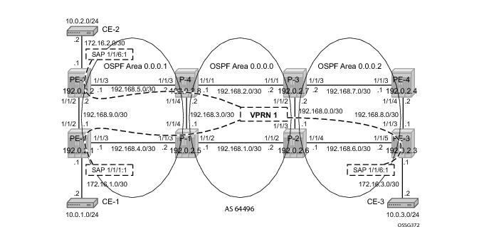
Refer to Figure 155. In the two metro areas, both of the intra PEs are physically connected with each other. Compared with the previous figures, PE-1 node is directly connected to PE-2 and PE-3 node is directly connected to PE-4 (up to the OSPF level).
A:PE-1# configure router interface int-PE-1-PE-2
address 192.168.12.1/30
port 1/1/2
A:PE-2# configure router interface int-PE-1-PE-2
address 192.168.12.2/30
port 1/1/2
A:PE-1# configure router ospf
...
area 0.0.0.1
...
interface "int-PE-1-PE-2"
interface-type point-to-point
exit
exit
A:PE-2# configure router ospf
...
area 0.0.0.1
...
interface "int-PE-2-PE-1"
interface-type point-to-point
exit
exit
A:PE-1# configure router ldp
interface-parameters
interface "int-PE-1-PE-2"
exit
exit
A:PE-2# configure router ldp
interface-parameters
interface "int-PE-2-PE-1"
exit
exit
A:PE-1# show router tunnel-table 192.0.2.2/32
===============================================================================
Tunnel Table (Router: Base)
===============================================================================
Destination Owner Encap TunnelId Pref Nexthop Metric
-------------------------------------------------------------------------------
192.0.2.2/32 ldp MPLS - 9 192.168.12.2 1000
===============================================================================
A:PE-1#
A:PE-1# show router ldp bindings prefix 192.0.2.2/32 active
===============================================================================
Legend: (S) - Static
===============================================================================
LDP Prefix Bindings (Active)
===============================================================================
Prefix Op IngLbl EgrLbl EgrIntf/LspId EgrNextHop
-------------------------------------------------------------------------------
192.0.2.2/32 Push -- 131071 1/1/2 192.168.12.2
192.0.2.2/32 Swap 131063 131071 1/1/2 192.168.12.2
-------------------------------------------------------------------------------
No. of Prefix Bindings: 2
===============================================================================
A:PE-1#
A:PE-1# show router bgp neighbor 192.0.2.5 received-routes vpn-ipv4
===============================================================================
BGP Router ID:192.0.2.1 AS:64496 Local AS:64496
===============================================================================
Legend -
Status codes : u - used, s - suppressed, h - history, d - decayed, * - valid
Origin codes : i - IGP, e - EGP, ? - incomplete, > - best
===============================================================================
BGP VPN-IPv4 Routes
===============================================================================
Flag Network LocalPref MED
Nexthop VPNLabel
As-Path
-------------------------------------------------------------------------------
u*>i 64496:1:10.0.2.0/24 100 None
192.0.2.2 131070
No As-Path
...
u*>i 64496:1:172.16.2.0/30 100 None
192.0.2.2 131070
No As-Path
===============================================================================
A:PE-1#
This label will not change at endpoint node (P-1). Ingress LER (PE-1) will push the service label to the user packet while the egress LER (PE-2) will pop the service label.
show router rsvp session lsp-name LSP-P-1-PE-2::p-p1-p4-pe2 detail cannot be used since it only shows the outgoing RSVP label towards P-4 node. On P-4 node, RSVP transport label 131057 will be swapped into RSVP transport label 131064 for the link P-4 <=> PE-2.