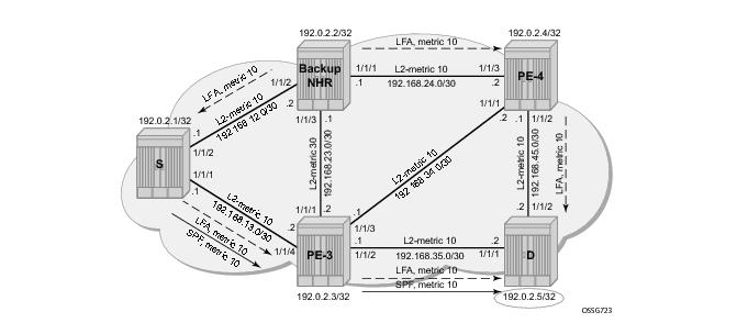
Inequality 1: [SP(backup NHR, D) < {SP(backup NHR, S) + SP(S, D)}]
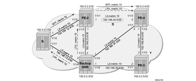
Inequality 3: [SP(backup NHR, D) < {SP(backup NHR, PN) + SP(PN, D)}]
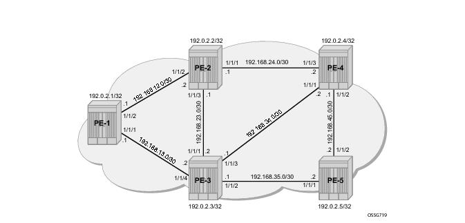
The system addresses and IP interface addresses are configured according to Figure 156. An interior gateway protocol (IGP) is needed to distribute routing information on all PEs. In our case, the IGP is IS-IS where each PE is acting as a Level 2 router. A configuration example is shown for PE-1. Similar configurations can be derived for the other PEs.
*A:PE-1# configure router isis
level-capability level-2
level 2
wide-metrics-only
exit
interface "system"
exit
interface "int-PE-1-PE-2"
interface-type point-to-point
exit
interface "int-PE-1-PE-3"
interface-type point-to-point
exit
no shutdown
IS-IS interfaces are setup as type point-to-point to improve convergence since no DR/BDR election process is done. To verify that IS-IS adjacencies are up, show router isis adjacency is performed. To check if IP interface addresses/subnets are known on all PEs,
show router route-table or
show router fib slot-number will display the content of the forwarding information base (FIB).
*A:PE-1# show router isis adjacency
===============================================================================
ISIS Adjacency
===============================================================================
System ID Usage State Hold Interface MT-ID
-------------------------------------------------------------------------------
PE-2 L2 Up 21 int-PE-1-PE-2 0
PE-3 L2 Up 20 int-PE-1-PE-3 0
-------------------------------------------------------------------------------
Adjacencies : 2
===============================================================================
*A:PE-1#
*A:PE-1# show router route-table
===============================================================================
Route Table (Router: Base)
===============================================================================
Dest Prefix[Flags] Type Proto Age Pref
Next Hop[Interface Name] Metric
-------------------------------------------------------------------------------
192.0.2.1/32 Local Local 07d23h34m 0
system 0
192.0.2.2/32 Remote ISIS 07d23h34m 18
192.168.12.2 10
192.0.2.3/32 Remote ISIS 07d23h17m 18
192.168.13.2 10
192.0.2.4/32 Remote ISIS 07d22h58m 18
192.168.12.2 20
192.0.2.5/32 Remote ISIS 07d23h17m 18
192.168.13.2 20
192.168.12.0/30 Local Local 07d23h34m 0
int-PE-1-PE-2 0
192.168.13.0/30 Local Local 07d23h34m 0
int-PE-1-PE-3 0
192.168.23.0/30 Remote ISIS 07d23h16m 18
192.168.12.2 20
192.168.24.0/30 Remote ISIS 07d23h34m 18
192.168.12.2 20
192.168.34.0/30 Remote ISIS 07d23h17m 18
192.168.13.2 20
192.168.35.0/30 Remote ISIS 07d23h17m 18
192.168.13.2 20
192.168.45.0/30 Remote ISIS 03h59m10s 18
192.168.12.2 30
-------------------------------------------------------------------------------
No. of Routes: 12
Flags: n = Number of times nexthop is repeated
B = BGP backup route available
L = LFA nexthop available
S = Sticky ECMP requested
===============================================================================
*A:PE-1#
*A:PE-1# show router fib 1
===============================================================================
FIB Display
===============================================================================
Prefix [Flags] Protocol
NextHop
-------------------------------------------------------------------------------
192.0.2.1/32 LOCAL
192.0.2.1 (system)
192.0.2.2/32 ISIS
192.168.12.2 (int-PE-1-PE-2)
192.0.2.3/32 ISIS
192.168.13.2 (int-PE-1-PE-3)
192.0.2.4/32 ISIS
192.168.12.2 (int-PE-1-PE-2)
192.0.2.5/32 ISIS
192.168.13.2 (int-PE-1-PE-3)
192.168.12.0/30 LOCAL
192.168.12.0 (int-PE-1-PE-2)
192.168.13.0/30 LOCAL
192.168.13.0 (int-PE-1-PE-3)
192.168.23.0/30 ISIS
192.168.12.2 (int-PE-1-PE-2)
192.168.24.0/30 ISIS
192.168.12.2 (int-PE-1-PE-2)
192.168.34.0/30 ISIS
192.168.13.2 (int-PE-1-PE-3)
192.168.35.0/30 ISIS
192.168.13.2 (int-PE-1-PE-3)
192.168.45.0/30 ISIS
192.168.12.2 (int-PE-1-PE-2)
-------------------------------------------------------------------------------
Total Entries : 12
-------------------------------------------------------------------------------
===============================================================================
*A:PE-1#
*A:PE-1# show router isis status | match "L2 Default Metric"
L2 Default Metric : 10
*A:PE-1#
*A:PE-1# configure router ldp
interface-parameters
interface "int-PE-1-PE-2"
exit
interface "int-PE-1-PE-3"
exit
exit
targeted-session
exit
*A:PE-1# show router tunnel-table
===============================================================================
Tunnel Table (Router: Base)
===============================================================================
Destination Owner Encap TunnelId Pref Nexthop Metric
-------------------------------------------------------------------------------
192.0.2.2/32 ldp MPLS - 9 192.168.12.2 10
192.0.2.3/32 ldp MPLS - 9 192.168.13.2 10
192.0.2.4/32 ldp MPLS - 9 192.168.12.2 20
192.0.2.5/32 ldp MPLS - 9 192.168.13.2 20
-------------------------------------------------------------------------------
Flags: B = BGP backup route available
E = inactive best-external BGP route
===============================================================================
*A:PE-1#
*A:PE-1# configure router isis loopfree-alternate
*A:PE-1# show router isis status | match Loopfree
Loopfree-Alternate : Enabled
*A:PE-1#
*A:PE-1# configure router ldp fast-reroute
*A:PE-1# show router ldp status | match FRR
FRR : Enabled Mcast Upstream FRR : Disabled
*A:PE-1#
|
•
|
The show router isis statistics command displays the number of LFA runs on a specific node.
|
|
•
|
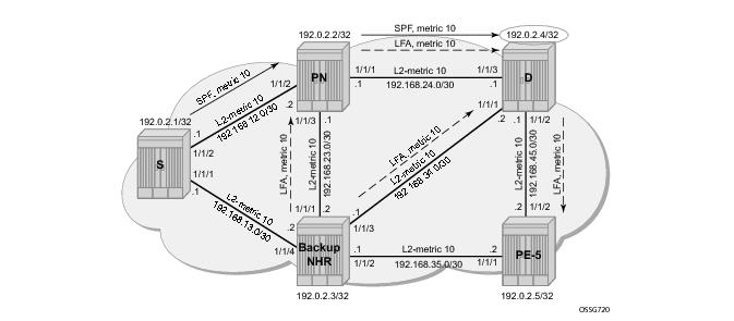
The show router isis lfa-coverage command performs a mathematical calculation between the number of nodes and IPv4/IPv6 routes in the network versus present LFA next-hop protections. In our network (see Figure 156), all IS-IS links have a default Level 2 metric of 10. This results in all four nodes and all IS-IS routes learned by PE1 being 100% LFA protected (link or node). Refer to the following output.
|
|
•
|
The show router isis spf-log command lists the SPF events indicating tye type (Lfa or Reg).
|
|
•
|
The show router route-table command adds an ‘L’ flag as reference that the associated prefix is having also an LFA next-hop available. For detailed interface address information used by the LFA calculation use the show router route-table alternative or show router isis alternative command. The output on PE-1 for PE-4 will look like this:
|
|
•
|
The show router ldp bindings command displays the Label Information Base (LIB). A BU flag is present in case the associated label is used as backup NHLFE for the given prefix 1. As an example, a display on PE-1 for prefix PE-4 will look like this:
|
|
•
|
The show router ldp bindings active command displays the Label Forwarding Information Base (LFIB). Also the BU flag is present and in addition a reference to the label action itself: pop for eLER, push for iLER and swap for LSR.
|
*A:PE-1# configure router interface "int-PE-1-PE-2" ldp-sync-timer 10
*A:PE-1# configure router interface "int-PE-1-PE-3" ldp-sync-timer 10
When this timer is enabled, it means that when an interface is restored again, the IGP will advertise this link in the network with an infinite metric. The ldp-sync-timer is started, LDP adjacencies are brought up together with a label exchange. After the
ldp-sync-timer expires, the normal metric is advertised in the network again.
*A:PE-1# configure service sdp 5
far-end 192.0.2.5
ldp
keep-alive
shutdown
exit
no shutdown
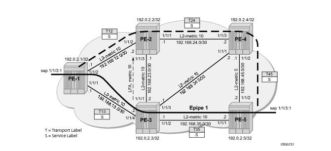
*A:PE-1# configure service epipe 1
service-mtu 1450
sap 1/1/3:1 create
exit
spoke-sdp 5:1 create
no shutdown
exit
no shutdown
*A:PE-4# configure router isis interface int-PE-4-PE-5 level 2 metric 5
*A:PE-5# configure router isis interface int-PE-5-PE-4 level 2 metric 5
*A:PE-1# show router isis routes alternative 192.0.2.5
===============================================================================
Route Table
===============================================================================
Prefix[Flags] Metric Lvl/Typ Ver. SysID/Hostname
NextHop MT AdminTag
Alt-Nexthop Alt- Alt-Type
Metric
-------------------------------------------------------------------------------
192.0.2.5/32 20 2/Int. 20 PE-3
192.168.13.2 0 0
192.168.12.2(L) 25 NP
-------------------------------------------------------------------------------
No. of Routes: 1
Flags: L = Loop-Free Alternate nexthop
Legend: LP = linkProtection, NP = nodeProtection
===============================================================================
*A:PE-1#
*A:PE-1# show router ldp bindings service-id 1
===============================================================================
LDP LSR ID: 192.0.2.1
===============================================================================
Legend: U - Label In Use, N - Label Not In Use, W - Label Withdrawn
S - Status Signaled Up, D - Status Signaled Down
E - Epipe Service, V - VPLS Service, M - Mirror Service
A - Apipe Service, F - Fpipe Service, I - IES Service, R - VPRN service
P - Ipipe Service, WP - Label Withdraw Pending, C - Cpipe Service
BU - Alternate For Fast Re-Route, TLV - (Type, Length: Value)
===============================================================================
LDP Service FEC 128 Bindings
===============================================================================
Type VCId SvcId SDPId Peer IngLbl EgrLbl LMTU RMTU
-------------------------------------------------------------------------------
E-Eth 1 1 5 192.0.2.5 131066U 131066S 1436 1436
-------------------------------------------------------------------------------
No. of VC Labels: 1
<snipped>
*A:PE-1#
*A:PE-1# show router ldp bindings active prefix 192.0.2.5/32
===============================================================================
Legend: (S) - Static (M) - Multi-homed Secondary Support
(B) - BGP Next Hop (BU) - Alternate Next-hop for Fast Re-Route
===============================================================================
LDP Prefix Bindings (Active)
===============================================================================
Prefix Op IngLbl EgrLbl EgrIntf/LspId EgrNextHop
-------------------------------------------------------------------------------
192.0.2.5/32 Push -- 131067 1/1/1 192.168.13.2
192.0.2.5/32 Push -- 131067BU 1/1/2 192.168.12.2
192.0.2.5/32 Swap 131067 131067 1/1/1 192.168.13.2
192.0.2.5/32 Swap 131067 131067BU 1/1/2 192.168.12.2
-------------------------------------------------------------------------------
No. of Prefix Active Bindings: 4
===============================================================================
*A:PE-1#
*A:PE-3# show router ldp bindings active prefix 192.0.2.5/32
===============================================================================
Legend: (S) - Static (M) - Multi-homed Secondary Support
(B) - BGP Next Hop (BU) - Alternate Next-hop for Fast Re-Route
===============================================================================
LDP Prefix Bindings (Active)
===============================================================================
Prefix Op IngLbl EgrLbl EgrIntf/LspId EgrNextHop
-------------------------------------------------------------------------------
192.0.2.5/32 Push -- 131071 1/1/2 192.168.35.2
192.0.2.5/32 Swap 131067 131071 1/1/2 192.168.35.2
-------------------------------------------------------------------------------
No. of Prefix Active Bindings: 2
===============================================================================
*A:PE-3#
When PE-3 reboots, PE-1 performs an immediate swap to LFA next-hop for prefix 192.0.2.5/32 bypassing PE-3. The service label remains the same, only the transport labels can change on the network ports PE-1 <=> PE-2, PE-2 <=> PE-4 and PE-4 <=> PE-5
2. Refer to the following show commands.
*A:PE-1# show router ldp bindings service-id 1
===============================================================================
LDP LSR ID: 192.0.2.1
===============================================================================
Legend: U - Label In Use, N - Label Not In Use, W - Label Withdrawn
S - Status Signaled Up, D - Status Signaled Down
E - Epipe Service, V - VPLS Service, M - Mirror Service
A - Apipe Service, F - Fpipe Service, I - IES Service, R - VPRN service
P - Ipipe Service, WP - Label Withdraw Pending, C - Cpipe Service
BU - Alternate For Fast Re-Route, TLV - (Type, Length: Value)
===============================================================================
LDP Service FEC 128 Bindings
===============================================================================
Type VCId SvcId SDPId Peer IngLbl EgrLbl LMTU RMTU
-------------------------------------------------------------------------------
E-Eth 1 1 5 192.0.2.5 131066U 131066S 1436 1436
-------------------------------------------------------------------------------
No. of VC Labels: 1
<snipped>
*A:PE-1#
*A:PE-1# show router ldp bindings active prefix 192.0.2.5/32
===============================================================================
Legend: (S) - Static (M) - Multi-homed Secondary Support
(B) - BGP Next Hop (BU) - Alternate Next-hop for Fast Re-Route
===============================================================================
LDP Prefix Bindings (Active)
===============================================================================
Prefix Op IngLbl EgrLbl EgrIntf/LspId EgrNextHop
-------------------------------------------------------------------------------
192.0.2.5/32 Push -- 131067 1/1/2 192.168.12.2
192.0.2.5/32 Swap 131067 131067 1/1/2 192.168.12.2
-------------------------------------------------------------------------------
No. of Prefix Active Bindings: 2
===============================================================================
*A:PE-1#
*A:PE-2# show router ldp bindings active prefix 192.0.2.5/32
===============================================================================
Legend: (S) - Static (M) - Multi-homed Secondary Support
(B) - BGP Next Hop (BU) - Alternate Next-hop for Fast Re-Route
===============================================================================
LDP Prefix Bindings (Active)
===============================================================================
Prefix Op IngLbl EgrLbl EgrIntf/LspId EgrNextHop
-------------------------------------------------------------------------------
192.0.2.5/32 Push -- 131067 1/1/1 192.168.24.2
192.0.2.5/32 Swap 131067 131067 1/1/1 192.168.24.2
-------------------------------------------------------------------------------
No. of Prefix Active Bindings: 2
===============================================================================
*A:PE-2#
*A:PE-4# show router ldp bindings active prefix 192.0.2.5/32
===============================================================================
Legend: (S) - Static (M) - Multi-homed Secondary Support
(B) - BGP Next Hop (BU) - Alternate Next-hop for Fast Re-Route
===============================================================================
LDP Prefix Bindings (Active)
===============================================================================
Prefix Op IngLbl EgrLbl EgrIntf/LspId EgrNextHop
-------------------------------------------------------------------------------
192.0.2.5/32 Push -- 131071 1/1/2 192.168.45.2
192.0.2.5/32 Swap 131067 131071 1/1/2 192.168.45.2
-------------------------------------------------------------------------------
No. of Prefix Active Bindings: 2
===============================================================================
*A:PE-4#
*A:PE-3# configure router isis interface "int-PE-3-PE-2" level 2 metric 30
*A:PE-2# configure router isis interface "int-PE-2-PE-3" level 2 metric 30
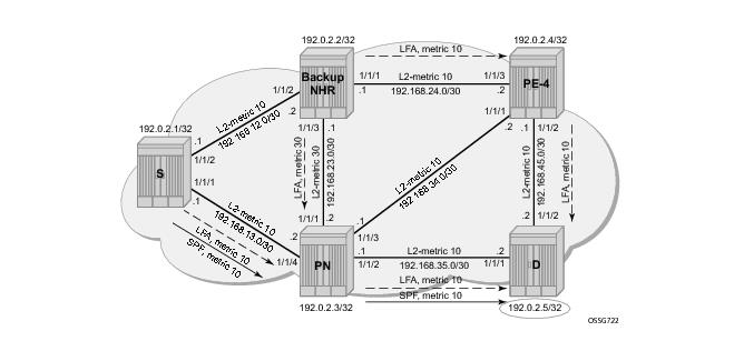
Both inequality formulas are visualized in Figure 159 and
Figure 160 for prefix 192.0.2.5/32 (= PE-5) on PE-1 acting as the source node for LFA next-hop computation.
Prefix 192.0.2.5/32 : SP(PE-2,PE-5) < SP(PE-2,PE-3) + SP(PE-3,PE-5)
10 + 10 < 30 + 10 => OK
Prefix 192.0.2.5/32 : SP(PE-2,PE-5) < SP(PE-2,PE-1) + SP(PE-1,PE-5)
10 + 10 < 10 + (10 + 10) => OK
Prefix 192.0.2.2/32 : SP(PE-3,PE-2) < SP(PE-3,PE-1) + SP(PE-1,PE-2)
30 < 10 + 10 => NOK
Prefix 192.0.2.3/32 : SP(PE-2,PE-3) < SP(PE-2,PE-1) + SP(PE-1,PE-3)
30 < 10 + 10 => NOK
Prefix 192.0.2.4/32 : SP(PE-3,PE-4) < SP(PE-3,PE-1) + SP(PE-1,PE-2)
10 < 10 + 10 => OK
Prefix 192.168.23.0/30 : SP(PE-3,D) < SP(PE-3,PE-1) + SP(PE-1,D)
30 < 10 + 10 => NOK
Prefix 192.168.24.0/30 : SP(PE-3,D) < SP(PE-3,PE-1) + SP(PE-1,D)
30 + 10 < 10 + (10 + 10) => NOK
Prefix 192.168.34.0/30 : SP(PE-2,D) < SP(PE-2,PE-1) + SP(PE-1,D)
30 + 10 < 10 + (10 + 10) => NOK
Prefix 192.168.35.0/30 : SP(PE-2,D) < SP(PE-2,PE-1) + SP(PE-1,D)
30 + 10 < 10 + (10 + 10) => NOK
Prefix 192.168.45.0/30 : SP(PE-3,D) < SP(PE-3,PE-1) + SP(PE-1,D)
10 + 10 < 10 + (10 + 10 + 10) => OK
*A:PE-1# show router isis lfa-coverage
===============================================================================
LFA Coverage
===============================================================================
Topology Level Node IPv4 IPv6
-------------------------------------------------------------------------------
IPV4 Unicast L1 0/0(0%) 3/9(33%) 0/0(0%)
IPV6 Unicast L1 0/0(0%) 0/0(0%) 0/0(0%)
IPV4 Multicast L1 0/0(0%) 0/0(0%) 0/0(0%)
IPV6 Multicast L1 0/0(0%) 0/0(0%) 0/0(0%)
IPV4 Unicast L2 2/4(50%) 3/9(33%) 0/0(0%)
IPV6 Unicast L2 0/0(0%) 0/0(0%) 0/0(0%)
IPV4 Multicast L2 0/0(0%) 0/0(0%) 0/0(0%)
IPV6 Multicast L2 0/0(0%) 0/0(0%) 0/0(0%)
===============================================================================
*A:PE-1#
As stated in RFC 3137, OSPF Stub Router Advertisement, sometimes it is desirable not to have a router used as a transit node. For those cases, it is also desirable not to have that router used as transit node during the LFA next-hop computation. Within IS-IS protocol this is achieved by setting the overload bit. When other routers detect that this bit is set, they will only use this router for packets destined to the overloaded router's directly connected networks and IP prefixes.
*A:PE-2# configure router isis overload timeout 60
## possible value 60 ..1800
## or
## infinity without a timeout value
*A:PE-1# show router isis lfa-coverage
===============================================================================
LFA Coverage
===============================================================================
Topology Level Node IPv4 IPv6
-------------------------------------------------------------------------------
IPV4 Unicast L1 0/0(0%) 3/9(33%) 0/0(0%)
IPV6 Unicast L1 0/0(0%) 0/0(0%) 0/0(0%)
IPV4 Multicast L1 0/0(0%) 0/0(0%) 0/0(0%)
IPV6 Multicast L1 0/0(0%) 0/0(0%) 0/0(0%)
IPV4 Unicast L2 1/4(25%) 3/9(33%) 0/0(0%)
IPV6 Unicast L2 0/0(0%) 0/0(0%) 0/0(0%)
IPV4 Multicast L2 0/0(0%) 0/0(0%) 0/0(0%)
IPV6 Multicast L2 0/0(0%) 0/0(0%) 0/0(0%)
===============================================================================
*A:PE-1#
*A:PE-1# show router route-table alternative
===============================================================================
Route Table (Router: Base)
===============================================================================
Dest Prefix[Flags] Type Proto Age Pref
Next Hop[Interface Name] Metric
Alt-NextHop Alt-
Metric
-------------------------------------------------------------------------------
192.0.2.1/32 Local Local 07d23h49m 0
system 0
192.0.2.2/32 Remote ISIS 07d23h48m 18
192.168.12.2 10
192.168.13.2 (LFA) 20
192.0.2.3/32 Remote ISIS 00h01m59s 18
192.168.13.2 10
192.0.2.4/32 Remote ISIS 00h00m40s 18
192.168.13.2 20
192.0.2.5/32 Remote ISIS 00h01m59s 18
192.168.13.2 20
192.168.12.0/30 Local Local 07d23h48m 0
int-PE-1-PE-2 0
192.168.13.0/30 Local Local 07d23h48m 0
int-PE-1-PE-3 0
192.168.23.0/30 Remote ISIS 00h01m11s 18
192.168.12.2 20
192.168.13.2 (LFA) 30
192.168.24.0/30 Remote ISIS 07d23h48m 18
192.168.12.2 20
192.168.13.2 (LFA) 30
192.168.34.0/30 Remote ISIS 00h01m59s 18
192.168.13.2 20
192.168.35.0/30 Remote ISIS 00h01m59s 18
192.168.13.2 20
192.168.45.0/30 Remote ISIS 00h00m40s 18
192.168.13.2 25
-------------------------------------------------------------------------------
No. of Routes: 12
Flags: n = Number of times nexthop is repeated
Backup = BGP backup route
LFA = Loop-Free Alternate nexthop
S = Sticky ECMP requested
===============================================================================
*A:PE-1#
*A:PE-1# show router isis routes alternative
===============================================================================
Route Table
===============================================================================
Prefix[Flags] Metric Lvl/Typ Ver. SysID/Hostname
NextHop MT AdminTag
Alt-Nexthop Alt- Alt-Type
Metric
-------------------------------------------------------------------------------
192.0.2.1/32 0 2/Int. 3 PE-1
0.0.0.0 0 0
192.0.2.2/32 10 2/Int. 5 PE-2
192.168.12.2 0 0
192.168.13.2(L) 20 LP
192.0.2.3/32 10 2/Int. 43 PE-3
192.168.13.2 0 0
192.0.2.4/32 20 2/Int. 47 PE-3
192.168.13.2 0 0
192.0.2.5/32 20 2/Int. 43 PE-3
192.168.13.2 0 0
192.168.12.0/30 10 2/Int. 4 PE-1
0.0.0.0 0 0
192.168.13.0/30 10 2/Int. 43 PE-1
0.0.0.0 0 0
192.168.23.0/30 20 2/Int. 45 PE-2
192.168.12.2 0 0
192.168.13.2(L) 30 LP
192.168.24.0/30 20 2/Int. 5 PE-2
192.168.12.2 0 0
192.168.13.2(L) 30 LP
192.168.34.0/30 20 2/Int. 43 PE-3
192.168.13.2 0 0
192.168.35.0/30 20 2/Int. 43 PE-3
192.168.13.2 0 0
192.168.45.0/30 25 2/Int. 47 PE-3
192.168.13.2 0 0
-------------------------------------------------------------------------------
No. of Routes: 12
Flags: L = Loop-Free Alternate nexthop
Legend: LP = linkProtection, NP = nodeProtection
===============================================================================
*A:PE-1#
[SP(backup NHR,D) < {SP(backup NHR,S) + SP(S,D)}]
SP(PE-3,D) < SP(PE-3,PE-1) + SP(PE-1,D)
10 + 10 < 10 + (10 + 10) => OK