When multiple LFAs exist, RFC 5286, Basic Specification for IP Fast Reroute: Loop-Free Alternates, chooses the selection of the LFA providing the best coverage of the failure cases. In general, this means that node LFA has preference above link LFA. In some deployments, however, this can lead to suboptimal LFA. For example an aggregation router (typically using lower bandwidth links) protecting a core node/link (typically using high bandwidth links) is potentially undesirable.
For compatibility reasons with the existing MPLS, admin-groups and SRLG, a single set of admin-groups and SRLGs are defined within the configure router if-attribute context from 12.0.R1 onward. Configuration of admin-groups and SRLGs in the
configure router mpls context is deprecated from this release onwards.
*A:PE-7# show router tunnel-table
===============================================================================
Tunnel Table (Router: Base)
===============================================================================
Destination Owner Encap TunnelId Pref Nexthop Metric
-------------------------------------------------------------------------------
192.0.2.5/32 ldp MPLS - 9 192.168.57.1 1000
192.0.2.6/32 ldp MPLS - 9 192.168.67.1 1000
192.0.2.8/32 ldp MPLS - 9 192.168.57.1 2000
192.0.2.9/32 ldp MPLS - 9 192.168.79.2 1000
192.0.2.10/32 ldp MPLS - 9 192.168.107.2 1000
-------------------------------------------------------------------------------
Flags: B = BGP backup route available
E = inactive best-external BGP route
===============================================================================
*A:PE-7#
*A:PE-7# configure router ospf loopfree-alternate
*A:PE-7# show router ospf status | match LFA
LFA : Enabled
*A:PE-7# configure router ldp fast-reroute
*A:PE-7# show router ldp status | match FRR
FRR : Enabled Mcast Upstream FRR : Disabled
*A:PE-7# show router route-table alternative
===============================================================================
Route Table (Router: Base)
===============================================================================
Dest Prefix[Flags] Type Proto Age Pref
Next Hop[Interface Name] Metric
Alt-NextHop Alt-
Metric
-------------------------------------------------------------------------------
192.0.2.5/32 Remote OSPF 16h27m07s 10
192.168.57.1 1000
192.168.67.1 (LFA) 2000
192.0.2.6/32 Remote OSPF 16h27m07s 10
192.168.67.1 1000
192.168.57.1 (LFA) 2000
192.0.2.7/32 Local Local 16h37m53s 0
system 0
192.0.2.8/32 Remote OSPF 16h24m34s 10
192.168.57.1 2000
192.168.67.1 (LFA) 2000
192.0.2.9/32 Remote OSPF 16h22m15s 10
192.168.79.2 1000
192.168.107.2 (LFA) 2000
192.0.2.10/32 Remote OSPF 16h20m19s 10
192.168.107.2 1000
192.168.79.2 (LFA) 2000
192.168.56.0/30 Remote OSPF 16h27m07s 10
192.168.57.1 2000
192.168.67.1 (LFA) 3000
192.168.57.0/30 Local Local 16h29m11s 0
int-PE-7-PE-5 0
192.168.58.0/30 Remote OSPF 16h27m07s 10
192.168.57.1 2000
192.168.67.1 (LFA) 3000
192.168.67.0/30 Local Local 16h28m55s 0
int-PE-7-PE-6 0
192.168.68.0/30 Remote OSPF 16h27m07s 10
192.168.67.1 2000
192.168.57.1 (LFA) 3000
192.168.78.0/30 Remote OSPF 16h24m27s 10
192.168.57.1 3000
192.168.67.1 (LFA) 3000
192.168.79.0/30 Local Local 16h28m16s 0
int-PE-7-PE-9 0
192.168.89.0/30 Remote OSPF 16h22m10s 10
192.168.79.2 2000
192.168.107.2 (LFA) 3000
192.168.107.0/30 Local Local 16h27m52s 0
int-PE-7-PE-10 0
192.168.109.0/30 Remote OSPF 16h22m10s 10
192.168.79.2 2000
192.168.107.2 (LFA) 3000
-------------------------------------------------------------------------------
*A:PE-7#
*A:PE-7# show router ldp bindings active
===============================================================================
Legend: (S) - Static (M) - Multi-homed Secondary Support
(B) - BGP Next Hop (BU) - Alternate Next-hop for Fast Re-Route
===============================================================================
LDP Prefix Bindings (Active)
===============================================================================
Prefix Op IngLbl EgrLbl EgrIntf/LspId EgrNextHop
-------------------------------------------------------------------------------
192.0.2.5/32 Push -- 262143 1/1/4 192.168.57.1
192.0.2.5/32 Push -- 262142BU 1/1/3 192.168.67.1
192.0.2.5/32 Swap 262142 262143 1/1/4 192.168.57.1
192.0.2.5/32 Swap 262142 262142BU 1/1/3 192.168.67.1
192.0.2.6/32 Push -- 262143 1/1/3 192.168.67.1
192.0.2.6/32 Push -- 262142BU 1/1/4 192.168.57.1
192.0.2.6/32 Swap 262141 262143 1/1/3 192.168.67.1
192.0.2.6/32 Swap 262141 262142BU 1/1/4 192.168.57.1
192.0.2.7/32 Pop 262143 -- -- --
192.0.2.8/32 Push -- 262140 1/1/4 192.168.57.1
192.0.2.8/32 Push -- 262140BU 1/1/3 192.168.67.1
192.0.2.8/32 Swap 262140 262140 1/1/4 192.168.57.1
192.0.2.8/32 Swap 262140 262140BU 1/1/3 192.168.67.1
192.0.2.9/32 Push -- 262143 1/1/1 192.168.79.2
192.0.2.9/32 Push -- 262138BU 1/1/2 192.168.107.2
192.0.2.9/32 Swap 262139 262143 1/1/1 192.168.79.2
192.0.2.9/32 Swap 262139 262138BU 1/1/2 192.168.107.2
192.0.2.10/32 Push -- 262143 1/1/2 192.168.107.2
192.0.2.10/32 Push -- 262138BU 1/1/1 192.168.79.2
192.0.2.10/32 Swap 262138 262143 1/1/2 192.168.107.2
192.0.2.10/32 Swap 262138 262138BU 1/1/1 192.168.79.2
-------------------------------------------------------------------------------
*A:PE-7#
*A:PE-x# configure router interface <itf-name> ldp-sync-timer 10
When this timer is set, when a failed interface is subsequently restored, the IGP advertises this link into the network with an infinite metric for the period of this timer. When the failed link is restored, the ldp-sync-timer is started, and LDP adjacencies are brought up over the restored link and a label exchange is completed between the peers. After the
ldp-sync-timer expires, the normal metric is advertised into the network again.
*A:PE-x# configure router route-next-hop-policy template <template name>
Commands within a route-next-hop policy template follow the
begin-abort-commit model. After a
commit, the IGP re-evaluates the template and schedules a new LFA SPF to re-compute the LFA NH for the prefixes associated with this template.
*A:PE-x# configure router if-attribute admin-group <group-name> value <group-value>
*A:PE-x# configure router interface <itf-name> if-attribute admin-group <group-name> [ <group-name> ... (upto 5 max)]
*A:PE-x# configure service vprn <svc-id> interface <itf-name> if-attribute admin-group <group-name> [ <group-name> ... (upto 5 max)]
*A:PE-x# configure service ies <svc-id> interface <itf-name> if-attribute admin-group <group-name> [ <group-name> ... (upto 5 max)]
Third, add the IP admin-group constraints into the route-next-hop policy template one by one. The include-group statement instructs the LFA SPF selection algorithm to select a subset of LFA NHs among the links which belong to one or more of the specified admin groups. A link which does not belong to at least one of the admin-groups is excluded. The
pref option is used to provide a relative preference for the admin group selection. A lower preference value means that LFA SPF will first attempt to select an LFA backup NH which is a member of the corresponding admin group. If none is found, then the admin group with the next higher preference value is evaluated. If no preference is configured, then it is the least preferred (default preference value is 255).
When evaluating multiple include-group statements within the same preference, any link which belongs to one or more of the included admin groups can be selected as an LFA next-hop. There is no relative preference based on how many of those included admin groups the link is a member.
The exclude-group command simply prunes all links belonging to the specified admin group before making the LFA backup NH selection for a prefix. If the same group name is part of both
include and
exclude statements, the exclude statement will takes precedence. In other words, the
exclude statement can be viewed as having an implicit preference value of 0.
*A:PE-x# configure router route-next-hop-policy template <template-name> exclude-group <group-name>
*A:PE-x# configure router route-next-hop-policy template <template-name> include-group <group-name> [pref <preference>]
*A:PE-x# configure router if-attribute srlg-group <group-name> value <group-value>
*A:PE-x# configure router interface <itf-name> if-attribute srlg-group <group-name> [ <group-name> ... (upto 5 max)]
*A:PE-x# configure service vprn <svc-id> interface <itf-name> if-attribute srlg-group <group-name> [ <group-name> ... (upto 5 max)]
*A:PE-x# configure service ies <svc-id> interface <itf-name> if-attribute srlg-group <group-name> [ <group-name> ... (upto 5 max)]
*A:PE-x# configure router route-next-hop-policy template <template-name> srlg-enable
*A:PE-x# configure router route-next-hop-policy template <template-name> protection-type {link|node}
*A:PE-x# configure router route-next-hop-policy template <template-name> nh-type {ip|tunnel}
*A:PE-x# configure router ospf area interface lfa-policy-map route-nh-template <template-name>
*A:PE-x# configure router ospf3 area interface lfa-policy-map route-nh-template <template-name>
*A:PE-x# configure service vprn ospf area interface lfa-policy-map route-nh-template <template-name>
*A:PE-x# configure service vprn ospf3 area interface lfa-policy-map route-nh-template <template-name>
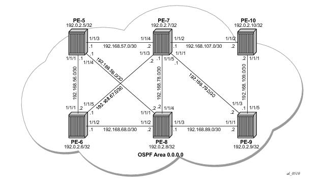
See Figure 279 for the network topology.
*A:PE-7# show router ldp bindings active
===============================================================================
Legend: (S) - Static (M) - Multi-homed Secondary Support
(B) - BGP Next Hop (BU) - Alternate Next-hop for Fast Re-Route
===============================================================================
LDP Prefix Bindings (Active)
===============================================================================
Prefix Op IngLbl EgrLbl EgrIntf/LspId EgrNextHop
-------------------------------------------------------------------------------
192.0.2.5/32 Push -- 262143 1/1/4 192.168.57.1
192.0.2.5/32 Push -- 262142BU 1/1/3 192.168.67.1
192.0.2.5/32 Swap 262136 262143 1/1/4 192.168.57.1
192.0.2.5/32 Swap 262136 262142BU 1/1/3 192.168.67.1
192.0.2.6/32 Push -- 262143 1/1/3 192.168.67.1
192.0.2.6/32 Push -- 262142BU 1/1/4 192.168.57.1
192.0.2.6/32 Swap 262135 262143 1/1/3 192.168.67.1
192.0.2.6/32 Swap 262135 262142BU 1/1/4 192.168.57.1
*A:PE-7# configure router if-attribute admin-group "red" value 1
*A:PE-7# configure router interface "int-PE-7-PE-5" if-attribute admin-group "red"
*A:PE-7# configure router interface "int-PE-7-PE-6" if-attribute admin-group "red"
*A:PE-7# configure router route-next-hop-policy
*A:PE-7>config>router>route-nh# info
begin
template "example1"
exclude-group "red"
exit
commit
*A:PE-7# configure router ospf area 0 interface "int-PE-7-PE-5" lfa-policy-map route-nh-template "example1"
*A:PE-7# configure router ospf area 0 interface "int-PE-7-PE-6" lfa-policy-map route-nh-template "example1"
*A:PE-7# show router ldp bindings active
===============================================================================
Legend: (S) - Static (M) - Multi-homed Secondary Support
(B) - BGP Next Hop (BU) - Alternate Next-hop for Fast Re-Route
===============================================================================
LDP Prefix Bindings (Active)
===============================================================================
Prefix Op IngLbl EgrLbl EgrIntf/LspId EgrNextHop
-------------------------------------------------------------------------------
192.0.2.5/32 Push -- 262143 1/1/4 192.168.57.1
192.0.2.5/32 Push -- 262142BU 1/1/5 192.168.78.2
192.0.2.5/32 Swap 262136 262143 1/1/4 192.168.57.1
192.0.2.5/32 Swap 262136 262142BU 1/1/5 192.168.78.2
192.0.2.6/32 Push -- 262143 1/1/3 192.168.67.1
192.0.2.6/32 Push -- 262141BU 1/1/5 192.168.78.2
192.0.2.6/32 Swap 262135 262143 1/1/3 192.168.67.1
192.0.2.6/32 Swap 262135 262141BU 1/1/5 192.168.78.2
*A:PE-7# configure router if-attribute srlg-group "blue" value 2
*A:PE-7# configure router interface "int-PE-7-PE-5" if-attribute srlg-group "blue"
*A:PE-7# configure router interface "int-PE-7-PE-6" if-attribute srlg-group "blue"
*A:PE-7# configure router route-next-hop-policy
*A:PE-7>config>router>route-nh# info
begin
template "example2"
srlg-enable
exit
commit
*A:PE-7# configure router ospf area 0 interface "int-PE-7-PE-5" lfa-policy-map route-nh-template "example2"
*A:PE-7# configure router ospf area 0 interface "int-PE-7-PE-6" lfa-policy-map route-nh-template "example2"
*A:PE-7# show router ldp bindings active
===============================================================================
Legend: (S) - Static (M) - Multi-homed Secondary Support
(B) - BGP Next Hop (BU) - Alternate Next-hop for Fast Re-Route
===============================================================================
LDP Prefix Bindings (Active)
===============================================================================
Prefix Op IngLbl EgrLbl EgrIntf/LspId EgrNextHop
-------------------------------------------------------------------------------
192.0.2.5/32 Push -- 262143 1/1/4 192.168.57.1
192.0.2.5/32 Push -- 262142BU 1/1/5 192.168.78.2
192.0.2.5/32 Swap 262136 262143 1/1/4 192.168.57.1
192.0.2.5/32 Swap 262136 262142BU 1/1/5 192.168.78.2
192.0.2.6/32 Push -- 262143 1/1/3 192.168.67.1
192.0.2.6/32 Push -- 262141BU 1/1/5 192.168.78.2
192.0.2.6/32 Swap 262135 262143 1/1/3 192.168.67.1
192.0.2.6/32 Swap 262135 262141BU 1/1/5 192.168.78.2
Enable IP FRR and setup an RSVP LSP tunnel
1 towards 192.0.2.6 with a strict MPLS path going over PE-7 to PE-9 to PE-8 toPE-6.
*A:PE-7# configure router ip-fast-reroute
*A:PE-7# configure router mpls
interface "system"
no shutdown
exit
interface "int-PE-7-PE-9"
no shutdown
exit
path "P-PE-7-PE-9-PE-8-PE6"
hop 10 192.168.79.2 strict
hop 20 192.168.89.1 strict
hop 30 192.168.68.1 strict
no shutdown
exit
lsp "LSP-PE-7-PE-6"
to 192.0.2.6
primary "P-PE-7-PE-9-PE-8-PE6"
exit
no shutdown
exit
no shutdown
*A:PE-7# configure router ospf rsvp-shortcut
*A:PE-7# configure router mpls lsp "LSP-PE-7-PE-6" igp-shortcut lfa-only
*A:PE-7# show router tunnel-table 192.0.2.6
===============================================================================
Tunnel Table (Router: Base)
===============================================================================
Destination Owner Encap TunnelId Pref Nexthop Metric
-------------------------------------------------------------------------------
192.0.2.6/32 rsvp MPLS 1 7 192.168.79.2 16777215
192.0.2.6/32 ldp MPLS - 9 192.168.67.1 1000
*A:PE-7# show router mpls lsp
===============================================================================
MPLS LSPs (Originating)
===============================================================================
LSP Name To Tun Fastfail Adm Opr
Id Config
-------------------------------------------------------------------------------
LSP-PE-7-PE-6 192.0.2.6 1 No Up Up
-------------------------------------------------------------------------------
LSPs : 1
===============================================================================
*A:PE-7#
*A:PE-7# show router route-table alternative 192.0.2.6/32
===============================================================================
Route Table (Router: Base)
===============================================================================
Dest Prefix[Flags] Type Proto Age Pref
Next Hop[Interface Name] Metric
Alt-NextHop Alt-
Metric
-------------------------------------------------------------------------------
192.0.2.6/32 Remote OSPF 00h02m44s 10
192.168.67.1 1000
192.168.57.1 (LFA) 2000
-------------------------------------------------------------------------------
*A:PE-7#
Define a route-next-hop policy template example3, where nh-type is set to
tunnel.
*A:PE-7# configure router route-next-hop-policy
*A:PE-7>config>router>route-nh# info
begin
template "example3"
nh-type tunnel
exit
commit
From the moment that route-next-hop policy template example3 is applied to the OSPF interface towards PE-6, the LFA NH uses the RSVP tunnel. Note that the reference to the RSVP tunnel-ID (1) in the following show output corresponds with the tunnel-ID shown in the previous
show router tunnel-table 192.0.2.6 output:
*A:PE-7# configure router ospf area 0 interface "int-PE-7-PE-6" lfa-policy-map route-nh-template "example3"
*A:PE-7# show router route-table alternative 192.0.2.6/32
===============================================================================
Route Table (Router: Base)
===============================================================================
Dest Prefix[Flags] Type Proto Age Pref
Next Hop[Interface Name] Metric
Alt-NextHop Alt-
Metric
-------------------------------------------------------------------------------
192.0.2.6/32 Remote OSPF 00h01m49s 10
192.168.67.1 1000
192.0.2.6 (LFA) (tunneled:RSVP:1) 65535
-------------------------------------------------------------------------------
*A:PE-7#
*A:PE-7# show router fib 1 nh-table-usage
===============================================================================
FIB Next-Hop Summary
===============================================================================
IPv4/IPv6 Active Available
-------------------------------------------------------------------------------
IP Next-Hop 10 16383
Tunnel Next-Hop 1 993279
===============================================================================
*A:PE-7#
A:PE-7# configure router policy-options
begin
prefix-list "lo0-PE-5"
prefix 192.0.2.5/32 exact
exit
policy-statement "PE-5-exclude-LFA"
entry 10
from
prefix-list "lo0-PE-5"
exit
action accept
exit
exit
exit
commit
*A:PE-7# configure router ospf loopfree-alternate-exclude prefix-policy "PE-5-exclude-LFA"
*A:PE-7# show router ldp bindings active prefix 192.0.2.5/32
===============================================================================
Legend: (S) - Static (M) - Multi-homed Secondary Support
(B) - BGP Next Hop (BU) - Alternate Next-hop for Fast Re-Route
===============================================================================
LDP Prefix Bindings (Active)
===============================================================================
Prefix Op IngLbl EgrLbl EgrIntf/LspId EgrNextHop
-------------------------------------------------------------------------------
192.0.2.5/32 Push -- 262143 1/1/4 192.168.57.1
192.0.2.5/32 Swap 262136 262143 1/1/4 192.168.57.1
-------------------------------------------------------------------------------
No. of Prefix Active Bindings: 2
===============================================================================