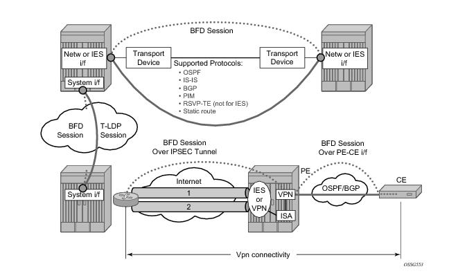
Figure 265 provides an overview of the possible BFD implementations and shows all protocols that can be bound to a BFD session.
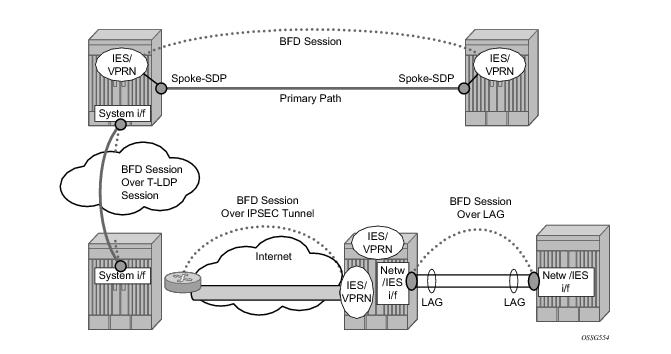
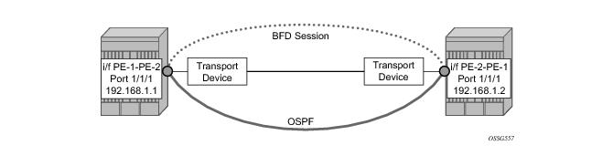
Figure 266 shows the most relevant scenarios where BFD centralized sessions are used.
configure
router
interface PE-1-PE-2
address 192.168.1.1/30
port 1/1/1
bfd 100 receive 100 multiplier 3
exit
exit
exit
configure
router
interface PE-2-PE-1
address 192.168.1.2/30
port 1/1/1
bfd 100 receive 100 multiplier 3
exit
exit
exit
The following show commands are used to verify the BFD configuration on the router interfaces on PE1 and PE2.
A:PE1# show router bfd interface
===============================================================================
BFD Interface
===============================================================================
Interface name Tx Interval Rx Interval Multiplier
-------------------------------------------------------------------------------
PE-1-PE-2 100 100 3
-------------------------------------------------------------------------------
No. of BFD Interfaces: 1
===============================================================================
A:PE1#
A:PE2# show router bfd interface
===============================================================================
BFD Interface
===============================================================================
Interface name Tx Interval Rx Interval Multiplier
-------------------------------------------------------------------------------
PE-2-PE-1 100 100 3
-------------------------------------------------------------------------------
No. of BFD Interfaces: 1
===============================================================================
A:PE2#
bfd <transmit-interval> [receive <receive-interval>] [multiplier <multiplier>] [echo-receive <echo-interval>] [type <cpm-np>]
no bfd
<transmit-interval> : [10..100000] in milliseconds
<receive-interval> : [10..100000] in milliseconds
<multiplier> : [3..20]
<echo-interval> : [100..100000] in milliseconds
<cpm-np> : keyword - use CPM network processor
configure
router
interface PE-2-PE-1
bfd 10 receive 10 multiplier 3 type cpm-np
exit
exit
exit
The BFD session should come up. To verify it, execute a show router bfd session command (bound to OSPF in the following example).
A:PE1# show router bfd session
===============================================================================
BFD Session
===============================================================================
Interface State Tx Intvl Rx Intvl Multipl
Remote Address Protocol Tx Pkts Rx Pkts Type
-------------------------------------------------------------------------------
PE-1-PE-2 Up (3) 100 100 3
192.168.1.2 ospf 165 174 iom
-------------------------------------------------------------------------------
No. of BFD sessions: 1
===============================================================================
A:PE1#
A:PE-1# show router ospf neighbor
===============================================================================
OSPF Neighbors
===============================================================================
Interface-Name Rtr Id State Pri RetxQ TTL
-------------------------------------------------------------------------------
PE-1-PE-2 192.0.2.1 Full 1 0 34
-------------------------------------------------------------------------------
...
===============================================================================
A:PE-1#
A:PE-2# show log log-id 99
===============================================================================
Event Log 99
===============================================================================
Description : Default System Log
Memory Log contents [size=500 next event=7845 (wrapped)]
7844 2010/10/02 16:43:30.21 UTC MINOR: VRTR #2020 Base 192.168.1.1
BFD Session on node 192.168.1.1 has been deleted.
7843 2010/10/02 16:43:30.21 UTC MAJOR: VRTR #2013 Base Max supported sessions reached
The number of BFD sessions on slot 1 has exceeded 250, constrained by maxSessionsPerSlot”
A:PE2# show router bfd session summary
=============================
BFD Session Summary
=============================
Termination Session Count
-----------------------------
central 0
cpm-np 1
iom, slot 1 250
iom, slot 2 0
iom, slot 3 0
iom, slot 4 0
iom, slot 5 0
Total 251
=============================
If the show router bfd session command reports that the BFD session is down, the check the BFD peer's configuration and state.
The following log 99 output reports PE-1 logs after a misconfiguration of PE-2 (disabling BFD on the OSPF interface).
A:PE-1# show log log-id 99
===============================================================================
Event Log 99
===============================================================================
Description : Default System Log
Memory Log contents [size=500 next event=7 (not wrapped)]
6 2010/10/02 08:47:35.91 UTC WARNING: OSPF #2002 Base VR: 1 OSPFv2 (0)
LCL_RTR_ID 192.0.2.1: Neighbor 192.0.2.2 on PE-1-PE-2 router state changed to full (event EXC_DONE)
5 2010/10/02 08:47:35.91 UTC MINOR: VRTR #2021 Base 192.168.1.2
BFD: The protocols using BFD session on node 192.168.1.2 have changed.
4 2010/10/02 08:47:33.10 UTC WARNING: OSPF #2002 Base VR: 1 OSPFv2 (0)
LCL_RTR_ID 192.0.2.1: Neighbor 192.0.2.2 on PE-1-PE-2 router state changed to down (event BFD_DOWN)
3 2010/10/02 08:47:33.10 UTC MINOR: VRTR #2021 Base 192.168.1.2
BFD: The protocols using BFD session on node 192.168.1.2 have changed.
2 2010/10/02 08:47:33.10 UTC MAJOR: VRTR #2012 Base 192.168.1.2
BFD: Local Discriminator 4009 BFD session to node 192.168.1.2 is down due to noHeartBeat
A:PE-1# show router bfd session
===============================================================================
BFD Session
===============================================================================
Interface State Tx Intvl Rx Intvl Multipl
Remote Address Protocols Tx Pkts Rx Pkts Type
-------------------------------------------------------------------------------
PE-1-PE-2 Down (1) 100 100 3
192.168.1.2 ospf2 10 0 iom
The show router bfd session src <ip-address> detail command can help in debugging the BFD session.
A:PE-1# show router bfd session src 192.168.1.1 detail
===============================================================================
BFD Session
===============================================================================
Remote Address : 192.168.1.2
Admin State : Up Oper State : Up (3)
Protocols : ospf2 pim isis static
Rx Interval : 100 Tx Interval : 100
Multiplier : 3 Echo Interval : 0
Recd Msgs : 24046 Sent Msgs : 25723
Up Time : 0d 00:40:05 Up Transitions : 1
Down Time : None Down Transitions : 0
Version Mismatch : 0
Forwarding Information
Local Discr : 4002 Local State : Up (3)
Local Diag : 0 (None) Local Mode : Async
Local Min Tx : 100 Local Mult : 3
Last Sent : 10/08/2010 20:30:27 Local Min Rx : 100
Type : iom
Remote Discr : 4001 Remote State : Up (3)
Remote Diag : 0 (None) Remote Mode : Async
Remote Min Tx : 100 Remote Mult : 3
Last Recv : 10/08/2010 20:30:27 Remote Min Rx : 100
===============================================================================
configure
router
isis
interface PE-1-PE-2
bfd-enable ipv4
exit
exit
exit
exit
configure
router
isis
interface PE-2-PE-1
bfd-enable ipv4
exit
exit
exit
exit
A:PE1# show router bfd session
===============================================================================
BFD Session
===============================================================================
Interface State Tx Intvl Rx Intvl Multipl
Remote Address Protocol Tx Pkts Rx Pkts Type
-------------------------------------------------------------------------------
PE-1-PE-2 Up (3) 100 100 3
192.168.1.2 isis 165 174 iom
-------------------------------------------------------------------------------
No. of BFD sessions: 1
===============================================================================
A:PE1#
A:PE2# show router bfd session
===============================================================================
BFD Session
===============================================================================
Interface State Tx Intvl Rx Intvl Multipl
Remote Address Protocol Tx Pkts Rx Pkts Type
-------------------------------------------------------------------------------
PE-2-PE-1 Up (3) 100 100 3
192.168.1.1 isis 496 487 iom
-------------------------------------------------------------------------------
No. of BFD sessions: 1
===============================================================================
A:PE2#
configure
router
ospf
interface PE-1-PE-2
bfd-enable
exit
exit
exit
exit
configure
router
ospf
interface PE-2-PE-1
bfd-enable
exit
exit
exit
exit
A:PE1# show router bfd session
===============================================================================
BFD Session
===============================================================================
Interface State Tx Intvl Rx Intvl Multipl
Remote Address Protocol Tx Pkts Rx Pkts Type
-------------------------------------------------------------------------------
PE-1-PE-2 Up (3) 100 100 3
192.168.1.2 ospf 170 179 iom
-------------------------------------------------------------------------------
No. of BFD sessions: 1
===============================================================================
A:PE1#
A:PE2# show router bfd session
===============================================================================
BFD Session
===============================================================================
Interface State Tx Intvl Rx Intvl Multipl
Remote Address Protocol Tx Pkts Rx Pkts Type
-------------------------------------------------------------------------------
PE-2-PE-1 Up (3) 100 100 3
192.168.1.1 ospf 501 492 iom
-------------------------------------------------------------------------------
No. of BFD sessions: 1
===============================================================================
A:PE2#
configure
router
pim
interface PE-1-PE-2
bfd-enable
exit
exit
exit
exit
configure
router
pim
interface PE-2-PE-1
bfd-enable
exit
exit
exit
exit
A:PE1# show router bfd session
===============================================================================
BFD Session
===============================================================================
Interface State Tx Intvl Rx Intvl Multipl
Remote Address Protocol Tx Pkts Rx Pkts Type
-------------------------------------------------------------------------------
PE-1-PE-2 Up (3) 100 100 3
192.168.1.2 ospf2 pim 3874 3845 iom
-------------------------------------------------------------------------------
No. of BFD sessions: 1
===============================================================================
A:PE1#
A:PE2# show router bfd session
===============================================================================
BFD Session
===============================================================================
Interface State Tx Intvl Rx Intvl Multipl
Remote Address Protocol Tx Pkts Rx Pkts Type
-------------------------------------------------------------------------------
PE-1-PE-2 Up (3) 100 100 3
192.168.1.1 ospf2 pim 3137 3145 iom
-------------------------------------------------------------------------------
No. of BFD sessions: 1
===============================================================================
A:PE2#
configure
router
static-route 10.1.2.0/24 next-hop 192.168.1.2
exit
exit
configure
router
static-route 10.1.1.0/24 next-hop 192.168.1.1
exit
exit
A:PE1# show router route-table
===============================================================================
Route Table (Router: Base)
===============================================================================
Dest Prefix Type Proto Age Pref
Next Hop[Interface Name] Metric
-------------------------------------------------------------------------------
10.1.2.0/24 Remote Static 00h20m55s 5
192.168.1.2 1
A:PE2# show router route-table
===============================================================================
Route Table (Router: Base)
===============================================================================
Dest Prefix Type Proto Age Pref
Next Hop[Interface Name] Metric
-------------------------------------------------------------------------------
10.1.1.0/24 Remote Static 00h21m15s 5
192.168.1.1 1
configure
router
static-route 10.1.2.0/24 next-hop 192.168.1.2 bfd-enable
exit
exit
configure
router
static-route 10.1.1.0/24 next-hop 192.168.1.1 bfd-enable
exit
exit
A:PE1# show router bfd session
===============================================================================
BFD Session
===============================================================================
Interface State Tx Intvl Rx Intvl Multipl
Remote Address Protocol Tx Pkts Rx Pkts Type
-------------------------------------------------------------------------------
PE-1-PE-2 Up (3) 100 100 3
192.168.1.2 static 699 661 iom
-------------------------------------------------------------------------------
No. of BFD sessions: 1
===============================================================================
A:PE2# show router bfd session
===============================================================================
BFD Session
===============================================================================
Interface State Tx Intvl Rx Intvl Multipl
Remote Address Protocol Tx Pkts Rx Pkts Type
-------------------------------------------------------------------------------
PE-2-PE-1 Up (3) 100 100 3
192.168.1.1 static 691 729 iom
-------------------------------------------------------------------------------
No. of BFD sessions: 1
===============================================================================
configure
service
ies 2 customer 1 create
interface IES_PE-1-PE-2 create
address 192.168.3.1/30
spoke-sdp 1020:1 create
exit
exit
no shutdown
exit
exit
exit
configure
service
ies 2 customer 1 create
interface IES_PE-2-PE-1 create
address 192.168.3.2/30
spoke-sdp 2010:1 create
exit
exit
no shutdown
exit
exit
exit
On PE-1:
configure
router
ospf
traffic-engineering
area 0.0.0.0
interface IES-PE-1-PE-2
exit
exit
exit
exit
exit
configure
router
ospf
traffic-engineering
area 0.0.0.0
interface IES-PE-2-PE-1
exit
exit
exit
exit
exit
A:PE-1# show service id 1 base
===============================================================================
Service Basic Information
===============================================================================
Service Id : 2 Vpn Id : 0
Service Type : IES
Customer Id : 1
Last Status Change: 09/30/2010 08:09:22
Last Mgmt Change : 09/30/2010 08:08:31
Admin State : Up Oper State : Up
SAP Count : 0
...
===============================================================================
A:PE-1#
A:PE-1# show router ospf neighbor
===============================================================================
OSPF Neighbors
===============================================================================
Interface-Name Rtr Id State Pri RetxQ TTL
-------------------------------------------------------------------------------
IES-PE-1-PE-2 192.0.2.2 Full 1 0 34
-------------------------------------------------------------------------------
===============================================================================
A:PE-1#
A:PE-2# show service id 2 base
===============================================================================
Service Basic Information
===============================================================================
Service Id : 2 Vpn Id : 0
Service Type : IES
Customer Id : 1
Last Status Change: 09/30/2010 08:16:50
Last Mgmt Change : 09/30/2010 08:16:50
Admin State : Up Oper State : Up
SAP Count : 0
...
===============================================================================
A:PE-2#
A:PE-2# show router ospf neighbor
===============================================================================
OSPF Neighbors
===============================================================================
Interface-Name Rtr Id State Pri RetxQ TTL
-------------------------------------------------------------------------------
IES-PE-2-PE-1 192.0.2.1 Full 1 0 33
-------------------------------------------------------------------------------
...
===============================================================================
A:PE-2#
configure service ies 2
interface IES-PE-1-PE-2
bfd 100 receive 100 multiplier 3
exit
no shutdown
exit
configure service ies 2
interface IES-PE-2-PE-1
bfd 100 receive 100 multiplier 3
exit
no shutdown
exit
A:PE-1# configure router ospf area 0.0.0.0 interface IES-PE-1-PE-2 bfd-enable
A:PE-2# configure router ospf area 0.0.0.0 interface IES-PE-2-PE-1 bfd-enable
A:PE-1# show router bfd session
===============================================================================
BFD Session
===============================================================================
Interface State Tx Intvl Rx Intvl Multipl
Remote Address Protocols Tx Pkts Rx Pkts Type
-------------------------------------------------------------------------------
IES-PE-1-PE-2 Up (3) 100 100 3
192.168.3.2 ospf2 N/A N/A cpm-np
-------------------------------------------------------------------------------
No. of BFD sessions: 1
A:PE-2# show router bfd session
===============================================================================
BFD Session
===============================================================================
Interface State Tx Intvl Rx Intvl Multipl
Remote Address Protocols Tx Pkts Rx Pkts Type
-------------------------------------------------------------------------------
IES-PE-2-PE-1 Up (3) 100 100 3
192.168.3.1 ospf2 N/A N/A cpm-np
-------------------------------------------------------------------------------
No. of BFD sessions: 1
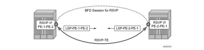
configure router
mpls
interface system
exit
interface PE-1-PE-2
exit
exit
rsvp
interface system
exit
interface PE-1-PE-2
exit
no shutdown
exit
mpls
path dyn
no shutdown
exit
lsp LSP-PE-1-PE-2
to 192.0.1.2
cspf
primary dyn
exit
no shutdown
exit
no shutdown
exit
exit
configure router
mpls
interface system
exit
interface PE-2-PE-1
exit
exit
rsvp
interface system
exit
interface PE-2-PE-1
exit
no shutdown
exit
mpls
path dyn
no shutdown
exit
lsp LSP-PE-2-PE-1
to 192.0.1.1
cspf
primary dyn
exit
no shutdown
exit
no shutdown
exit
exit
A:PE-1# show router rsvp session
===============================================================================
RSVP Sessions
===============================================================================
From To Tunnel LSP Name State
ID ID
-------------------------------------------------------------------------------
192.0.2.2 192.0.2.1 2 516 LSP-PE-2-PE-1::dyn Up
192.0.2.1 192.0.2.2 1 61446 LSP-PE-1-PE-2::dyn Up
-------------------------------------------------------------------------------
Sessions : 2
===============================================================================
A:PE-1#
configure
router
rsvp
interface PE-1-PE-2
bfd-enable
exit
no shutdown
exit
exit
exit
configure
router
rsvp
interface PE-2-PE-1
bfd-enable
exit
no shutdown
exit
exit
exit
===============================================================================
BFD Session
===============================================================================
Interface State Tx Intvl Rx Intvl Multipl
Remote Address Protocols Tx Pkts Rx Pkts Type
-------------------------------------------------------------------------------
PE-1-PE-2 Up (3) 100 100 3
192.168.1.2 rsvp 31515 31506 iom
-------------------------------------------------------------------------------
No. of BFD sessions: 1
===============================================================================
===============================================================================
BFD Session
===============================================================================
Interface State Tx Intvl Rx Intvl Multipl
Remote Address Protocols Tx Pkts Rx Pkts Type
-------------------------------------------------------------------------------
PE-2-PE-1 Up (3) 100 100 3
192.168.1.1 rsvp 31563 31572 iom
-------------------------------------------------------------------------------
No. of BFD sessions: 1
===============================================================================
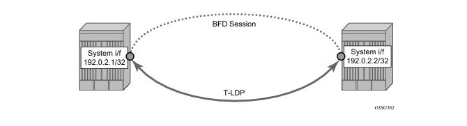
configure
router
interface system
address 192.0.2.1/32
bfd 3000 receive 3000 multiplier 3
exit
exit
exit
On PE-1:
B:PE-1# show router ldp session
==============================================================================
LDP Sessions
==============================================================================
Peer LDP Id Adj Type State Msg Sent Msg Recv Up Time
------------------------------------------------------------------------------
192.0.2.2 Targeted Established 35 41 0d 00:02:50
------------------------------------------------------------------------------
==============================================================================
B:PE-2# show router ldp session
==============================================================================
LDP Sessions
==============================================================================
Peer LDP Id Adj Type State Msg Sent Msg Recv Up Time
------------------------------------------------------------------------------
192.0.2.1 Targeted Established 27 23 0d 00:01:32
------------------------------------------------------------------------------==============================================================================
configure
router
ldp
targeted-session
peer 192.0.2.2
bfd-enable
exit
exit
exit
exit
exit
A:PE-1# show router bfd session
===============================================================================
BFD Session
===============================================================================
Interface State Tx Intvl Rx Intvl Multipl
Remote Address Protocols Tx Pkts Rx Pkts Type
-------------------------------------------------------------------------------
system Up (3) 100 100 3
192.0.2.2 ldp N/A N/A cpm-np
A:PE-1# show router bfd session
===============================================================================
BFD Session
===============================================================================
Interface State Tx Intvl Rx Intvl Multipl
Remote Address Protocols Tx Pkts Rx Pkts Type
-------------------------------------------------------------------------------
system Up (3) 100 100 3
192.0.2.1 ldp N/A N/A cpm-np
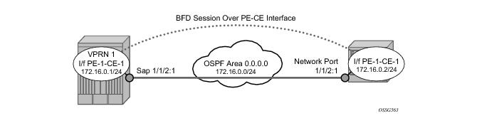
config
service
vprn 1 customer 1 create
route-distinguisher 1:1
vrf-target target:1:1
interface PE-1-CE-1 create
address 172.16.0.1/24
bfd 100 receive 100 multiplier 3
sap 1/1/1:1 create
exit
exit
ospf
area 0.0.0.0
interface PE-1-CE-1
exit
exit
exit
no shutdown
exit
exit
exit
configure
router
interface CE-1-PE-1
address 172.16.0.2/24
port 1/1/1:1
bfd 100 receive 100 multiplier 3
exit
ospf
area 0.0.0.0
interface CE-1-PE-1
exit
exit
exit
exit
exit
A:PE-1>config>service>vprn# show router 1 ospf neighbor
===============================================================================
OSPF Neighbors
===============================================================================
Interface-Name Rtr Id State Pri RetxQ TTL
-------------------------------------------------------------------------------
PE-1-CE-1 192.0.2.5 Full 1 2 33
-------------------------------------------------------------------------------
No. of Neighbors: 1
===============================================================================
A:CE-1# show router ospf neighbor
===============================================================================
OSPF Neighbors
===============================================================================
Interface-Name Rtr Id State Pri RetxQ TTL
-------------------------------------------------------------------------------
CE-1-PE-1 192.0.2.1 Full 1 0 31
-------------------------------------------------------------------------------
No. of Neighbors: 1
===============================================================================
configure service vprn 1 ospf area 0.0.0.0 interface PE-1-CE-1 bfd-enable
configure router ospf area 0.0.0.0 interface CE-1-PE-1 bfd-enable
A:PE-1# show router 1 bfd session
===============================================================================
BFD Session
===============================================================================
Interface State Tx Intvl Rx Intvl Multipl
Remote Address Protocols Tx Pkts Rx Pkts Type
-------------------------------------------------------------------------------
PE-1-CE-1 Up (3) 100 100 3
172.16.0.2 ospf2 6331 6340 iom
-------------------------------------------------------------------------------
No. of BFD sessions: 1
A:CE-1# show router bfd session
===============================================================================
BFD Session
===============================================================================
Interface State Tx Intvl Rx Intvl Multipl
Remote Address Protocols Tx Pkts Rx Pkts Type
-------------------------------------------------------------------------------
CE-1-PE-1 Up (3) 100 100 3
172.16.0.1 ospf2 6691 6682 iom
-------------------------------------------------------------------------------
No. of BFD sessions: 1
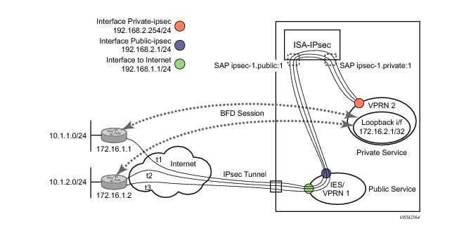
configure
card 1
card-type iom3-xp
mda 1
mda-type isa-tunnel
exit
mda 2
mda-type m10-1gb-sfp-b
exit
exit
exit
configure service
vprn 1 customer 1 create
route-distinguisher 1:1
interface toInternet create
address 192.168.1.1/24
sap 1/2/1 create
exit
exit
interface public-ipsec create
address 192.168.2.1/24
sap tunnel-1.public:1 create
exit
exit
no shutdown
exit
vprn 2 customer 1 create
ipsec
security-policy 1 create
entry 10 create
local-ip 192.168.3.1/32
remote-ip any
exit
exit
exit
route-distinguisher 1:2
interface private-ipsec tunnel create
sap tunnel-1.private:1 create
ipsec-tunnel t1 create
local-gateway-address 192.168.2.254 peer 172.16.1.1 delivery-service 1
exit
exit
ipsec-tunnel t2 create
local-gateway-address 192.168.2.254 peer 172.16.1.2 delivery-service 1
exit
exit
ipsec-tunnel t3 create
local-gateway-address 192.168.2.254 peer 172.16.1.2 delivery-service 1
exit
exit
exit
exit
interface loop create
address 172.16.2.1/32
loopback
exit
static-route 10.1.1.0/24 ipsec-tunnel t1
static-route 10.1.2.0/24 ipsec-tunnel t2 metric 1
static-route 10.1.2.0/24 ipsec-tunnel t3 metric 5
no shutdown
configure service vprn 2
interface loop
bfd 100 receive 100 multiplier 3
exit
exit
And finally enable BFD within the tunnels.
configure service
vprn 2
interface private-ipsec tunnel
sap tunnel-1.private:1
ipsec-tunnel t1
bfd-enable service 2 interface loop dst-ip 172.16.1.1
exit
ipsec-tunnel t2
bfd-enable service 2 interface loop dst-ip 172.16.1.2
bfd-designate
exit
ipsec-tunnel t3
bfd-enable service 2 interface loop dst-ip 172.16.1.2
exit all
|
•
|
service < service-id> — Specifies the service-id where the BFD session resides.
|
|
•
|
interface < interface-name> — Specifies the name of the interface used by the BFD session.
|
|
•
|
dst-ip < ip-address> — Specifies the destination address to be used for the BFD session.
|
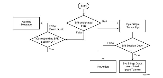
Referring to Figure 276 and to the above configuration, the tunnels t2 and t3 share the same BFD-session. Tunnel t2 is the bfd-designated tunnel, the BFD session runs within it and the other tunnel t3 shares its BFD session. If the BFD session goes down, the system will bring down both the designated tunnel t2 and the associated tunnel t3.
The state machine in Figure 277 shows the decision process in case of shared BFD sessions.
configure service ies 10 customer 1 create
interface vrrp_ies_PE1 create
address 192.168.1.1/24
sap 1/1/3:10 create
exit
exit
no shutdown
exit
configure service ies 10 customer 1 create
interface vrrp_ies_PE2 create
address 192.168.1.2/24
sap 1/1/3:10 create
exit
exit
no shutdown
exit
Verify that the IES services are operational (show service service-using) and verify that you can ping the remote interface IP address.
configure service ies 10 interface vrrp_ies_PE1
vrrp 10 owner
backup 192.168.1.1
exit
vrrp 30
backup 192.168.1.2
ping-reply
telnet-reply
ssh-reply
exit
configure service ies 10 interface vrrp_ies_PE2
vrrp 10
backup 192.168.1.1
ping-reply
telnet-reply
ssh-reply
exit
vrrp 30 owner
backup 192.168.1.2
exit
configure service ies 10 interface vrrp_ies_PE1
vrrp 10 owner
bfd-enable 10 interface vrrp_ies_PE1 dst-ip 192.168.1.2
exit
vrrp 30
bfd-enable 10 interface vrrp_ies_PE1 dst-ip 192.168.1.2
exit
configure service ies 10 interface vrrp_ies_PE2
vrrp 10 owner
bfd-enable 10 interface vrrp_ies_PE2 dst-ip 192.168.1.1
exit
vrrp 30
bfd-enable 10 interface vrrp_ies_PE2 dst-ip 192.168.1.1
exit
configure service ies 10 interface vrrp_ies_PE1
bfd 1000 receive 1000 multiplier 3
configure service ies 10 interface vrrp_ies_PE2
bfd 1000 receive 1000 multiplier 3
A:PE1>show router bfd session src 192.168.1.1 detail
===============================================================================
BFD Session
===============================================================================
Remote Address : 192.168.1.2
Admin State : Up Oper State : Up (3)
Protocols : vrrp
Rx Interval : 100 Tx Interval : 100
Multiplier : 3 Echo Interval : 0
Recd Msgs : 7404 Sent Msgs : 7412
Up Time : 0d 00:04:26 Up Transitions : 2
Down Time : None Down Transitions : 1
Version Mismatch : 0
Forwarding Information
Local Discr : 4006 Local State : Up (3)
Local Diag : 1 (Detect time expired) Local Mode : Async
Local Min Tx : 100 Local Mult : 3
Last Sent : 12/14/2010 17:44:34 Local Min Rx : 100
Type : iom
Remote Discr : 4003 Remote State : Up (3)
Remote Diag : 1 (Detect time expired) Remote Mode : Async
Remote Min Tx : 100 Remote Mult : 3
Last Recv : 12/14/2010 17:44:34 Remote Min Rx : 100
===============================================================================
show router vrrp instance interface vrrp_ies_PE1
===============================================================================
VRRP Instances for interface vrrp_ies_PE1
===============================================================================
-------------------------------------------------------------------------------
VRID 10
-------------------------------------------------------------------------------
Owner : Yes VRRP State : Master
Primary IP of Master: 192.168.1.1 (Self)
Primary IP : 192.168.1.1 Standby-Forwarding: Disabled
VRRP Backup Addr : 192.168.1.1
Admin State : Up Oper State : Up
Up Time : 12/14/2010 16:47:47 Virt MAC Addr : 00:00:5e:00:01:0a
Auth Type : None
Config Mesg Intvl : 1 In-Use Mesg Intvl : 1
Base Priority : 255 In-Use Priority : 255
Init Delay : 0 Init Timer Expires: 0.000 sec
Creation State : Active
-------------------------------------------------------------------------------
BFD Interface
-------------------------------------------------------------------------------
Service ID : 10
Interface Name : vrrp_ies_PE1
Src IP : 192.168.1.1
Dst IP : 192.168.1.2
Session Oper State : connected
-------------------------------------------------------------------------------
Master Information
-------------------------------------------------------------------------------
Primary IP of Master: 192.168.1.1 (Self)
Addr List Mismatch : No Master Priority : 255
Master Since : 12/14/2010 16:47:47
-------------------------------------------------------------------------------
Masters Seen (Last 32)
-------------------------------------------------------------------------------
Primary IP of Master Last Seen Addr List Mismatch Msg Count
-------------------------------------------------------------------------------
192.168.1.1 12/14/2010 16:47:47 No 0
192.168.1.2 12/14/2010 17:39:57 No 5
-------------------------------------------------------------------------------
Statistics
-------------------------------------------------------------------------------
Become Master : 7 Master Changes : 7
Adv Sent : 347577 Adv Received : 5
Pri Zero Pkts Sent : 6 Pri Zero Pkts Rcvd: 0
Preempt Events : 0 Preempted Events : 0
Mesg Intvl Discards : 0 Mesg Intvl Errors : 0
Addr List Discards : 0 Addr List Errors : 0
Auth Type Mismatch : 0 Auth Failures : 0
Invalid Auth Type : 0 Invalid Pkt Type : 0
IP TTL Errors : 0 Pkt Length Errors : 0
Total Discards : 0
-------------------------------------------------------------------------------
VRID 30
-------------------------------------------------------------------------------
Owner : No VRRP State : Backup
Primary IP of Master: 192.168.1.2 (Other)
Primary IP : 192.168.1.1 Standby-Forwarding: Disabled
VRRP Backup Addr : 192.168.1.2
Admin State : Up Oper State : Up
Up Time : 12/14/2010 17:39:49 Virt MAC Addr : 00:00:5e:00:01:1e
Auth Type : None
Config Mesg Intvl : 1 In-Use Mesg Intvl : 1
Master Inherit Intvl: No
Base Priority : 100 In-Use Priority : 100
Policy ID : n/a Preempt Mode : Yes
Ping Reply : Yes Telnet Reply : Yes
SSH Reply : Yes Traceroute Reply : No
Init Delay : 0 Init Timer Expires: 0.000 sec
Creation State : Active
-------------------------------------------------------------------------------
BFD Interface
-------------------------------------------------------------------------------
Service ID : 10
Interface Name : vrrp_ies_PE1
Src IP : 192.168.1.1
Dst IP : 192.168.1.2
Session Oper State : connected
-------------------------------------------------------------------------------
Master Information
-------------------------------------------------------------------------------
Primary IP of Master: 192.168.1.2 (Other)
Addr List Mismatch : No Master Priority : 255
Master Since : 12/14/2010 17:39:57
Master Down Interval: 3.609 sec (Expires in 3.000 sec)
-------------------------------------------------------------------------------
Masters Seen (Last 32)
-------------------------------------------------------------------------------
Primary IP of Master Last Seen Addr List Mismatch Msg Count
-------------------------------------------------------------------------------
192.168.1.1 12/14/2010 17:39:57 No 0
192.168.1.2 12/14/2010 17:54:03 No 342583
-------------------------------------------------------------------------------
Statistics
-------------------------------------------------------------------------------
Become Master : 6 Master Changes : 11
Adv Sent : 4441 Adv Received : 342583
Pri Zero Pkts Sent : 1 Pri Zero Pkts Rcvd: 0
Preempt Events : 0 Preempted Events : 5
Mesg Intvl Discards : 0 Mesg Intvl Errors : 0
Addr List Discards : 0 Addr List Errors : 338989
Auth Type Mismatch : 0 Auth Failures : 0
Invalid Auth Type : 0 Invalid Pkt Type : 0
IP TTL Errors : 0 Pkt Length Errors : 0
Total Discards : 0
===============================================================================
--------------------------------------------------------------------------------
BFD Interface
-------------------------------------------------------------------------------
Service ID : None
Interface Name : vrrp_ies_PE2
Src IP : 0.0.0.0
Dst IP : 192.168.1.1
Session Oper State : notConfigured
---------------------------------------------------------------------------------
configure service ies 10 interface vrrp_ies_PE2
vrrp 10 owner
bfd-enable interface vrrp_ies_PE2 dst-ip 192.168.1.1
exit