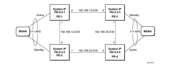
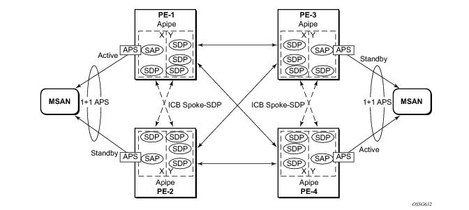
The setup in this section contains two access nodes and 4 PE nodes. The access nodes can be any ATM switches that support 1+1 bi-directional APS. Figure 18 shows the physical topology of the setup.
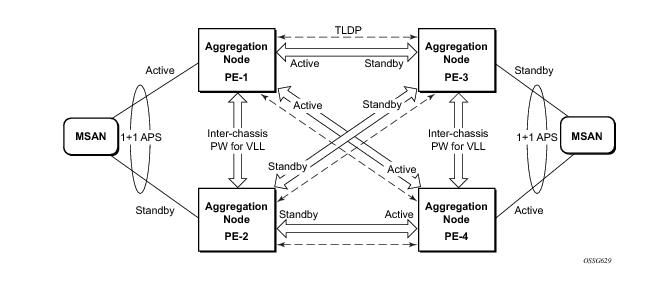
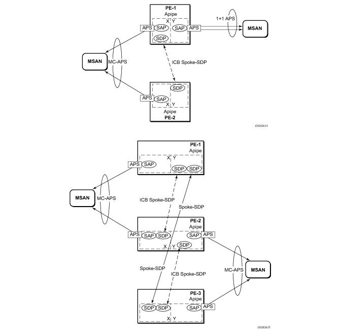
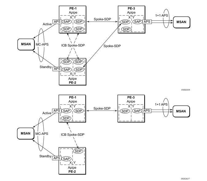
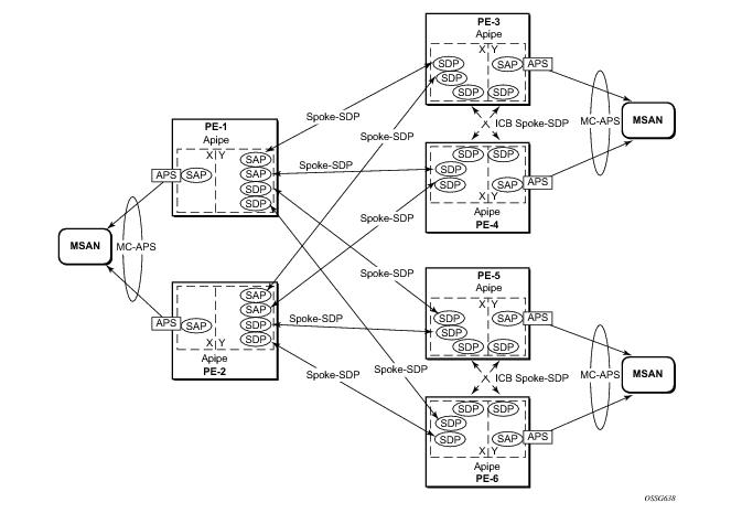
Figure 19 shows the use of both MC-APS in the access network and pseudowire redundancy in the core network to provide a resilient end-to-end VLL service.
A:PE-1# show router route-table
===============================================================================
Route Table (Router: Base)
===============================================================================
Dest Prefix Type Proto Age Pref
Next Hop[Interface Name] Metric
-------------------------------------------------------------------------------
192.0.2.1/32 Local Local 00h40m53s 0
system 0
192.0.2.2/32 Remote OSPF 00h41m57s 10
192.168.12.2 100
192.0.2.3/32 Remote OSPF 00h40m12s 10
192.168.13.2 100
192.0.2.4/32 Remote OSPF 00h42m53s 10
192.168.12.2 100
192.168.12.0/30 Local Local 00h43m15s 0
int-pe1-pe2 0
192.168.13.0/30 Local Local 00h42m10s 0
int-pe1-pe3 0
192.168.24.0/30 Remote OSPF 00h43m50s 10
192.168.12.2 200
192.168.34.0/30 Remote OSPF 00h42m51s 10
192.168.13.2 200
-------------------------------------------------------------------------------
No. of Routes: 8
===============================================================================
*A:PE-1#
A:PE-1# show service sdp
==============================================================================
Services: Service Destination Points
==============================================================================
SdpId Adm MTU Opr MTU IP address Adm Opr Deliver Signal
------------------------------------------------------------------------------
12 0 1556 192.0.2.2 Up Up LDP TLDP
13 0 1556 192.0.2.3 Up Up LDP TLDP
14 0 1556 192.0.2.4 Up Up LDP TLDP
------------------------------------------------------------------------------
Number of SDPs : 3
-------------------------------------------------------------------------------
===============================================================================
*A:PE-1#
Alcatel[RW]> configure
Alcatel[RW]> port 1-6-1-1
Alcatel[RW]> options protection type 1+1
Alcatel[RW]> options protection switching bidirect
Alcatel[RW]> options protection
(Standby)
# Type Status Name
1-6-1-1 STM1_IR8 OK
Protection Group Contains:
Protection Port : 1-6-1-1 (Standby)
Working Port : 1-5-1-1
Protection Type : 1+1
Switching Type : Non-Revertive
Switching Mode : Bi-directional
Wait-To-Restore Timer : 5 minute(s)
*A:PE-1>config>port 2/1/1# info
----------------------------------------------
sonet-sdh
exit
no shutdown----------------------------------------------
*A:PE-1>config>port 2/1/1#
*A:PE-1>config>port aps-1# info
----------------------------------------------
aps
neighbor 192.0.2.2
working-circuit 2/1/1
exit
sonet-sdh
path
atm
exit
no shutdown
exit
exit
no shutdown
----------------------------------------------
*A:PE-1>config>port aps-1#
*A:PE-2>config>port 2/1/1# info
----------------------------------------------
sonet-sdh
exit
no shutdown----------------------------------------------
*A:PE-2>config>port 2/1/1#
*A:PE-2>config>port aps-1# info
----------------------------------------------
aps
neighbor 192.0.2.1
protect-circuit 2/1/1
exit
sonet-sdh
path
atm
exit
no shutdown
exit
exit
no shutdown
----------------------------------------------
*A:PE-2>config>port aps-1#
*A:PE-1# show port aps-1
===============================================================================
SONET/SDH Interface
===============================================================================
Description : APS Group
Interface : aps-1 Speed : oc3
Admin Status : up Oper Status : up
Physical Link : Yes Loopback Mode : none
Single Fiber Mode : No
Clock Source : node Framing : sonet
Last State Change : 09/08/2010 12:37:42 Port IfIndex : 1358987264
Last Cleared Time : N/A
J0 String : 0x01 Section Trace Mode : byte
Rx S1 Byte : 0x00 Rx K1/K2 Byte : 0x00/0x00
Rx J0 String (Hex) : 81 00 00 00 00 00 00 00 00 00 00 00 00 00 00 00
Cfg Alarm : loc lais lrdi ss1f lb2er-sd lb2er-sf slof slos lrei
Alarm Status :
Hold time up : 500 milliseconds
Hold time down : 200 milliseconds
===============================================================================
Port Statistics
===============================================================================
Input Output
-------------------------------------------------------------------------------
Packets 8671498 4814981
Discards 0 0
Unknown Proto Discards 0
===============================================================================
*A:PE-1#
*A:PE-1# show aps detail
===============================================================================
APS Group: aps-1
===============================================================================
Description : APS Group
Group Id : 1 Active Circuit : 2/1/1
Admin Status : Up Oper Status : Up
Working Circuit : 2/1/1 Protection Circuit : N/A
Switching-mode : Bi-directional Switching-arch : 1+1
Revertive-mode : Non-revertive Revert-time (min) :
Rx K1/K2 byte : N/A
Tx K1/K2 byte : N/A
Current APS Status : OK
Multi-Chassis APS : Yes
Neighbor : 192.0.2.2
Control link state : Up
Advertise Interval : 1000 msec Hold time : 3000 msec
Mode mismatch Cnt : 0 Channel mismatch Cnt : 0
PSB failure Cnt : 0 FEPL failure Cnt : 0
-------------------------------------------------------------------------------
APS Working Circuit - 2/1/1
-------------------------------------------------------------------------------
Admin Status : Up Oper Status : Up
Current APS Status : OK No. of Switchovers : 0
Last Switchover : None Switchover seconds : 0
Signal Degrade Cnt : 1 Signal Failure Cnt : 0
Last Switch Cmd : N/A Last Exercise Result : N/A
Tx L-AIS : None
===============================================================================
*A:PE-1#
*A:PE-2# show aps detail
===============================================================================
APS Group: aps-1
===============================================================================
Description : APS Group
Group Id : 1 Active Circuit : N/A
Admin Status : Up Oper Status : Up
Working Circuit : N/A Protection Circuit : 1/2/1
Switching-mode : Bi-directional Switching-arch : 1+1
Revertive-mode : Non-revertive Revert-time (min) :
Rx K1/K2 byte : 0x00/0x05 (No-Req on Protect)
Tx K1/K2 byte : 0x00/0x05 (No-Req on Protect)
Current APS Status : OK
Multi-Chassis APS : Yes
Neighbor : 192.0.2.1
Control link state : Up
Advertise Interval : 1000 msec Hold time : 3000 msec
Mode mismatch Cnt : 0 Channel mismatch Cnt : 0
PSB failure Cnt : 0 FEPL failure Cnt : 1
-------------------------------------------------------------------------------
APS Working Circuit - Neighbor
-------------------------------------------------------------------------------
Admin Status : N/A Oper Status : N/A
Current APS Status : OK No. of Switchovers : 0
Last Switchover : None Switchover seconds : 0
Signal Degrade Cnt : 1 Signal Failure Cnt : 1
Last Switch Cmd : No Cmd Last Exercise Result : Unknown
Tx L-AIS : None
-------------------------------------------------------------------------------
APS Protection Circuit - 1/2/1
-------------------------------------------------------------------------------
Admin Status : Up Oper Status : Up
Current APS Status : OK No. of Switchovers : 0
Last Switchover : None Switchover seconds : 0
Signal Degrade Cnt : 1 Signal Failure Cnt : 0
Last Switch Cmd : No Cmd Last Exercise Result : Unknown
Tx L-AIS : None
===============================================================================
*A:PE-2
*A:PE-1>config>service>apipe# info
----------------------------------------------
endpoint "x" create
exit
endpoint "y" create
exit
sap aps-1:0/32 endpoint "x" create
exit
spoke-sdp 13:1 endpoint "y" create
exit
spoke-sdp 14:1 endpoint "y" create
exit
no shutdown
----------------------------------------------
*A:PE-1>config>service>apipe#
*A:PE-1# show service service-using
===============================================================================
Services
===============================================================================
ServiceId Type Adm Opr CustomerId Last Mgmt Change
-------------------------------------------------------------------------------
1000 Apipe Up Up 1 08/09/2010 09:55:23
-------------------------------------------------------------------------------
Matching Services : 1
-------------------------------------------------------------------------------
===============================================================================
*A:PE-1#
*A:PE-2# show service service-using
===============================================================================
Services
===============================================================================
ServiceId Type Adm Opr CustomerId Last Mgmt Change
-------------------------------------------------------------------------------
1000 Apipe Up Down 1 08/09/2010 09:55:55
-------------------------------------------------------------------------------
Matching Services : 1
-------------------------------------------------------------------------------
===============================================================================
*A:PE-2#
*A:PE-3# show service service-using
===============================================================================
Services
===============================================================================
ServiceId Type Adm Opr CustomerId Last Mgmt Change
-------------------------------------------------------------------------------
1000 Apipe Up Down 1 08/09/2010 09:56:12
-------------------------------------------------------------------------------
Matching Services : 1
-------------------------------------------------------------------------------
===============================================================================
*A:PE-3#
*A:PE-4# show service service-using
===============================================================================
Services
===============================================================================
ServiceId Type Adm Opr CustomerId Last Mgmt Change
-------------------------------------------------------------------------------
1000 Apipe Up Up 1 08/09/2010 09:56:45
-------------------------------------------------------------------------------
Matching Services : 1
-------------------------------------------------------------------------------
===============================================================================
*A:PE-4#
*A:PE-2# show service id 1 sdp 23:1 detail
===============================================================================
Service Destination Point (Sdp Id : 23:1) Details
===============================================================================
-------------------------------------------------------------------------------
Sdp Id 23:1 -(192.0.2.3)
-------------------------------------------------------------------------------
Description : (Not Specified)
SDP Id :23:1 Type : Spoke
Split Horiz Grp : (Not Specified)
VC Type : Ether VC Tag : n/a
Admin Path MTU : 0 Oper Path MTU : 1556
Far End : 192.0.2.3 Delivery : LDP
Admin State : Up Oper State : Up
Acct. Pol : None Collect Stats : Disabled
Ingress Label : 131070 Egress Label : 131070
Ingr Mac Fltr : n/a Egr Mac Fltr : n/a
Ingr ip Fltr : n/a Egr ip Fltr : n/a
Ingr ipv6 Fltr : n/a Egr ipv6 Fltr : n/a
Admin ControlWord : Not Preferred Oper ControlWord : False
Admin BW(Kbps) : 0 Oper BW(Kbps) : 0
Last Status Change : 08/09/2010 15:13:15 Signaling : TLDP
Last Mgmt Change : 08/07/2010 09:41:08 Force Vlan-Vc : Disabled
Endpoint : y Precedence : 4
Class Fwding State : Down
Flags : None
Peer Pw Bits : lacIngressFault lacEgressFault pwFwdingStandby
Peer Fault Ip : None
Peer Vccv CV Bits : lspPing
Peer Vccv CC Bits : mplsRouterAlertLabel
KeepAlive Information :
Admin State : Disabled Oper State : Disabled
Hello Time : 10 Hello Msg Len : 0
Max Drop Count : 3 Hold Down Time : 10
Statistics :
I. Fwd. Pkts. : 0 I. Dro. Pkts. : 0
E. Fwd. Pkts. : 0 E. Fwd. Octets : 0
-------------------------------------------------------------------------------
Number of SDPs : 1
-------------------------------------------------------------------------------
===============================================================================
*A:PE-2#
*A:PE-1>config>service>apipe# info
----------------------------------------------
endpoint "x" create
exit
endpoint "y" create
exit
sap aps-1:0/32 endpoint "x" create
exit
spoke-sdp 13:1 endpoint "y" create
exit
spoke-sdp 14:1 endpoint "y" create
exit
spoke-sdp 12:1 endpoint "x" icb create
exit
spoke-sdp 12:2 endpoint "y" icb create
exit
no shutdown
----------------------------------------------
*A:PE-1>config>service>apipe
*A:PE-2>config>service>apipe# info
----------------------------------------------
endpoint "x" create
exit
endpoint "y" create
exit
sap aps-1:0/32 endpoint "x" create
exit
spoke-sdp 23:1 endpoint "y" create
exit
spoke-sdp 24:1 endpoint "y" create
exit
spoke-sdp 21:1 endpoint "y" icb create
exit
spoke-sdp 21:2 endpoint "x" icb create
exit
no shutdown
----------------------------------------------
*A:PE-2>config>service>apipe#
*A:PE-3>config>service>apipe# info
----------------------------------------------
endpoint "x" create
exit
endpoint "y" create
exit
sap aps-1:0/32 endpoint "y" create
exit
spoke-sdp 31:1 endpoint "x" create
exit
spoke-sdp 32:1 endpoint "x" create
exit
spoke-sdp 34:1 endpoint "x" icb create
exit
spoke-sdp 34:2 endpoint "y" icb create
exit
no shutdown
----------------------------------------------
*A:PE-3>config>service>apipe#
*A:PE-4>config>service>apipe# info
----------------------------------------------
endpoint "x" create
exit
endpoint "y" create
exit
sap aps-1:0/32 endpoint "y" create
exit
spoke-sdp 41:1 endpoint "x" create
exit
spoke-sdp 42:1 endpoint "x" create
exit
spoke-sdp 43:1 endpoint "y" icb create
exit
spoke-sdp 43:2 endpoint "x" icb create
exit
no shutdown
----------------------------------------------
*A:PE-4>config>service>apipe#
*A:PE-1# show service id 1000 endpoint
-------------------------------------------------------------------------------
Service Endpoints
-------------------------------------------------------------------------------
Endpoint name : x
Revert time : 0
Act Hold Delay : 0
Ignore Standby Signaling : false
Suppress Standby Signaling : true
Tx Active : aps-1:0/32
Tx Active Up Time : 0d 02:01:19
Revert Time Count Down : N/A
Tx Active Change Count : 8
Last Tx Active Change : 08/09/2010 02:24:18
-------------------------------------------------------------------------------
Members
-------------------------------------------------------------------------------
SAP : aps-1:0/32
Spoke-sdp : 12:1 Precedence:4 (icb)
===============================================================================
Endpoint name : y
Revert time : 0
Act Hold Delay : 0
Ignore Standby Signaling : false
Suppress Standby Signaling : true
Tx Active : 14:1
Tx Active Up Time : 0d 03:16:08
Revert Time Count Down : N/A
Tx Active Change Count : 1
Last Tx Active Change : 08/09/2010 02:23:18
-------------------------------------------------------------------------------
Members
-------------------------------------------------------------------------------
Spoke-sdp : 12:2 Precedence:4 (icb)
Spoke-sdp : 13:1 Precedence:4
Spoke-sdp : 14:1 Precedence:4
===============================================================================
*A:PE-1#
*A:PE-1# tools perform aps force
- force <aps-id> {protect|working}
<aps-id> : aps-<group-id>
aps - keyword
group-id - [1..64]
<protect|working> : keyword
*A:PE1# tools perform aps clear
- clear <aps-id> {protect|working}
<aps-id> : aps-<group-id>
aps - keyword
group-id - [1..64]
<protect|working> : protect|working