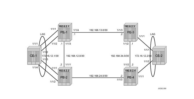
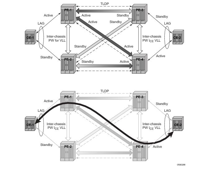
Figure 26 shows the use of both MC-LAG in the access network and pseudowire redundancy in the core network to provide a resilient end-to-end VLL service between CE1 and CE2.
Note in Figure 26 that when an SDP is in standby it sends the pseudowire status bit pwFwdingStandby to its peer.
*A:PE-1# show router route-table
===============================================================================
Route Table (Router: Base)
===============================================================================
Dest Prefix Type Proto Age Pref
Next Hop[Interface Name] Metric
-------------------------------------------------------------------------------
192.0.2.1/32 Local Local 00h29m42s 0
system 0
192.0.2.2/32 Remote OSPF 00h28m37s 10
192.168.12.2 100
192.0.2.3/32 Remote OSPF 00h27m53s 10
192.168.13.2 100
192.0.2.4/32 Remote OSPF 00h27m02s 10
192.168.12.2 200
192.168.12.0/30 Local Local 00h29m42s 0
int-PE-1-PE-2 0
192.168.13.0/30 Local Local 00h29m42s 0
int-PE-1-PE-3 0
192.168.24.0/30 Remote OSPF 00h28m37s 10
192.168.12.2 200
192.168.34.0/30 Remote OSPF 00h27m53s 10
192.168.13.2 200
-------------------------------------------------------------------------------
No. of Routes: 8
===============================================================================
*A:PE-1#
*A:PE-1# show service sdp
===============================================================================
Services: Service Destination Points
===============================================================================
SdpId Adm MTU Opr MTU IP address Adm Opr Deliver Signal
-------------------------------------------------------------------------------
12 0 1556 192.0.2.2 Up Up LDP TLDP
13 0 1556 192.0.2.3 Up Up LDP TLDP
14 0 1556 192.0.2.4 Up Up LDP TLDP
-------------------------------------------------------------------------------
Number of SDPs : 3
-------------------------------------------------------------------------------
===============================================================================
*A:PE-1#
*A:CE1# configure port 1/1/[1..4] ethernet autonegotiate limited
*A:CE1# configure port 1/1/[1..4] no shut
*A:CE1# configure lag 1 port 1/1/1 1/1/2 1/1/3 1/1/4
*A:CE1# configure lag 1 lacp active
*A:CE1# configure lag 1 no shutdown
*A:PE1# configure port 1/1/[1..2] ethernet autonegotiate limited
*A:PE1# configure port 1/1/[1..2] ethernet mode access
*A:PE1# configure port 1/1/[1..2] no shut
*A:PE1# configure lag 1 mode access
*A:PE1# configure lag 1 port 1/1/1 1/1/2
*A:PE1# configure lag 1 lacp active
*A:PE1# configure lag 1 no shutdown
*A:PE-1>config>redundancy>multi-chassis# info
----------------------------------------------
peer 192.0.2.2 create
authentication-key "441dO/0RgDhHgzYwpOCTK9zbKjv4GZ/z" hash2
mc-lag
lag 1 lacp-key 1 system-id 00:00:00:00:00:01 system-priority 100
no shutdown
exit
no shutdown
exit
----------------------------------------------
*A:PE-1>config>redundancy>multi-chassis#
*A:PE-2>config>redundancy>multi-chassis# info
----------------------------------------------
peer 192.0.2.1 create
authentication-key "441dO/0RgDg2CA0JlyzVNQBoRc327b1j" hash2
mc-lag
lag 1 lacp-key 1 system-id 00:00:00:00:00:01 system-priority 100
no shutdown
exit
no shutdown
exit
----------------------------------------------
*A:PE-2>config>redundancy>multi-chassis#
*A:PE-1# show redundancy multi-chassis sync
===============================================================================
Multi-chassis Peer Table
===============================================================================
Peer
-------------------------------------------------------------------------------
Peer IP Address : 192.0.2.2
Description : (Not Specified)
Authentication : Enabled
Source IP Address : 192.0.2.1
Admin State : Enabled
-------------------------------------------------------------------------------
Sync: Not-configured
-------------------------------------------------------------------------------
===============================================================================
*A:PE-1#
*A:PE-1# show redundancy multi-chassis mc-lag peer 192.0.2.2
===============================================================================
Multi-Chassis MC-Lag Peer 192.0.2.2
===============================================================================
Last State chg : 11/01/2009 11:07:48
Admin State : Up Oper State : Up
KeepAlive : 10 deci-seconds Hold On Ngbr Failure : 3
-------------------------------------------------------------------------------
Lag Id Lacp Key Remote Lag Id System Id Sys Prio Last State Changed
-------------------------------------------------------------------------------
1 1 1 00:00:00:00:00:01 100 11/01/2009 11:06:08
-------------------------------------------------------------------------------
Number of LAGs : 1
===============================================================================
*A:PE-1#
Note that there is a fixed keepalive timer of 1 second. The hold-on-neighbor-failure multiplier command indicates the interval that the standby node will wait for packets from the active node before assuming a redundant-neighbor failure. The
hold-on-neighbor-failure multiplier command is configurable (2-25) in the
config>redundancy>multi-chassis>peer>mc-lag context. The standby node will also assume a redundant-neighbor failure when there is no route available to the redundant-neighbor.
In this example the lag-id is 1 on both redundant PEs. This is not mandatory. If the
lag-id on PE-2 is, for example 2, the following should be configured on PE-1:
*A:PE-1# configure redundancy multi-chassis
*A:PE-1>config>redundancy>multi-chassis# peer 192.0.2.2 mc-lag lag 1 remote-lag 2 lacp-key 1 system-id 00:00:00:00:00:01 system-priority 100
*A:PE-1# show lag 1
===============================================================================
Lag Data
===============================================================================
Lag-id Adm Opr Port-Threshold Up-Link-Count MC Act/Stdby
-------------------------------------------------------------------------------
1 up up 0 2 active
===============================================================================
*A:PE-1#
*A:PE-2# show lag 1
===============================================================================
Lag Data
===============================================================================
Lag-id Adm Opr Port-Threshold Up-Link-Count MC Act/Stdby
-------------------------------------------------------------------------------
1 up down 0 0 standby
===============================================================================
*A:PE-2#
*A:PE1# configure lag 1 port 1/1/1 1/1/2 priority 10
*A:PE-1# show lag 1 detail
===============================================================================
LAG Details
===============================================================================
Description : N/A
-------------------------------------------------------------------------------
Details
-------------------------------------------------------------------------------
Lag-id : 1 Mode : access
Adm : up Opr : up
Thres. Exceeded Cnt : 1 Port Threshold : 0
Thres. Last Cleared : 11/01/2009 11:06:10 Threshold Action : down
Dynamic Cost : false Encap Type : null
Configured Address : 1e:51:ff:00:01:41 Lag-IfIndex : 1342177281
Hardware Address : 1e:51:ff:00:01:41 Adapt Qos : distribute
Hold-time Down : 0.0 sec Port Type : standard
Per FP Ing Queuing : disabled
LACP : enabled Mode : active
LACP Transmit Intvl : fast LACP xmit stdby : enabled
Selection Criteria : highest-count Slave-to-partner : disabled
Number of sub-groups: 1 Forced : -
System Id : 1e:51:ff:00:00:00 System Priority : 32768
Admin Key : 32768 Oper Key : 1
Prtr System Id : 1e:50:ff:00:00:00 Prtr System Priority : 32768
Prtr Oper Key : 32768
MC Peer Address : 192.0.2.2 MC Peer Lag-id : 1
MC System Id : 00:00:00:00:00:01 MC System Priority : 100
MC Admin Key : 1 MC Active/Standby : active
MC Lacp ID in use : true MC extended timeout : false
MC Selection Logic : peer decided
MC Config Mismatch : no mismatch
-------------------------------------------------------------------------------
Port-id Adm Act/Stdby Opr Primary Sub-group Forced Prio
-------------------------------------------------------------------------------
1/1/1 up active up yes 1 - 10
1/1/2 up active up 1 - 10
-------------------------------------------------------------------------------
Port-id Role Exp Def Dist Col Syn Aggr Timeout Activity
-------------------------------------------------------------------------------
1/1/1 actor No No Yes Yes Yes Yes Yes Yes
1/1/1 partner No No Yes Yes Yes Yes Yes Yes
1/1/2 actor No No Yes Yes Yes Yes Yes Yes
1/1/2 partner No No Yes Yes Yes Yes Yes Yes
===============================================================================
*A:PE-1#
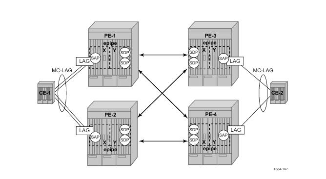
Configure an Epipe service on every PE and create endpoints x and
y (the endpoint names can be any text string). Traffic can only be forwarded between two endpoints, for example, it is not possible for objects associated with the same endpoint to forward traffic to each other.
*A:PE-1>config>service>epipe# info
----------------------------------------------
endpoint "x" create
exit
endpoint "y" create
exit
sap lag-1 endpoint "x" create
exit
spoke-sdp 13:1 endpoint "y" create
exit
spoke-sdp 14:1 endpoint "y" create
exit
no shutdown
----------------------------------------------
*A:PE-1>config>service>epipe#
*A:PE-1# show service service-using
===============================================================================
Services
===============================================================================
ServiceId Type Adm Opr CustomerId Last Mgmt Change
-------------------------------------------------------------------------------
1 Epipe Up Up 1 11/01/2009 11:55:13
-------------------------------------------------------------------------------
Matching Services : 1
-------------------------------------------------------------------------------
===============================================================================
*A:PE-1#
*A:PE-2# show service service-using
===============================================================================
Services
===============================================================================
ServiceId Type Adm Opr CustomerId Last Mgmt Change
-------------------------------------------------------------------------------
1 Epipe Up Down 1 11/01/2009 11:55:38
-------------------------------------------------------------------------------
Matching Services : 1
-------------------------------------------------------------------------------
==============================================================================
*A:PE-2#
*A:PE-3# show service service-using
===============================================================================
Services
===============================================================================
ServiceId Type Adm Opr CustomerId Last Mgmt Change
-------------------------------------------------------------------------------
1 Epipe Up Down 1 11/01/2009 10:56:10
-------------------------------------------------------------------------------
Matching Services : 1
-------------------------------------------------------------------------------
===============================================================================
*A:PE-3#
*A:PE-4# show service service-using
===============================================================================
Services
===============================================================================
ServiceId Type Adm Opr CustomerId Last Mgmt Change
-------------------------------------------------------------------------------
1 Epipe Up Up 1 11/01/2009 11:01:07
-------------------------------------------------------------------------------
Matching Services : 1
-------------------------------------------------------------------------------
===============================================================================
*A:PE-4#
The Epipe service on PE-2 and PE-3 is down and up on PE-1 and PE-4. This reflects the standby behavior shown in Figure 26. Note that after configuring ICB spoke SDPs (described later in this document) the Epipe will be in up/up status on all PE routers.
*A:PE-2# show service id 1 sdp 23:1 detail
===============================================================================
Service Destination Point (Sdp Id : 23:1) Details
===============================================================================
-------------------------------------------------------------------------------
Sdp Id 23:1 -(192.0.2.3)
-------------------------------------------------------------------------------
Description : (Not Specified)
SDP Id : 23:1 Type : Spoke
Split Horiz Grp : (Not Specified)
VC Type : Ether VC Tag : n/a
Admin Path MTU : 0 Oper Path MTU : 1556
Far End : 192.0.2.3 Delivery : LDP
Admin State : Up Oper State : Up
Acct. Pol : None Collect Stats : Disabled
Ingress Label : 131070 Egress Label : 131070
Ing mac Fltr : n/a Egr mac Fltr : n/a
Ing ip Fltr : n/a Egr ip Fltr : n/a
Ing ipv6 Fltr : n/a Egr ipv6 Fltr : n/a
Admin ControlWord : Not Preferred Oper ControlWord : False
Admin BW(Kbps) : 0 Oper BW(Kbps) : 0
Last Status Change : 11/01/2009 11:01:50 Signaling : TLDP
Last Mgmt Change : 10/29/2009 17:14:13 Force Vlan-Vc : Disabled
Endpoint : y Precedence : 4
Class Fwding State : Down
Flags : None
Peer Pw Bits : lacIngressFault lacEgressFault pwFwdingStandby
Peer Fault Ip : None
Peer Vccv CV Bits : lspPing
Peer Vccv CC Bits : mplsRouterAlertLabel
KeepAlive Information :
Admin State : Disabled Oper State : Disabled
Hello Time : 10 Hello Msg Len : 0
Max Drop Count : 3 Hold Down Time : 10
Statistics :
I. Fwd. Pkts. : 0 I. Dro. Pkts. : 0
E. Fwd. Pkts. : 0 E. Fwd. Octets : 0
-------------------------------------------------------------------------------
Number of SDPs : 1
-------------------------------------------------------------------------------
===============================================================================
*A:PE-2#
In case of revertive behavior MC-LAG convergence might take less time than the setup of the spoke SDPs, thus creating a temporary blackhole. To avoid this situation it’s best to configure hold-time up on the LAG ports. In that case the ports are kept in a down state for a configured period of time after the node has rebooted. This is done to ensure that the SDPs are operationally up when the MC-LAG convergence takes place.
hold-time up is expressed in seconds.
*A:PE-1# configure port 1/1/1 ethernet hold-time up 50
*A:PE-1# configure port 1/1/2 ethernet hold-time up 50
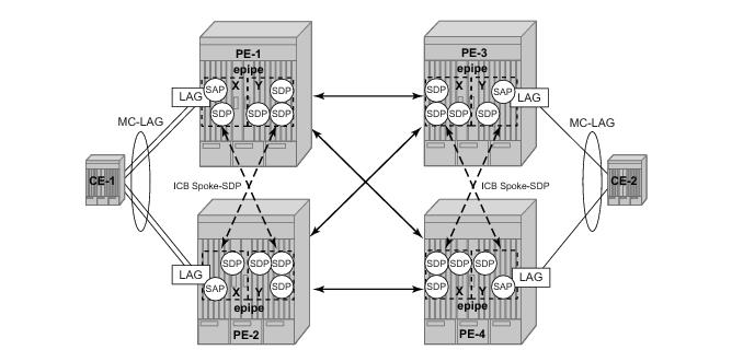
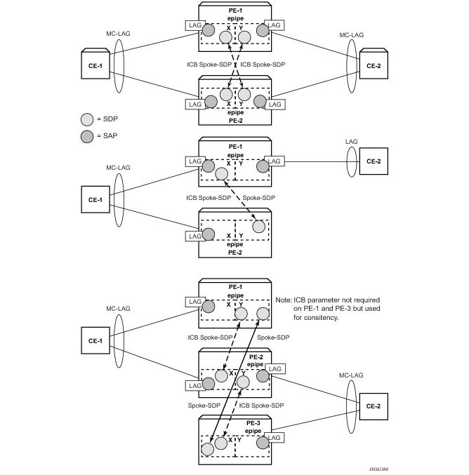
Note that in this setup the configuration of ICBs is optional. It can be used to speed up convergence by forwarding in-flight packets during MC-LAG transition. Figure 29 shows some setup examples where ICBs are required. ICBs cannot be configured at endpoints where the other object is a standard SAP, only MC-LAG SAPs and pseudowires are allowed with ICBs.
The ICB spoke SDPs must cross, one end should be associated with endpoint x and the other end (on the other PE) should be associated with endpoint
y. Note that after configuring the ICB spoke SDPs the Epipe service will be up/up on all four PE routers.
*A:PE-1>config>service>epipe# info
----------------------------------------------
endpoint "x" create
exit
endpoint "y" create
exit
sap lag-1 endpoint "x" create
exit
spoke-sdp 13:1 endpoint "y" create
exit
spoke-sdp 14:1 endpoint "y" create
exit
spoke-sdp 12:1 endpoint "x" icb create
exit
spoke-sdp 12:2 endpoint "y" icb create
exit
no shutdown
----------------------------------------------
*A:PE-1>config>service>epipe
*A:PE-2>config>service>epipe# info
----------------------------------------------
endpoint "x" create
exit
endpoint "y" create
exit
sap lag-1 endpoint "x" create
exit
spoke-sdp 23:1 endpoint "y" create
exit
spoke-sdp 24:1 endpoint "y" create
exit
spoke-sdp 21:1 endpoint "y" icb create
exit
spoke-sdp 21:2 endpoint "x" icb create
exit
no shutdown
----------------------------------------------
*A:PE-2>config>service>epipe#
*A:PE-3>config>service>epipe# info
----------------------------------------------
endpoint "x" create
exit
endpoint "y" create
exit
sap lag-1 endpoint "y" create
exit
spoke-sdp 31:1 endpoint "x" create
exit
spoke-sdp 32:1 endpoint "x" create
exit
spoke-sdp 34:1 endpoint "x" icb create
exit
spoke-sdp 34:2 endpoint "y" icb create
exit
no shutdown
----------------------------------------------
*A:PE-3>config>service>epipe#
*A:PE-4>config>service>epipe# info
----------------------------------------------
endpoint "x" create
exit
endpoint "y" create
exit
sap lag-1 endpoint "y" create
exit
spoke-sdp 41:1 endpoint "x" create
exit
spoke-sdp 42:1 endpoint "x" create
exit
spoke-sdp 43:1 endpoint "y" icb create
exit
spoke-sdp 43:2 endpoint "x" icb create
exit
no shutdown
----------------------------------------------
*A:PE-4>config>service>epipe#
*A:PE-1# show service id 1 endpoint
===============================================================================
Service 1 endpoints
===============================================================================
Endpoint name : x
Description : (Not Specified)
Revert time : 0
Act Hold Delay : 0
Ignore Standby Signaling : false
Suppress Standby Signaling : true
Block On Mesh Fail : false
Tx Active : lag-1
Tx Active Up Time : 0d 01:30:25
Revert Time Count Down : N/A
Tx Active Change Count : 2
Last Tx Active Change : 11/01/2009 11:06:10
-------------------------------------------------------------------------------
Members
-------------------------------------------------------------------------------
SAP : lag-1 Oper Status: Up
Spoke-sdp: 12:1 Prec:4 (icb) Oper Status: Up
===============================================================================
Endpoint name : y
Description : (Not Specified)
Revert time : 0
Act Hold Delay : 0
Ignore Standby Signaling : false
Suppress Standby Signaling : true
Block On Mesh Fail : false
Tx Active : 14:1
Tx Active Up Time : 0d 01:30:48
Revert Time Count Down : N/A
Tx Active Change Count : 3
Last Tx Active Change : 11/01/2009 11:05:48
-------------------------------------------------------------------------------
Members
-------------------------------------------------------------------------------
Spoke-sdp: 12:2 Prec:4 (icb) Oper Status: Up
Spoke-sdp: 13:1 Prec:4 Oper Status: Up
Spoke-sdp: 14:1 Prec:4 Oper Status: Up
===============================================================================
*A:PE-1#
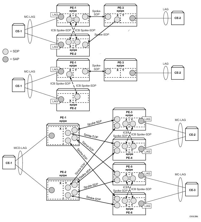
Figure 29 and
Figure 30 shows other setups that combine MC-LAG and pseudowire redundancy.
*A:PE-1# tools perform lag force
- force all-mc {active|standby}
- force lag-id <lag-id> [sub-group <sub-group-id>] {active|standby}
- force peer-mc <peer-ip-address> {active|standby}
<lag-id> : [1..200]
<sub-group-id> : [1..16]
<all-mc> : keyword
<peer-ip-address> : a.b.c.d
<active|standby> : keywords
*A:PE1# tools perform lag clear-force
- clear-force all-mc
- clear-force lag-id <lag-id> [sub-group <sub-group-id>]
- clear-force peer-mc <ip-address>
<lag-id> : [1..200]
<sub-group-id> : [1..16]
<all-mc> : keyword
<ip-address> : a.b.c.d