configure service
sdp 31 mpls create
far-end 192.0.2.1
ldp
keep-alive
shutdown
exit
no shutdown
exit
sdp 32 mpls create
far-end 192.0.2.2
ldp
keep-alive
shutdown
exit
no shutdown
exit
sdp 34 mpls create
far-end 192.0.2.4
ldp
keep-alive
shutdown
exit
no shutdown
exit
sdp 35 mpls create
far-end 192.0.2.5
ldp
keep-alive
shutdown
exit
no shutdown
exit
exit
A:PE-3# show service sdp
===============================================================================
Services: Service Destination Points
===============================================================================
SdpId Adm MTU Opr MTU IP address Adm Opr Deliver Signal
-------------------------------------------------------------------------------
31 0 1556 192.0.2.1 Up Up LDP TLDP
32 0 1556 192.0.2.2 Up Up LDP TLDP
34 0 1556 192.0.2.4 Up Up LDP TLDP
35 0 1556 192.0.2.5 Up Up LDP TLDP
-------------------------------------------------------------------------------
Number of SDPs : 4
-------------------------------------------------------------------------------
===============================================================================
A:PE-3#
configure service
vpls 1 customer 1 create
description "core VPLS"
stp
shutdown
exit
mesh-sdp 12:1 create
exit
no shutdown
exit
exit
configure service
description "Metro 1 VPLS"
vpls 2 customer 1 create
stp
shutdown
exit
mesh-sdp 34:2 create
exit
mesh-sdp 35:2 create
exit
no shutdown
exit
exit
configure service
description "Metro 2 VPLS"
vpls 3 customer 1 create
stp
shutdown
exit
mesh-sdp 67:3 create
exit
mesh-sdp 68:3 create
exit
no shutdown
exit
exit
A:PE-6# show service id 3 base
===============================================================================
Service Basic Information
===============================================================================
Service Id : 3 Vpn Id : 0
Service Type : VPLS
Description : (Not Specified)
Customer Id : 1
Last Status Change: 12/03/2009 14:05:31
Last Mgmt Change : 12/03/2009 14:05:17
Admin State : Up Oper State : Up
MTU : 1514 Def. Mesh VC Id : 3
SAP Count : 0 SDP Bind Count : 3
Snd Flush on Fail : Disabled Host Conn Verify : Disabled
Propagate MacFlush: Disabled
Def. Gateway IP : None
Def. Gateway MAC : None
-------------------------------------------------------------------------------
Service Access & Destination Points
-------------------------------------------------------------------------------
Identifier Type AdmMTU OprMTU Adm Opr
-------------------------------------------------------------------------------
sdp:67:3 M(192.0.2.7) n/a 0 1556 Up Up
sdp:68:3 M(192.0.2.8) n/a 0 1556 Up Up
===============================================================================
A:PE-6#
configure redundancy
multi-chassis
peer 192.0.2.4 create
mc-endpoint
no shutdown
exit
no shutdown
exit
exit
exit
A:PE-3# show redundancy multi-chassis mc-endpoint peer 192.0.2.4
===============================================================================
Multi-Chassis MC-Endpoint
===============================================================================
Peer Addr : 192.0.2.4 Peer Name :
Admin State : up Oper State : up
Last State chg : 12/03/2009 14:08:45 Source Addr : 0.0.0.0
System Id : 26:54:ff:00:00:00 Sys Priority : 0
Keep Alive Intvl: 10 Hold on Nbr Fail : 3
Passive Mode : disabled Psv Mode Oper : No
Boot Timer : 300 BFD : disabled
Last update : 12/08/2009 09:17:41 MC-EP Count : 1
===============================================================================
A:PE-3#
configure service
vpls 2 customer 1 create
endpoint "core" create
no suppress-standby-signaling
mc-endpoint 1
mc-ep-peer 192.0.2.4
exit
exit
exit
configure service
vpls 2 customer 1 create
spoke-sdp 31:1 endpoint "core" create
stp
shutdown
exit
precedence primary
exit
spoke-sdp 32:1 endpoint "core" create
stp
shutdown
exit
precedence 1
exit
exit
exit
A:PE-3# show service id 2 sdp
===============================================================================
Services: Service Destination Points
===============================================================================
SdpId Type IP address Adm Opr I.Lbl E.Lbl
-------------------------------------------------------------------------------
31:1 Spok 192.0.2.1 Up Up 131059 131062
32:1 Spok 192.0.2.2 Up Up 131064 131067
34:2 Mesh 192.0.2.4 Up Up 131068 131067
35:2 Mesh 192.0.2.5 Up Up 131063 131063
-------------------------------------------------------------------------------
Number of SDPs : 4
-------------------------------------------------------------------------------
===============================================================================
A:PE-3#
A:PE-3# show service id 2 endpoint core | match "Tx Active"
Tx Active : 31:1
Tx Active Up Time : 0d 00:03:04
Tx Active Change Count : 15
Last Tx Active Change : 12/08/2009 15:24:54
A:PE-4# show service id 2 endpoint | match "Tx Active"
Tx Active : none
Tx Active Up Time : 0d 00:00:00
Tx Active Change Count : 18
A:PE-1# show service id 1 sdp
===============================================================================
Services: Service Destination Points
===============================================================================
SdpId Type IP address Adm Opr I.Lbl E.Lbl
-------------------------------------------------------------------------------
12:1 Mesh 192.0.2.2 Up Up 131060 131060
13:1 Spok 192.0.2.3 Up Up 131062 131059
14:1 Spok 192.0.2.4 Up Up 131063 131060
-------------------------------------------------------------------------------
Number of SDPs : 3
-------------------------------------------------------------------------------
A:PE-1#
A:PE-1# show service id 1 sdp 13:1 detail | match "Peer Pw Bits"
Peer Pw Bits : None
A:PE-1# show service id 1 sdp 14:1 detail | match "Peer Pw Bits"
Peer Pw Bits : pwFwdingStandby
A:PE-2# show service id 1 sdp 23:1 detail | match "Peer Pw Bits"
Peer Pw Bits : pwFwdingStandby
A:PE-2# show service id 1 sdp 24:1 detail | match "Peer Pw Bits"
Peer Pw Bits : pwFwdingStandby
configure service
vpls 3 customer 1 create
endpoint "core" create
no suppress-standby-signaling
mc-endpoint 1
mc-ep-peer 192.0.2.6
exit
exit
exit
exit
configure service
vpls 3 customer 1 create
spoke SDP 72:1 endpoint "core" create
stp
shutdown
exit
precedence primary
exit
exit
exit
A:PE-7# show service id 3 sdp
===============================================================================
Services: Service Destination Points
===============================================================================
SdpId Type IP address Adm Opr I.Lbl E.Lbl
-------------------------------------------------------------------------------
72:1 Spok 192.0.2.2 Up Up 131063 131062
76:3 Mesh 192.0.2.6 Up Up 131062 131064
78:3 Mesh 192.0.2.8 Up Up 131068 131066
-------------------------------------------------------------------------------
Number of SDPs : 3
-------------------------------------------------------------------------------
===============================================================================
A:PE-7#
A:PE-7# show service id 3 endpoint | match "Tx Active"
Tx Active : 72:1
Tx Active Up Time : 0d 04:19:01
Tx Active Change Count : 3
Last Tx Active Change : 12/08/2009 11:02:10
A:PE-6# show service id 3 endpoint | match "Tx Active"
Tx Active : none
Tx Active Up Time : 0d 00:00:00
Tx Active Change Count : 2
Last Tx Active Change : 12/08/2009 11:17:31
A:PE-1# show service id 1 sdp 16:1 detail | match "Peer Pw Bits"
Peer Pw Bits : pwFwdingStandby
A:PE-2# show service id 1 sdp 27:1 detail | match "Peer Pw Bits"
Peer Pw Bits : None
A:PE-3# configure redundancy multi-chassis peer 192.0.2.4 mc-endpoint
[no] hold-on-neighb* - Configure hold time applied on neighbor failure
[no] keep-alive-int* - Configure keep alive interval for this MC-Endpoint
A:PE-3# configure redundancy multi-chassis peer 192.0.2.4 mc-endpoint
[no] bfd-enable - Configure BFD
configure router
interface "system"
address 192.0.2.3/32
bfd 100 receive 100 multiplier 3
exit
exit
A:PE-3# show router bfd session
===============================================================================
BFD Session
===============================================================================
Interface State Tx Intvl Rx Intvl Mult
Remote Address Protocol Tx Pkts Rx Pkts
-------------------------------------------------------------------------------
system Up (3) 100 100 3
192.0.2.4 mcep 65 65
-------------------------------------------------------------------------------
No. of BFD sessions: 1
===============================================================================
A:PE-3#
A:PE-3# configure redundancy multi-chassis peer 192.0.2.4 mc-endpoint
[no] boot-timer - Configure boot timer interval
The boot-timer command specifies the time after a reboot that the node will try to establish a connection with the MC peer before assuming a peer failure. In case of failure, the node will revert to single chassis behavior.
A:PE-3# configure redundancy multi-chassis peer 192.0.2.4 mc-endpoint
[no] system-priority - Configure system priority
A:PE-1# configure service vpls 1 spoke-sdp 14:1
ignore-standby-signaling
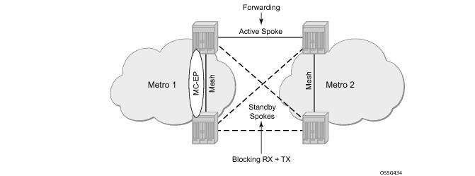
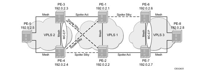
In this topology, if the ignore-standby-signaling command is enabled on PE-1, it sends MC traffic to PE-3 and PE-4 (and to PE-6). If PE-3 fails, PE-4 can start forwarding traffic in the VPLS as soon as it detects PE-3 being down. There is no signaling needed between PE-1 and PE-4.
A:PE-3# configure service vpls 2 endpoint core
block-on-mesh-failure
A:PE-3>config>service>vpls# info
----------------------------------------------
endpoint "core" create
exit
spoke-sdp 31:1 endpoint "core" create
precedence primary
exit
spoke-sdp 32:1 endpoint "core" create
precedence 1
exit
mesh-sdp 34:2 create
exit
mesh-sdp 35:2 create
exit
no shutdown
----------------------------------------------
A:PE-3>config>service>vpls# endpoint core block-on-mesh-failure
A:PE-3>config>service>vpls# info
----------------------------------------------
endpoint "core" create
block-on-mesh-failure
exit
spoke-sdp 31:1 endpoint "core" create
block-on-mesh-failure
precedence primary
exit
spoke-sdp 32:1 endpoint "core" create
block-on-mesh-failure
precedence 1
exit
mesh-sdp 34:2 create
exit
mesh-sdp 35:2 create
exit
no shutdown
----------------------------------------------
A:PE-3>config>service>vpls#
A:PE-3# configure service vpls 2 spoke-sdp 31:1
[no] precedence - Configure the spoke-sdp precendence
A:PE-3# configure service vpls 2 endpoint core
[no] revert-time - Configure the time to wait before reverting to primary
spoke-sdp
A node configured with propagate MAC flush will forward the flush messages received on the spoke-SDP to its other mesh/spoke SDPs.
A:PE-1# configure service vpls 1
propagate-mac-flush
A node configured with send flush on failure will send a
flush-all-from-me message when one of its SDPs goes down.
A:PE-1# configure service vpls 1
send-flush-on-failure
A:PE-3# show service id 2 endpoint
===============================================================================
Service 2 endpoints
===============================================================================
Endpoint name : core
Description : (Not Specified)
Revert time : 0
Act Hold Delay : 0
Ignore Standby Signaling : false
Suppress Standby Signaling : false
Block On Mesh Fail : false
Multi-Chassis Endpoint : 1
MC Endpoint Peer Addr : 192.0.2.4
Psv Mode Active : No
Tx Active : 32:1
Tx Active Up Time : 0d 00:01:45
Tx Active Change Count : 19
Last Tx Active Change : 12/08/2009 16:09:07
-------------------------------------------------------------------------------
Members
-------------------------------------------------------------------------------
Spoke-sdp: 31:1 Prec:0 Oper Status: Down
Spoke-sdp: 32:1 Prec:1 Oper Status: Up
===============================================================================
A:PE-3#
A:PE-4# show service id 2 endpoint
===============================================================================
Service 2 endpoints
===============================================================================
Endpoint name : core
Description : (Not Specified)
Revert time : 0
Act Hold Delay : 0
Ignore Standby Signaling : false
Suppress Standby Signaling : false
Block On Mesh Fail : false
Multi-Chassis Endpoint : 1
MC Endpoint Peer Addr : 192.0.2.3
Psv Mode Active : No
Tx Active : none
Tx Active Up Time : 0d 00:00:00
Tx Active Change Count : 21
Last Tx Active Change : 12/08/2009 16:08:12
-------------------------------------------------------------------------------
Members
-------------------------------------------------------------------------------
Spoke-sdp: 41:1 Prec:2 Oper Status: Down
Spoke-sdp: 42:1 Prec:3 Oper Status: Up
===============================================================================
A:PE-4#
A:PE-4# show redundancy multi-chassis mc-endpoint peer 192.0.2.3
===============================================================================
Multi-Chassis MC-Endpoint
===============================================================================
Peer Addr : 192.0.2.3 Peer Name :
Admin State : up Oper State : down
Last State chg : 12/08/2009 15:41:58 Source Addr : 0.0.0.0
System Id : 1e:28:ff:00:00:00 Sys Priority : 0
Keep Alive Intvl: 10 Hold on Nbr Fail : 3
Passive Mode : disabled Psv Mode Oper : No
Boot Timer : 300 BFD : disabled
Last update : 12/08/2009 15:05:08 MC-EP Count : 1
===============================================================================
A:PE-4#
A:PE-4# show service id 2 endpoint
===============================================================================
Service 2 endpoints
===============================================================================
Endpoint name : core
Description : (Not Specified)
Revert time : 0
Act Hold Delay : 0
Ignore Standby Signaling : false
Suppress Standby Signaling : false
Block On Mesh Fail : false
Multi-Chassis Endpoint : 1
MC Endpoint Peer Addr : 192.0.2.3
Psv Mode Active : No
Tx Active : 41:1
Tx Active Up Time : 0d 00:00:13
Tx Active Change Count : 19
Last Tx Active Change : 12/08/2009 15:41:58
-------------------------------------------------------------------------------
Members
-------------------------------------------------------------------------------
Spoke-sdp: 41:1 Prec:2 Oper Status: Up
Spoke-sdp: 42:1 Prec:3 Oper Status: Up
===============================================================================
A:PE-4#
A:PE-3# configure router
A:PE-3>config>router# static-route 192.0.2.4/32 black-hole
A:PE-4# show redundancy multi-chassis mc-endpoint peer 192.0.2.3
===============================================================================
Multi-Chassis MC-Endpoint
===============================================================================
Peer Addr : 192.0.2.3 Peer Name :
Admin State : up Oper State : down
Last State chg : 12/11/2009 15:12:25 Source Addr : 0.0.0.0
System Id : 1e:28:ff:00:00:00 Sys Priority : 0
Keep Alive Intvl: 10 Hold on Nbr Fail : 3
Passive Mode : disabled Psv Mode Oper : No
Boot Timer : 300 BFD : disabled
Last update : 12/08/2009 15:05:08 MC-EP Count : 1
===============================================================================
A:PE-4#
A:PE-3# show service id 2 endpoint | match "Tx Active"
Tx Active : 31:1
Tx Active Up Time : 1d 23:29:04
Tx Active Change Count : 20
Last Tx Active Change : 12/09/2009 15:50:22
A:PE-4# show service id 2 endpoint | match "Tx Active"
Tx Active : 42:1
Tx Active Up Time : 0d 00:06:27
Tx Active Change Count : 23
As in Multi-Chassis Communication Failure , if there is a failure in the multi-chassis communication, both nodes will assume that the peer is down and will revert to single-chassis mode. This can create loops because two spoke SDPs can become active.
The no suppress-standby-signaling and
no ignore-standby-signaling commands are required.
A:PE-1# configure redundancy
multi-chassis
peer 192.0.2.2 create
mc-endpoint
no shutdown
passive-mode
exit
no shutdown
exit
exit
A:PE-1# configure service vpls 1
endpoint "metro1" create
no suppress-standby-signaling
mc-endpoint 1
mc-ep-peer 192.0.2.2
exit
exit
spoke-sdp 13:1 endpoint "metro1" create
stp
shutdown
exit
exit
spoke-sdp 14:1 endpoint "metro1" create
stp
shutdown
exit
exit
A:PE-3# configure router
A:PE-3>config>router# static-route 192.0.2.4/32 black-hole
A:PE-3# show service id 2 endpoint | match "Tx Active"
Tx Active : 31:1
Tx Active Up Time : 1d 23:29:04
Tx Active Change Count : 20
Last Tx Active Change : 12/09/2009 15:50:22
A:PE-4# show service id 2 endpoint | match "Tx Active"
Tx Active : 42:1
Tx Active Up Time : 0d 00:06:27
Tx Active Change Count : 23
A:PE-1# show service id 1 endpoint metro1 | match "Tx Active"
Tx Active : none
Tx Active Up Time : 0d 00:00:00
Tx Active Change Count : 4
Last Tx Active Change : 12/11/2009 15:44:35
A:PE-2# show service id 1 endpoint metro1 | match "Tx Active"
Tx Active : 24:1
Tx Active Up Time : 0d 00:02:39
Tx Active Change Count : 1
Last Tx Active Change : 12/11/2009 15:44:35