For feedback and comments:
documentation.feedback@alcatel-lucent.com

Table of Contents Previous Next Index PDF


Multicast in a VPN I
In This Chapter
This section provides information about multicast in a VPRN service.
Topics in this section include:
Applicability
This section is applicable to all of the 7750 and 7710 SR series and was tested on release 7.0R5. There are no pre-requisites for this configuration. This is supported on 7450 ESS-7 or ESS-12 in mixed-mode since 8.0R1. The 7750 SR-c4 is supported from 8.0R4 and higher.
Summary
Multicast VPN (MVPN) architectures describe a set of VRFs that support the transport of multicast traffic across a provider network.
Draft-rosen-vpn-mcast-08.txt (herein referred to as Draft-Rosen) describes the use of multicast distribution trees (MDT) established between PEs within a given VRF. Each VRF required its own tree. Customer edge routers form Protocol Independent Multicast (PIM) adjacencies with the PE, and PE-PE PIM adjacencies are formed across the multicast tree. PIM signaling and data streams are transported across the MDT. There are a number of limitations with the Draft-Rosen implementation including, but not limited to:
Next Generation MVPN addresses these limitations by extending the idea of the per-VRF tree, by introducing the idea of Provider Multicast Service Interfaces (PMSI). These are equivalent to the default MDTs of Draft-Rosen in that they support control plane traffic (customer multicast signaling), and the data MDTs which carry multicast data traffic streams between PEs within a multicast VRF.
Next Generation MVPN allows the decoupling of the mechanism required to create a multicast VPN, such as PE auto-discovery (which PEs are members of which VPN), PMSI signaling (creation of tunnels between PEs) and customer multicast signaling (multicast signaling —IGMP/PIM — received from customer edge routers). Two types of PMSI exist:
Knowledge of MPLS-VPN RFC 4364, BGP/MPLS IP Virtual Private Networks (VPNs), architecture and functionality, as well as an understanding of multicast protocols, is assumed throughout.
 
This chapter provides configuration details required to implement the parts of Next Generation MVPN shown in Table 4.
 
The first section of this chapter describes the common configuration required for each PE within the provider multicast domain regardless of the MVPN PE auto-discovery or customer signaling methods. This includes IGP and VPRN service configuration.
Following the common configuration, specific MVPN configuration required for the configuration for the provider multicast domain using PIM Any Source Multicast (ASM) with auto-discovery based on PIM or BGP auto-discovery (A/D), PIM used for the customer multicast signaling and PIM Source Specific Multicast (SSM) used for the S-PMSI creation are described. The customer domain configuration covers the following three cases:
1.
2.
3.
Other possible options, not covered in this section but are discussed in the 7750 SR/7710 SR/7450 ESS OS Routing Protocols Guide:
The use of mLDP and RSVP p2mp LSPs for the I/S-PMSI was not available in release 7.0.
The Multicast in a VPRN II example in Multicast in a VPN II introduces features that were not supported in Release 7.0R5. It provides configuration details to implement:
 
References
 
Overview
Figure 91: Network Topology
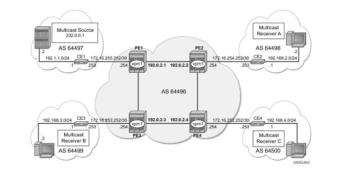
The network topology is displayed in Figure 91. The setup consists of four SR 7750s acting as Provider Edge (PE) routers within a single Autonomous System (AS).
Connected to each PE is a single 7750 acting as a Customer Edge (CE) router. CE-1 has a multicast sources connected, and PEs 2 to 4 each have a single receiver connected which will receive the multicast streams from the source. In this document, each receiver is both IGMPv2 and IGMPv3 capable. If the customer domain multicast signaling plane uses Source Specific Multicasting (SSM), then an IGMPv3 receiver is configured; if Any Source Multicasting (ASM) is used, the receiver is IGMPv2 capable.
If the receiver is IGMPv3 capable, it will issue IGMPv3 reports that will include a list of required source addresses. The receiver will join the 232.0.0.1 multicast group.
If the receiver is only IGMPv2 capable, then it will issue IGMPv2 reports which do not specify a source of the group. In this case a Rendezvous Point is required within the PIM control plane of the multicast VRF which is source-aware. In this case, the receiver will join the 225.0.0.1 multicast group.
When the receiver wishes to become a member of any group, the source address of the group must be known to the CE. As a result the source address must be IP reachable by each CE, so it is advertised by CE-1 to the PEs with attachment circuits in VPRN1 using BGP.
Static routes are then configured on the receiver CEs to achieve IP reachability to the source address of multicast groups. In the case of PIM ASM, any RP that is configured must also be reachable from the CE.
 
Multicast VPN Overview
Multicast traffic from the source is streamed towards router CE-1. Receivers connected to PE-2, PE-3 and PE-4 are interested in joining this multicast group.
CEs 1 to 4 are PIM enabled routers, which form a PIM adjacency with nearest PE. The PIM adjacencies between PEs across the Provider network are achieved using I-PMSIs. I-PMSIs carry PIM control messages between PEs. Data plane traffic is transported across the I-PMSI until a configured bandwidth threshold is reached. A Selective PMSI is then signaled that carries data plane traffic. This threshold can be as low as 1kb/second and must be explicitly configured along with the S-PMSI multicast group. An S-PMSI per customer group per VPRN is configured. If no S-PMSI and threshold is configured, data traffic will continue to be forwarded across the provider network within the I-PMSI.
 
Configuration
The configuration is divided into the following sections:
 
 
Provider Common Configuration
This section describes the common configuration required for each PE within the Provider multicast domain, regardless of the MVPN PE auto-discovery or customer signaling methods. This includes IGP and VPRN service configuration.
The configuration tasks can be summarized as follows:
 
PE Global Configuration
Step 1.
 
A:PE-1>config router
interface "int-pe1-pe2"
address 192.168.1.1/30
port 1/1/1
exit
interface "int-pe1-pe3"
address 192.168.2.1/30
port 1/1/2
exit
interface "system"
address 192.0.2.1/32
exit
autonomous-system 64496
ospf
area 0.0.0.0
interface "system"
exit
interface "int-pe1-pe2"
interface-type point-to-point
exit
interface "int-pe1-pe3"
interface-type point-to-point
exit
exit
exit
ldp
interface-parameters
interface "int-pe1-pe2"
exit
interface "int-pe1-pe3"
exit
exit
targeted-session
exit
exit
 
Step 2.
 
A:PE-1# show router ospf neighbor
===============================================================================
OSPF Neighbors
===============================================================================
Interface-Name Rtr Id State Pri RetxQ TTL
-------------------------------------------------------------------------------
int-pe1-pe2 192.0.2.2 Full 1 0 31
int-pe1-pe3 192.0.2.3 Full 1 0 37
-------------------------------------------------------------------------------
No. of Neighbors: 2
===============================================================================
 
 
A:PE-1 # show router ldp session
=============================================================================
LDP Sessions
=============================================================================
Peer LDP Id Adj Type State Msg Sent Msg Recv Up Time
-----------------------------------------------------------------------------
192.0.2.2:0 Link Established 8651 8651 0d 06:38:44
192.0.2.3:0 Link Established 8697 8694 0d 06:40:20
-----------------------------------------------------------------------------
No. of Sessions: 2
=============================================================================
A:PE-1 #
 
Step 3.
 
A:PE-1> configure router
bgp
group "internal"
family vpn-ipv4
peer-as 64496
neighbor 192.0.2.2
exit
neighbor 192.0.2.3
exit
neighbor 192.0.2.4
exit
exit
exit
 
Step 4.
 
A:PE-1# show router bgp summary
===============================================================================
BGP Router ID:192.0.2.1 AS:64496 Local AS:64496
===============================================================================
BGP Admin State : Up BGP Oper State : Up
Total Peer Groups : 1 Total Peers : 3
Total BGP Paths : 14 Total Path Memory : 1800
Total IPv4 Remote Rts : 0 Total IPv4 Rem. Active Rts : 0
Total IPv6 Remote Rts : 0 Total IPv6 Rem. Active Rts : 0
Total Supressed Rts : 0 Total Hist. Rts : 0
Total Decay Rts : 0
Total VPN Peer Groups : 2 Total VPN Peers : 2
Total VPN Local Rts : 4
Total VPN-IPv4 Rem. Rts : 3 Total VPN-IPv4 Rem. Act. Rts: 3
Total VPN-IPv6 Rem. Rts : 0 Total VPN-IPv6 Rem. Act. Rts: 0
Total L2-VPN Rem. Rts : 0 Total L2VPN Rem. Act. Rts : 0
Total VPN Supp. Rts : 0 Total VPN Hist. Rts : 0
Total VPN Decay Rts : 0
Total MVPN-IPv4 Rem Rts : 0 Total MVPN-IPv4 Rem Act Rts : 0
===============================================================================
BGP Summary
===============================================================================
Neighbor
AS PktRcvd InQ Up/Down State|Rcv/Act/Sent (Addr Family)
PktSent OutQ
-------------------------------------------------------------------------------
192.0.2.2
64496 9429 0 01d02h39m 1/1/4 (VpnIPv4)
9477 0
192.0.2.3
64496 9435 0 01d02h39m 1/1/4 (VpnIPv4)
9494 0
192.0.2.4
64496 9431 0 01d02h39m 1/1/4 (VpnIPv4)
9457 0
===============================================================================
A:PE-1#
 
Step 5.
Step 6.
 
 
A:PE-1> Configure router
pim
interface "system"
exit
interface "int-pe1-pe2"
exit
interface "int-pe1-pe3"
exit
rp
static
address 192.0.2.1
group-prefix 239.255.0.0/16
exit
exit
bsr-candidate
shutdown
                exit
                rp-candidate
                    shutdown
                exit
            exit
        exit
 
 
Step 7.
A:PE-1# show router pim neighbor
===============================================================================
PIM Neighbor ipv4
===============================================================================
Interface Nbr DR Prty Up Time Expiry Time Hold Time
Nbr Address
-------------------------------------------------------------------------------
int-pe1-pe2 1 0d 23:21:04 0d 00:01:15 105
192.168.1.2
int-pe1-pe3 1 0d 23:22:40 0d 00:01:34 105
192.168.2.2
-------------------------------------------------------------------------------
Neighbors : 2
===============================================================================
A:PE-1#
 
PE VPRN Configuration
A VPRN (VPRN 1) is created on each PE. This will be the multicast VPRN. PE-1 will be the PE containing the attachment circuit towards CE-1. CE-1 will be the CE nearest the source. PE-2, PE-3 and PE-4 will contain attachment circuits towards CE-2, CE-3 and CE-4 respectively. Each CE will have a receiving host attached.
Step 1.
 
A:PE-1>config>service>vprn# info
----------------------------------------------
autonomous-system 64496
route-distinguisher 64496:1
auto-bind ldp
vrf-target target:64496:1
...
----------------------------------------------
A:PE-1>config>service>vprn#
 
 
Step 2.
 
configure service vprn 1
interface "int-pe1-ce1" create
address 172.16.255.254/30
sap 1/1/4:1 create
exit
exit
 
 
Step 3.
 
configure service vprn 1
bgp
group "external"
type external
peer-as 64497
neighbor 172.16.255.253
exit
exit
exit
Step 4.
 
 
*A:CE-1>config service vprn 1
autonomous-system 64497
route-distinguisher 64497:1
interface "int-ce1-pe1" create
address 172.16.255.253/30
sap 1/1/1:1 create
exit
exit
interface "to-source" create
address 192.168.1.1/24
sap 1/1/3:1 create
exit
exit
bgp
group "external"
type external
peer-as 64496
neighbor 172.16.255.254
exit
exit
exit
no shutdown
----------------------------------------------
*A:CE-1>config>service>vprn#
 
 
Step 5.
 
*A:CE-1# show router 1 bgp summary
===============================================================================
BGP Router ID:192.0.2.5 AS:64497 Local AS:64497
===============================================================================
BGP Admin State : Up BGP Oper State : Up
Total Peer Groups : 1 Total Peers : 1
Total BGP Paths : 3 Total Path Memory : 412
Total IPv4 Remote Rts : 2 Total IPv4 Rem. Active Rts : 2
Total IPv6 Remote Rts : 0 Total IPv6 Rem. Active Rts : 0
Total Supressed Rts : 0 Total Hist. Rts : 0
Total Decay Rts : 0
 
===============================================================================
BGP Summary
===============================================================================
Neighbor
AS PktRcvd InQ Up/Down State|Rcv/Act/Sent (Addr Family)
PktSent OutQ
-------------------------------------------------------------------------------
172.16.255.254
64496 10709 0 22h18m21s 2/2/1 (IPv4)
10696 0
===============================================================================
*A:CE-1#
 
 
A:PE-1# show router 1 bgp summary
===============================================================================
BGP Router ID:192.0.2.1 AS:64496 Local AS:64496
===============================================================================
BGP Admin State : Up BGP Oper State : Up
Total Peer Groups : 1 Total Peers : 1
Total BGP Paths : 4 Total Path Memory : 520
Total IPv4 Remote Rts : 1 Total IPv4 Rem. Active Rts : 0
Total IPv6 Remote Rts : 0 Total IPv6 Rem. Active Rts : 0
Total Supressed Rts : 0 Total Hist. Rts : 0
Total Decay Rts : 0
 
===============================================================================
BGP Summary
===============================================================================
Neighbor
AS PktRcvd InQ Up/Down State|Rcv/Act/Sent (Addr Family)
PktSent OutQ
-------------------------------------------------------------------------------
172.16.255.253
64497 10699 0 22h22m38s 1/0/2 (IPv4)
10721 0
===============================================================================
A:PE-1#
 
 
Step 6.
 
A:CE-1>config>router>policy-options# info
----------------------------------------------
prefix-list "source"
prefix 192.168.1.0/24 exact
exit
policy-statement "policy-1"
entry 10
from
prefix-list "source"
exit
to
protocol bgp
exit
action accept
exit
exit
exit
----------------------------------------------
A:CE-1>config>router>policy-options#
 
 
Step 7.
 
A:CE-1# configure service vprn 1 bgp
export "policy-1"
group "external"
type external
peer-as 64496
neighbor 172.16.255.254
exit
exit
 
This results in the 192.168.1.0/24 subnet being seen in the BGP RIB_OUT on CE-1
 
A:CE-1# show router 1 bgp routes 192.168.1.0/24 hunt
===============================================================================
BGP Router ID:192.0.2.5 AS:64497 Local AS:64497
===============================================================================
Legend -
Status codes : u - used, s - suppressed, h - history, d - decayed, * - valid
Origin codes : i - IGP, e - EGP, ? - incomplete, > - best
===============================================================================
BGP IPv4 Routes
===============================================================================
-------------------------------------------------------------------------------
RIB In Entries
-------------------------------------------------------------------------------
-------------------------------------------------------------------------------
RIB Out Entries
-------------------------------------------------------------------------------
Network : 192.168.1.0/24
Nexthop : 172.16.255.253
To : 172.16.255.254
Res. Nexthop : n/a
Local Pref. : n/a Interface Name : NotAvailable
Aggregator AS : None Aggregator : None
Atomic Aggr. : Not Atomic MED : None
Community : No Community Members
Cluster : No Cluster Members
Originator Id : None Peer Router Id : 192.0.2.1
Origin : Incomplete
AS-Path : 64497
-------------------------------------------------------------------------------
Routes : 1
===============================================================================
A:CE-1#
 
 
It is also seen in the PE-1 VRF 1 FIB:
 
A:PE-1# show router 1 route-table
===============================================================================
Route Table (Service: 1)
===============================================================================
Dest Prefix Type Proto Age Pref
Next Hop[Interface Name] Metric
-------------------------------------------------------------------------------
172.16.253.252/30 Remote BGP VPN 00h07m30s 170
192.0.2.3 0
172.16.254.252/30 Remote BGP VPN 01d01h30m 170
192.0.2.2 0
172.16.255.252/30 Local Local 22h48m52s 0
int-pe1-ce1 0
192.168.1.0/24 Remote BGP 00h09m44s 170
172.16.255.253 0
-------------------------------------------------------------------------------
No. of Routes: 4
===============================================================================
A:PE-1#
 
 
This prefix will also be automatically advertised within the BGP VPRN to all other PEs, and will be installed in VRF 1.
For example, on PE-2:
*A:PE-2# show router 1 route-table
===============================================================================
Route Table (Service: 1)
===============================================================================
Dest Prefix Type Proto Age Pref
Next Hop[Interface Name] Metric
-------------------------------------------------------------------------------
172.16.253.252/30 Remote BGP VPN 00h09m52s 170
192.0.2.3 0
172.16.254.252/30 Local Local 01d01h33m 0
int-pe2-ce2 0
172.16.255.252/30 Remote BGP VPN 00h51m26s 170
192.0.2.1 0
192.168.1.0/24 Remote BGP VPN 00h11m48s 170
192.0.2.1 0
-------------------------------------------------------------------------------
No. of Routes: 4
===============================================================================
*A:PE-2#
 
Each CE containing the Multicast Receivers must be able to reach the source. The following output shows the VPRN configuration of CE-2 containing an interface towards PE-2 and an interface towards Receiver A (RX-A). A static route will suffice and is configured with next hop of the PE-2 PE-CE interface.
 
----------------------------------------------
autonomous-system 64498
route-distinguisher 64498:1
interface "RX-A" create
address 192.2.1.1/24
sap 1/1/4:1 create
exit
exit
interface "int-ce2-pe2" create
address 172.16.254.253/30
sap 1/1/1:1 create
exit
exit
static-route 192.168.1.0/24 next-hop 172.16.254.254
 
 
PE VPRN Multicast Configuration
This section gives details of the VPRN configuration that allows the support of multicasting.
Sub-sections include:
1.
2.
3.
This note discusses the PIM and BGP autodiscovery mechanisms in detail. For each of these, there is an example of customer domain signaling. For completion, a single example of S-PMSI creation is also shown.
 
Auto-Discovery within Provider Domain Using PIM
Each PE advertises its membership of a multicast VPN using PIM through the configuration of an Inclusive PMSI (I-PMSI). This is a multicast group that is common to each VPRN. The configuration for PE 1 and 2 is shown in the following outputs:
 
*A:PE-1# configure service vprn 1
----------------------------------------------
mvpn
provider-tunnel
inclusive
pim asm 239.255.255.1
exit
exit
exit
exit
no shutdown
...
----------------------------------------------
*A:PE-1#
 
 
*A:PE-2# configure service vprn 1
----------------------------------------------
mvpn
provider-tunnel
inclusive
pim asm 239.255.255.1
exit
exit
exit
exit
no shutdown
...
----------------------------------------------
*A:PE-2#
 
The multicast group address used for the PMSI must be the same on all PEs for this VPRN instance.
Verify that PIM in the Global routing table (GRT) has signalled the I-PMSIs.
For the PE acting as the RP for global PIM:
 
A:PE-1# show router pim group
===============================================================================
PIM Groups ipv4
===============================================================================
Group Address Type Spt Bit Inc Intf No.Oifs
Source Address RP
-------------------------------------------------------------------------------
239.255.255.1 (*,G) 3
* 192.0.2.1
239.255.255.1 (S,G) spt system 3
192.0.2.1 192.0.2.1
239.255.255.1 (S,G) spt int-pe1-pe2 2
192.0.2.2 192.0.2.1
239.255.255.1 (S,G) spt int-pe1-pe3 2
192.0.2.3 192.0.2.1
-------------------------------------------------------------------------------
Groups : 4
===============================================================================
A:PE-1#
 
This shows an incoming (S,G) join from all other PEs within the multicast VRF, plus an outgoing (*,G) join to the same PEs.
All other PEs will have the following PIM groups.
 
A:PE-2# show router pim group
===============================================================================
PIM Groups ipv4
===============================================================================
Group Address Type Spt Bit Inc Intf No.Oifs
Source Address RP
-------------------------------------------------------------------------------
239.255.255.1 (*,G) int-pe2-pe1 1
* 192.0.2.1
239.255.255.1 (S,G) spt system 2
192.0.2.2 192.0.2.1
-------------------------------------------------------------------------------
Groups : 2
===============================================================================
A:PE-2#
 
This shows an (S,G) join towards the RP at 192.0.2.1, plus a (*,G) join from RP. These represent the outgoing and incoming PIM interfaces for the VRF.
This results in a series of PIM neighbors through the I-PMSIs within the VRF, which are maintained using PIM hellos.
 
A:PE-1# show router 1 pim neighbor
===============================================================================
PIM Neighbor ipv4
===============================================================================
Interface Nbr DR Prty Up Time Expiry Time Hold Time
Nbr Address
-------------------------------------------------------------------------------
int-pe1-ce1 1 1d 02:07:04 0d 00:01:35 105
172.16.255.253
1-mt-239.255.255.1 1 2d 00:37:32 0d 00:01:23 105
192.0.2.2
1-mt-239.255.255.1 1 2d 00:37:12 0d 00:01:31 105
192.0.2.3
-------------------------------------------------------------------------------
Neighbors :3 ===============================================================================
A:PE-1#
 
PIM Auto-Discovery: Customer Signaling using PIM
Consider now how the signaling plane of the customer domain is dealt with at the provider domain.
The customer domain configuration covers the following three cases:
1.
2.
3.
 
PIM Any Source Multicasting with RP at the Provider PE
As each PE connects to a CE which will be part of the multicast VRF, it is necessary to enable PIM on each interface containing an attachment circuit towards a CE, and to configure the I-PMSI multicast tunnel for the VRF.
There is a requirement for an RP, as customer multicast signaling will be PIM-ASM.
The RP for the customer multicast will be on PE-2. In order to facilitate this, a loopback interface is created (called RP within the VPRN 1 context of PE-2, and will be advertised to all PEs. It must also be a PIM enabled interface.
On PE-2 (the RP):
*A:PE-2# configure service vprn 1
*A:PE-2>config>service>vprn# info
----------------------------------------------
autonomous-system 64496
route-distinguisher 64496:1
auto-bind ldp
vrf-target target:64496:1
interface "int-pe2-ce2" create
address 172.16.254.254/30
sap 1/1/3:1 create
exit
exit
interface "rp" create
address 10.2.3.4/32
loopback
exit
pim
interface "int-pe2-ce2"
exit
interface "rp"
exit
rp
static
group-prefix 224.0.0.0/8
exit
exit
no shutdown
 
The RP must also be configured on each of the PEs and also each CE.
On each of the PEs, the configuration displays as follows:
 
A:PE-1#configure service vprn 1
pim
interface "int-pe1-ce1"
exit
rp
static
address 10.2.3.4
group-prefix 224.0.0.0/8
exit
exit
no shutdown
 
 
Customer Edge Router Multicast Configuration
Each CE router will have a PIM neighbor peer relationship with its nearest PE.
The CE router (CE-1) containing the source will have PIM enabled on the interface connected to the source. It will also have a static RP entry, as the incoming sources need to be registered with the RP.
 
A:CE-1# configure service vprn 1
autonomous-system 64497
route-distinguisher 64497:1
interface "int-ce1-pe1" create
address 172.16.255.253/30
sap 1/1/1:1 create
exit
exit
interface "to-source" create
address 192.168.1.1/24
sap 1/1/3:1 create
exit
exit
pim
interface "int-ce1-pe1"
exit
interface "to-source"
exit
rp
static
address 10.2.3.4
group-prefix 224.0.0.0/8
exit
exit
exit
no shutdown
 
The CE containing the receivers will have IGMP enabled on the interface connected to the receivers. Once again, there needs to be an RP configured, as the router needs to issue PIM joins to the RP.
A:CE-2# configure service vprn 1
autonomous-system 64498
route-distinguisher 64498:1
interface "RX-A" create
address 192.2.1.1/24
sap 1/1/4:1 create
exit
exit
interface "int-ce2-pe2" create
address 172.16.254.253/30
sap 1/1/1:1 create
exit
exit
static-route 192.168.1.0/24 next-hop 172.16.254.254
static-route 10.0.0.0/8 next-hop 172.16.254.254
igmp
interface "RX-A"
exit
exit
pim
interface "int-ce2-pe2"
exit
rp
static
address 10.2.3.4
group-prefix 224.0.0.0/8
exit
exit
exit
no shutdown
 
 
Traffic Flow
The source sends a multicast stream using group address 225.0.0.1 towards CE-1. As the group matches the group address in the static RP configuration, the router sends a register join towards the RP. At this time, no receivers are interested in the group, so there are no entries in the Outgoing Interface List (OIL), and the number of outgoing interfaces (OIFs) is zero.
The PIM status of CE-1 within VPN 1 is as follows:
A:CE-1# show router 1 pim group
===============================================================================
PIM Groups ipv4
===============================================================================
Group Address Type Spt Bit Inc Intf No.Oifs
Source Address RP
-------------------------------------------------------------------------------
225.0.0.1 (S,G) to-source 0
192.168.1.2 10.2.3.4
-------------------------------------------------------------------------------
Groups : 1
===============================================================================
A:CE-1#
 
The receiver A connected to CE-2, wishes to join the group 225.0.0.1, and so sends in an IGMPv2 report towards CE-2. CE-2 recognizes the report, which contains no source.
A:CE-2# show router 1 igmp group
===============================================================================
IGMP Groups
===============================================================================
(*,225.0.0.1) Up Time : 0d 00:00:33
Fwd List : RX-A
-------------------------------------------------------------------------------
(*,G)/(S,G) Entries : 1
===============================================================================
A:CE-1#
 
CE-2 is not aware of the source of the group so initiates a (*,G) PIM join towards the RP.
At the RP, a (*,G) join is received
A:PE-2# show router 1 pim group 225.0.0.1 type starg detail
===============================================================================
PIM Source Group ipv4
===============================================================================
Group Address : 225.0.0.1
Source Address : *
RP Address : 10.2.3.4
Flags : Type : (*,G)
MRIB Next Hop :
MRIB Src Flags : self Keepalive Timer : Not Running
Up Time : 0d 00:15:41 Resolved By : rtable-u
Up JP State : Joined Up JP Expiry : 0d 00:00:18
Up JP Rpt : Not Joined StarG Up JP Rpt Override : 0d 00:00:00
Rpf Neighbor :
Incoming Intf :
Outgoing Intf List : int-pe2-ce2
Curr Fwding Rate : 0.0 kbps
Forwarded Packets : 0 Discarded Packets : 0
Forwarded Octets : 0 RPF Mismatches : 0
Spt threshold : 0 kbps ECMP opt threshold : 7
Admin bandwidth : 1 kbps
-------------------------------------------------------------------------------
Groups : 1
 
The RP can now forward traffic from itself towards CE-2, as the outgoing interface is seen as int-pe2-ce2.
CE-2 is now able to determine the source from the traffic stream, so it initiates a Reverse Path Forwarding (RPF) lookup of the source address in the route table, and issues an (S,G) PIM join towards the source.
The join is propagated across the provider network, from PE-2 towards PE-1 which is the resolved RPF next hop for the source.
A:PE-1# show router 1 pim group detail
===============================================================================
PIM Source Group ipv4
===============================================================================
Group Address : 225.0.0.1
Source Address : 192.168.1.2
RP Address : 172.16.254.254
Flags : spt Type : (S,G)
MRIB Next Hop : 172.16.255.253
MRIB Src Flags : remote Keepalive Timer Exp: 0d 00:01:43
Up Time : 0d 00:08:47 Resolved By : rtable-u
Up JP State : Joined Up JP Expiry : 0d 00:00:13
Up JP Rpt : Not Joined StarG Up JP Rpt Override : 0d 00:00:00
Register State : No Info
Reg From Anycast RP: No
Rpf Neighbor : 172.16.255.253
Incoming Intf : int-pe1-ce1
Outgoing Intf List : 1-mt-239.255.255.1
Curr Fwding Rate : 33.6 kbps
Forwarded Packets : 52214 Discarded Packets : 0
Forwarded Octets : 2192988 RPF Mismatches : 0
Spt threshold : 0 kbps ECMP opt threshold : 7
Admin bandwidth : 1 kbps
-------------------------------------------------------------------------------
Groups : 1
 
Note that the outgoing interface is the I-PMSI.
The join is received by CE-1, which contains the subnet of the source.
CE-1 now recognizes the multicast group as a valid stream. This becomes the root of the shortest path tree for the group.
A:CE-1# show router 1 pim group
===============================================================================
PIM Groups ipv4
===============================================================================
Group Address Type Spt Bit Inc Intf No.Oifs
Source Address RP
-------------------------------------------------------------------------------
225.0.0.1 (S,G) spt to-source 1
192.168.1.2
-------------------------------------------------------------------------------
Groups : 1
===============================================================================
A:CE-1#
 
For completion, consider a second receiver B interested in group 225.0.0.1. The IGMP V2 report is translated into a (*,G) PIM join at CE-3 towards the RP.
A:CE-3# show router 1 pim group type starg
===============================================================================
PIM Groups ipv4
===============================================================================
Group Address Type Spt Bit Inc Intf No.Oifs
Source Address RP
-------------------------------------------------------------------------------
225.0.0.1 (*,G) int-ce3-pe3 1
* 10.2.3.4
-------------------------------------------------------------------------------
Groups : 1
 
At the RP (PE-2), there is now a second interface in the OIL,
A:PE-2# show router 1 pim group 225.0.0.1 type starg detail
===============================================================================
PIM Source Group ipv4
===============================================================================
Group Address : 225.0.0.1
Source Address : *
RP Address : 10.2.3.4
Flags : Type : (*,G)
MRIB Next Hop :
MRIB Src Flags : self Keepalive Timer : Not Running
Up Time : 0d 00:24:38 Resolved By : rtable-u
Up JP State : Joined Up JP Expiry : 0d 00:00:21
Up JP Rpt : Not Joined StarG Up JP Rpt Override : 0d 00:00:00
Rpf Neighbor :
Incoming Intf :
Outgoing Intf List : int-pe2-ce2, 1-mt-239.255.255.1
Curr Fwding Rate : 0.0 kbps
Forwarded Packets : 0 Discarded Packets : 0
Forwarded Octets : 0 RPF Mismatches : 0
Spt threshold : 0 kbps ECMP opt threshold : 7
Admin bandwidth : 1 kbps
-------------------------------------------------------------------------------
Groups : 1
 
The second interface is the I-PMSI, which is the multicast tunnel towards all other PEs. At PE-3, the (*,G) join has the I-PMSI as an incoming interface, and the PE-CE interface as the outgoing interface.
A:PE-3# show router 1 pim group type starg detail
===============================================================================
PIM Source Group ipv4
===============================================================================
Group Address : 225.0.0.1
Source Address : *
RP Address : 10.2.3.4
Flags : Type : (*,G)
MRIB Next Hop : 192.0.2.2
MRIB Src Flags : remote Keepalive Timer : Not Running
Up Time : 0d 00:04:10 Resolved By : rtable-u
Up JP State : Joined Up JP Expiry : 0d 00:00:50
Up JP Rpt : Not Joined StarG Up JP Rpt Override : 0d 00:00:00
Rpf Neighbor : 192.0.2.2
Incoming Intf : 1-mt-239.255.255.1
Outgoing Intf List : int-pe3-ce3
Curr Fwding Rate : 0.0 kbps
Forwarded Packets : 1 Discarded Packets : 0
Forwarded Octets : 42 RPF Mismatches : 0
Spt threshold : 0 kbps ECMP opt threshold : 7
Admin bandwidth : 1 kbps
-------------------------------------------------------------------------------
Groups : 1
===============================================================================
A:PE-3#
 
Once again, as the CE receives traffic from the group, it can use the source address in the packet to initiate an (S,G) join towards the source �it joins the shortest path tree
A:CE-3# show router 1 pim group type sg detail
===============================================================================
PIM Source Group ipv4
===============================================================================
Group Address : 225.0.0.1
Source Address : 192.168.1.2
RP Address : 10.2.3.4
Flags : spt Type : (S,G)
MRIB Next Hop : 172.16.253.254
MRIB Src Flags : remote Keepalive Timer Exp: 0d 00:02:44
Up Time : 0d 00:07:48 Resolved By : rtable-u
Up JP State : Joined Up JP Expiry : 0d 00:00:12
Up JP Rpt : Not Pruned Up JP Rpt Override : 0d 00:00:00
Register State : No Info
Reg From Anycast RP: No
Rpf Neighbor : 172.16.253.254
Incoming Intf : int-ce3-pe3
Outgoing Intf List : RX-B
Curr Fwding Rate : 16.9 kbps
Forwarded Packets : 23303 Discarded Packets : 0
Forwarded Octets : 978726 RPF Mismatches : 0
Spt threshold : 0 kbps ECMP opt threshold : 7
Admin bandwidth : 1 kbps
-------------------------------------------------------------------------------
Groups : 1
===============================================================================
A:CE-3#


PIM Any Source Multicasting with Anycast RP at the Provider PE
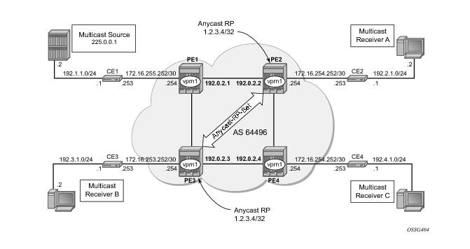
The network topology is displayed in Figure 92. The setup consists of 4 x 7750s acting as Provide Edge (PE) routers within a single Autonomous System (AS).
Figure 92: Network Topology for Anycast RP
Connected to each PE is a single 7750 acting as a Customer Edge (CE) router. CE-1 has a single multicast source connected, and PEs 2 to 4 each have a single receiver connected which will receive the multicast stream from the source. In this section, each receiver is IGMPv2 capable, and so will issue IGMPv2 reports. A Rendezvous Point is required by the C-signaling plane to resolve each (*,G) group state into an (S,G) state. In this case, two RPs are chosen to form an Anycast set to resolve each (*,G) group into an (S,G) state.
Multicast traffic from the source group 225.0.0.1 is streamed toward router CE-1. Receivers connected to PE-2, PE-3 and PE-4 are interested in joining this multicast group.
 
Anycast RP - PE VPRN Configuration
As each PE contains a CE which will be part of the multicast VRF, it is necessary to enable PIM on each interface containing an attachment circuit towards a CE, and to configure the I-PMSI multicast tunnel for the VRF.
As previously stated, there is a requirement for an RP, as Customer Multicast signaling will be PIM-ASM and IGMPv2.
In this case, an Anycast RP will be used. This is configured on PE-2 and PE-3, and an anycast set is created.
As each PE contains a CE which will be part of the multicast VRF, it is necessary to enable PIM on each interface containing an attachment circuit towards a CE, and to configure the I-PMSI multicast tunnel for the VRF.
The following output shows the VPRN configuration for PE-2 containing the RP and anycast RP configuration:
 
A:PE-2#configure service vprn 1
interface "rp" create
address 10.2.3.5/32
loopback
exit
interface "lo1" create
address 10.0.0.2/32
loopback
exit
pim
interface "int-pe2-ce2" #Attachment circuit towards CE
exit
interface "rp" #RP interface
exit
interface "lo1" #loopback interface for inter RP communication
exit
rp
static
address 10.2.3.5
group-prefix 225.0.0.0/8
exit
exit
anycast 10.2.3.5 #Anycast RP IP address
rp-set-peer 10.0.0.2 #IP address of THIS router
rp-set-peer 10.0.0.3 #IP address of peer router
exit
exit
exit
mvpn
provider-tunnel
inclusive
pim asm 239.255.255.1
exit
exit
exit
exit
no shutdown
 
Similarly, the VPRN configuration for PE-3 is:
A:PE-3#configure service vprn 1
interface "rp" create
address 10.2.3.5/32
loopback
exit
interface "lo1" create
address 10.0.0.3/32
loopback
exit
pim
interface "int-pe3-ce3" #Attachment circuit towards CE
exit
interface "rp" #RP interface
exit
interface "lo1" #loopback interface for inter RP communication
exit
rp
static
address 10.2.3.5
group-prefix 225.0.0.0/8
exit
exit
anycast 10.2.3.5 #Anycast RP IP address
rp-set-peer 10.0.0.2 #IP address of THIS router
rp-set-peer 10.0.0.3 #IP address of peer router
exit
exit
exit
mvpn
provider-tunnel
inclusive
pim asm 239.255.255.1
exit
exit
exit
exit
no shutdown
 
As previously stated, there is a requirement for an RP, as customer multicast signaling will be PIM-ASM and IGMPv2.
In this case, an anycast RP will be used. This is configured on PE-2 and PE-, and an anycast set is created.
The anycast address will be 10.2.3.5/32 and is created as an interface called rp on both PE-2 and PE-3.
An additional loopback interface, called lo1 is created on each VPRN on PEs containing the anycast address. These are used as source addresses for communication between the routers within the RP set. These addresses will be automatically advertised to all PEs as vpn-ipv4 addresses, and will be installed in the VRF 1 forwarding table of all PEs containing VPRN 1.
Note: All routers containing RP must have their own loopback address included in the RP set as well as all peer routers.
The multicast group address used for the Inclusive PMSI is chosen to be 239.255.255.1 and must be the same on all PEs for this VPRN instance. This is analogous to the MDT within the Draft-Rosen implementation.
Verify that PIM in the global routing table (GRT) has signalled the I-PMSIs.
For the PE acting as the RP for global PIM:
A:PE-1# show router pim group
===============================================================================
PIM Groups ipv4
===============================================================================
Group Address Type Spt Bit Inc Intf No.Oifs
Source Address RP
-------------------------------------------------------------------------------
239.255.255.1 (*,G) 3
* 192.0.2.1
239.255.255.1 (S,G) spt system 3
192.0.2.1 192.0.2.1
239.255.255.1 (S,G) spt int-pe1-pe2 2
192.0.2.2 192.0.2.1
239.255.255.1 (S,G) spt int-pe1-pe3 2
192.0.2.3 192.0.2.1
-------------------------------------------------------------------------------
Groups : 4
===============================================================================
A:PE-1#
 
All other PEs will have:
===============================================================================
PIM Groups ipv4
===============================================================================
Group Address                           Type     Spt Bit Inc Intf       No.Oifs
   Source Address                          RP                                  
-------------------------------------------------------------------------------
239.255.255.1                           (*,G)            int-pe2-pe1    1      
   *                                       192.0.2.1
239.255.255.1                           (S,G)    spt     system         2      
   192.0.2.2                               192.0.2.1
-------------------------------------------------------------------------------
Groups : 2
===============================================================================
 
This shows a (S,G) join towards the RP at 192.0.2.1, plus a (*,G) join from RP. These represent the outgoing and incoming PIM interfaces for the VRF.
This results in a series of PIM neighbors through the I-PMSIs within the VRF, which are maintained using PIM hellos.
A:PE-1# show router 1 pim neighbor
===============================================================================
PIM Neighbor ipv4
===============================================================================
Interface Nbr DR Prty Up Time Expiry Time Hold Time
Nbr Address
-------------------------------------------------------------------------------
int-pe1-ce1 1 1d 02:07:04 0d 00:01:35 105
172.16.255.253
1-mt-239.255.255.1 1 2d 00:37:32 0d 00:01:23 105
192.0.2.2
1-mt-239.255.255.1 1 2d 00:37:12 0d 00:01:31 105
192.0.2.3
-------------------------------------------------------------------------------
Neighbors : 3
===============================================================================
A:PE-1#
 
Verify PIM RP set:
*A:PE-2# show router 1 pim anycast
===============================================================================
PIM Anycast RP Entries ipv4
===============================================================================
Anycast RP Anycast RP Peer
-------------------------------------------------------------------------------
10.2.3.5 10.0.0.2
10.0.0.3
-------------------------------------------------------------------------------
PIM Anycast RP Entries : 2
===============================================================================
*A:PE-2#
 
Anycast RP — Customer Edge Router Multicast Configuration
Each CE router will have a PIM neighbor peer relationship with its nearest PE.
The CE router (CE-1) containing the source will have PIM enabled on the interface connected to the source.
A:CE-1# configure service vprn 1
autonomous-system 64497
route-distinguisher 64497:1
interface "int-ce1-pe1" create
address 172.16.255.253/30
sap 1/1/1:1 create
exit
exit
interface "to-source" create
address 192.168.1.1/24
sap 1/1/3:1 create
exit
exit
pim
interface "int-ce1-pe1"
exit
interface "to-source"
exit
rp
static
address 10.2.3.5
group-prefix 225.0.0.0/8
exit
exit
no shutdown
 
The CE containing the receivers will have IGMP enabled on the interface connected to the receivers.
A:CE-2# configure service vprn 1
autonomous-system 64498
route-distinguisher 64498:1
interface "to-104/2" create
address 192.168.2.1/24
sap 1/1/4:1 create
exit
exit
interface "int-ce2-pe2" create
address 172.16.254.253/30
sap 1/1/1:1 create
exit
exit
static-route 0.0.0.0/0 next-hop 172.16.254.254
igmp
interface "RX-A"
exit
exit
no shutdown
 
 
Traffic Flow
Figure 93: IGMP and PIM Control Messaging Schematic
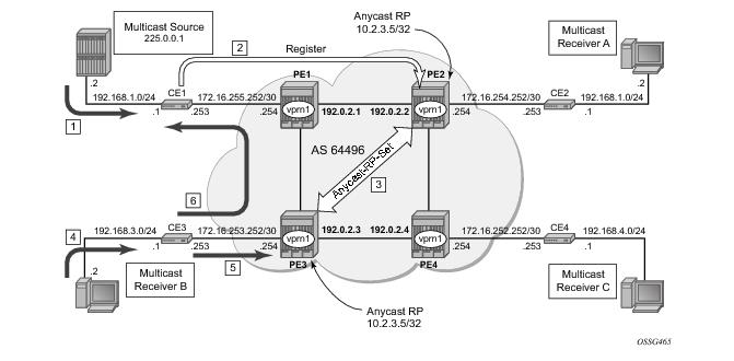
Figure 93 shows the sequence of IGMP and PIM control messaging.
1.
2.
 
A:CE-1# show router 1 pim group detail
===============================================================================
PIM Source Group ipv4
===============================================================================
Group Address : 225.0.0.1
Source Address : 192.168.1.2
RP Address : 10.2.3.5
Flags : Type : (S,G)
MRIB Next Hop : 192.168.1.2
MRIB Src Flags : direct Keepalive Timer Exp: 0d 00:03:19
Up Time : 0d 00:00:10 Resolved By : rtable-u
Up JP State : Not Joined Up JP Expiry : 0d 00:00:00
Up JP Rpt : Not Joined StarG Up JP Rpt Override : 0d 00:00:00
Register State : Pruned Register Stop Exp : 0d 00:00:38
Reg From Anycast RP: No
Rpf Neighbor : 192.168.1.2
Incoming Intf : to-source
Outgoing Intf List :
Curr Fwding Rate : 0.0 kbps
Forwarded Packets : 292 Discarded Packets : 0
Forwarded Octets : 12264 RPF Mismatches : 0
Spt threshold : 0 kbps ECMP opt threshold : 7
Admin bandwidth : 1 kbps
-------------------------------------------------------------------------------
Groups : 1
===============================================================================
A:CE-1#
 
The register message is sent to the nearest RP, the RP with the lowest IGP cost.
As the Register is sent through PE-1, it is PE-1 that determines which RP will receive the message.
A:PE-1# show router 1 route-table 10.2.3.5/32
===============================================================================
Route Table (Service: 1)
===============================================================================
Dest Prefix Type Proto Age Pref
Next Hop[Interface Name] Metric
-------------------------------------------------------------------------------
10.2.3.5/32 Remote BGP VPN 19h49m49s 170
192.0.2.2 0
-------------------------------------------------------------------------------
No. of Routes: 1
===============================================================================
A:PE-1#
 
The PE which will receive the register is 192.0.2.2 PE-2. The PIM group status on PE-2 is:
*A:PE-2# show router 1 pim group
===============================================================================
PIM Groups ipv4
===============================================================================
Group Address Type Spt Bit Inc Intf No.Oifs
Source Address RP
-------------------------------------------------------------------------------
225.0.0.1 (S,G) 1-mt-239.255.* 0
192.168.1.2 10.2.3.5
-------------------------------------------------------------------------------
Groups : 1
===============================================================================
*A:PE-2#
 
This shows that RP is aware of the (S,G) status of the group 225.1.1.1, and becomes a root of a shared tree for this group. Note that the Outgoing Interface List (OIL) is empty.
3.
The PIM status of the group 225.0.0.1 on PE-3 is:
A:PE-3# show router 1 pim group
===============================================================================
PIM Groups ipv4
===============================================================================
Group Address Type Spt Bit Inc Intf No.Oifs
Source Address RP
-------------------------------------------------------------------------------
225.0.0.1 (S,G) 1-mt-239.255.* 0
192.168.1.2 10.2.3.4
-------------------------------------------------------------------------------
Groups : 1
===============================================================================
* indicates that the corresponding row element may have been truncated.
A:PE-3#
 
Now both PEs within the RP set for VPRN have an (S,G) state for 225.0.0.1.
4.
5.
PE-3 already has (S,G) state for this group, so will forward traffic towards receiver B.
6.
The join is propagated across the provider network, towards PE-1 which is the resolved RPF next hop for the source.
A:CE-3# show router 1 pim group type sg detail
===============================================================================
PIM Source Group ipv4
===============================================================================
Group Address : 225.0.0.1
Source Address : 192.168.1.2
RP Address : 10.2.3.5
Flags : spt Type : (S,G)
MRIB Next Hop : 172.16.253.254
MRIB Src Flags : remote Keepalive Timer Exp: 0d 00:02:04
Up Time : 0d 00:01:28 Resolved By : rtable-u
Up JP State : Joined Up JP Expiry : 0d 00:00:32
Up JP Rpt : Not Pruned Up JP Rpt Override : 0d 00:00:00
 
Register State : No Info
Reg From Anycast RP: No
Rpf Neighbor : 172.16.253.254
Incoming Intf : int-ce3-pe3
Outgoing Intf List : RX-B
Curr Fwding Rate : 16.8 kbps
Forwarded Packets : 3920 Discarded Packets : 0
Forwarded Octets : 164640 RPF Mismatches : 0
Spt threshold : 0 kbps ECMP opt threshold : 7
Admin bandwidth : 1 kbps
-------------------------------------------------------------------------------
Groups : 1
===============================================================================
A:CE-3#
 
The join is received by CE-1, which contains the subnet of the source.
CE-1 now recognizes the multicast group as a valid stream. This becomes the root of the shortest path tree for the group.
A:CE-1# show router 1 pim group
===============================================================================
PIM Groups ipv4
===============================================================================
Group Address Type Spt Bit Inc Intf No.Oifs
Source Address RP
-------------------------------------------------------------------------------
225.0.0.1 (S,G) spt to-source 1
192.168.1.2
-------------------------------------------------------------------------------
Groups : 1
===============================================================================
A:CE-1#
 
 
PIM Source-Specific Multicasting
There is no requirement for an RP, as customer multicast signaling will be PIM-SSM. The Multicast group address used for the PMSI must be the same on all PEs for this VPRN instance.
Figure 94: PIM SSM in Customer Signaling Plane
The following output shows the VPRN configuration for PIM and MVPN for PE-1.
 
A:PE-1#configure service vprn 1
pim
interface "int-pe1-ce1"
exit
mvpn
provider-tunnel
inclusive
pim asm 239.255.255.1
exit
exit
exit
exit
no shutdown


There is a similar configuration required for each of the other PEs. Verify that PIM in the Global routing table (GRT) has signalled the I-PMSIs.
For the PE acting as the RP for global PIM:
A:PE-1# show router pim group
===============================================================================
PIM Groups ipv4
===============================================================================
Group Address Type Spt Bit Inc Intf No.Oifs
Source Address RP
-------------------------------------------------------------------------------
239.255.255.1 (*,G) 3
* 192.0.2.1
239.255.255.1 (S,G) spt system 3
192.0.2.1 192.0.2.1
239.255.255.1 (S,G) spt int-pe1-pe2 2
192.0.2.2 192.0.2.1
239.255.255.1 (S,G) spt int-pe1-pe3 2
192.0.2.3 192.0.2.1
-------------------------------------------------------------------------------
Groups : 4
===============================================================================
A:PE-1#
 
All other PEs will have:
A:PE-2# show router pim group
===============================================================================
PIM Groups ipv4
===============================================================================
Group Address Type Spt Bit Inc Intf No.Oifs
Source Address RP
-------------------------------------------------------------------------------
239.255.255.1 (*,G) int-pe2-pe1 1
* 192.0.2.1
239.255.255.1 (S,G) spt system 2
192.0.2.2 192.0.2.1
-------------------------------------------------------------------------------
Groups : 2
===============================================================================
A:PE-2#
 
This shows a (S,G) join towards the RP at 192.0.2.1, plus a (*,G) join from RP. These represent the outgoing and incoming PIM interfaces for the VRF.
This results in a series of PIM neighbors through the I-PMSIs within the VRF, which are maintained using PIM hellos.
A:PE-1# show router 1 pim neighbor
===============================================================================
PIM Neighbor ipv4
===============================================================================
Interface Nbr DR Prty Up Time Expiry Time Hold Time
Nbr Address
-------------------------------------------------------------------------------
int-pe1-ce1 1 1d 02:07:04 0d 00:01:35 105
172.16.255.253
1-mt-239.255.255.1 1 2d 00:37:32 0d 00:01:23 105
192.0.2.2
1-mt-239.255.255.1 1 2d 00:37:12 0d 00:01:31 105
192.0.2.3
-------------------------------------------------------------------------------
Neighbors : 3
===============================================================================
A:PE-1#
 
PIM SSM — Customer Edge Router Multicast Configuration
Each CE router will have a PIM neighbor peer relationship with its nearest PE.
The CE router (CE-1) containing the source will have PIM enabled on the interface connected to the source.
 
A:CE-1# configure service vprn 1
autonomous-system 64497
route-distinguisher 64497:1
interface "int-ce1-pe1" create
address 172.16.255.253/30
sap 1/1/1:1 create
exit
exit
interface "to-source" create
address 192.168.1.1/24
sap 1/1/3:1 create
exit
exit
pim
interface "int-ce1-pe1"
exit
interface "to-source"
exit
no shutdown
 
The CE containing the receivers will have IGMP enabled on the interface connected to the receivers and PIM on the interface facing the PE.
A:CE-2# configure service vprn 1
autonomous-system 64498
route-distinguisher 64498:1
interface "RX-A" create
address 192.2.1.1/24
sap 1/1/4:1 create
exit
exit
interface "int-ce2-pe2" create
address 172.16.254.253/30
sap 1/1/1:1 create
exit
exit
static-route 192.168.1.0/24 next-hop 172.16.254.254
igmp
interface "RX-A"
exit
exit
pim
interface "int-ce2-pe2"
exit
no shutdown
 
 
Traffic Flow
The source multicasts a stream towards CE-1. As there is no receiver interested in the group at this time, there are no outgoing interfaces, so the Outgoing Interface List (OIL) is empty.
A:CE-1# show router 1 pim group
===============================================================================
PIM Groups ipv4
===============================================================================
Group Address Type Spt Bit Inc Intf No.Oifs
Source Address RP
-------------------------------------------------------------------------------
232.0.0.1 (S,G) to-104/1 0
192.168.1.2
-------------------------------------------------------------------------------
Groups : 1 ================================================================================
A:CE-1#
 
The receiver A, wishes to join the group 232.0.0.1, and so sends in an IGMPv3 report towards CE-2. CE-2 recognizes the report, which contains the source 192.168.1.2 in the INCLUDE filter list.
A:CE-2# show router 1 igmp group
===============================================================================
IGMP Groups
===============================================================================
(192.168.1.2,232.0.0.1) Up Time : 0d 00:00:33
Fwd List : to-104/2
-------------------------------------------------------------------------------
(*,G)/(S,G) Entries : 1
===============================================================================
A:CE-2#
 
CE-2 does a RPF lookup of the source address in the route table, and issues a PIM join towards the source.
The join is propagated across the provider network, towards PE-1 which is the resolved RPF next hop for the source.
A:PE-1# show router 1 pim group detail
===============================================================================
PIM Source Group ipv4
===============================================================================
Group Address : 232.0.0.1
Source Address : 192.168.1.2
RP Address : 172.16.254.254
Flags : spt Type : (S,G)
MRIB Next Hop : 172.16.255.253
MRIB Src Flags : remote Keepalive Timer Exp: 0d 00:01:43
Up Time : 0d 00:08:47 Resolved By : rtable-u
Up JP State : Joined Up JP Expiry : 0d 00:00:13
Up JP Rpt : Not Joined StarG Up JP Rpt Override : 0d 00:00:00
Register State : No Info
Reg From Anycast RP: No
Rpf Neighbor : 172.16.255.253
Incoming Intf : int-pe1-ce1
Outgoing Intf List : 1-mt-239.255.255.1
Curr Fwding Rate : 33.6 kbps
Forwarded Packets : 52214 Discarded Packets : 0
Forwarded Octets : 2192988 RPF Mismatches : 0
Spt threshold : 0 kbps ECMP opt threshold : 7
Admin bandwidth : 1 kbps
-------------------------------------------------------------------------------
Groups : 1
 
Note that the outgoing interface is the I-PMSI.
The join is received by CE-1, which contains the subnet of the source.
CE-1 now recognizes the multicast group as a valid stream. This becomes the root of the shortest path tree for the group.
A:CE-1# show router 1 pim group
===============================================================================
PIM Groups ipv4
===============================================================================
Group Address Type Spt Bit Inc Intf No.Oifs
Source Address RP
-------------------------------------------------------------------------------
232.0.0.1 (S,G) spt to-source 1
192.168.1.2
-------------------------------------------------------------------------------
Groups : 1
===============================================================================
A:CE-1#
 
PE BGP Auto-Discovery
Discovery of multicast-enabled Virtual Private Networks (MVPNs) can also be achieved using BGP. To this end, any PE that is a member of a Multicast VPN will advertise this using a BGP Multi-protocol Reachable Next-Hop Router Layer Information (NRLI) update that is sent to all PEs within the AS. This update will contain an Intra-AS I-PMSI auto-discovery Route type, also known as an Intra-AD. These use an address family, mvpn-ipv4, so each PE must be configured to originate and accept such updates.
This is achieved in the global routing table within the BGP context.
A:PE-1#configure router bgp
group "internal"
family vpn-ipv4 mvpn-ipv4
peer-as 64496
neighbor 192.0.2.2
exit
neighbor 192.0.2.3
exit
neighbor 192.0.2.4
exit
exit
 
This allows each BGP speaker to advertise its capabilities within a BGP Open message.
When the peers become established, the address family capabilities should look like the following:
A:PE-1# show router bgp summary
===============================================================================
BGP Router ID:192.0.2.1 AS:64496 Local AS:64496
===============================================================================
BGP Admin State : Up BGP Oper State : Up
Total Peer Groups : 1 Total Peers : 3
Total BGP Paths : 15 Total Path Memory : 1932
Total IPv4 Remote Rts : 0 Total IPv4 Rem. Active Rts : 0
Total IPv6 Remote Rts : 0 Total IPv6 Rem. Active Rts : 0
Total Supressed Rts : 0 Total Hist. Rts : 0
Total Decay Rts : 0
Total VPN Peer Groups : 1 Total VPN Peers : 1
Total VPN Local Rts : 2
Total VPN-IPv4 Rem. Rts : 7 Total VPN-IPv4 Rem. Act. Rts: 6
Total VPN-IPv6 Rem. Rts : 0 Total VPN-IPv6 Rem. Act. Rts: 0
Total L2-VPN Rem. Rts : 0 Total L2VPN Rem. Act. Rts : 0
Total VPN Supp. Rts : 0 Total VPN Hist. Rts : 0
Total VPN Decay Rts : 0
Total MVPN-IPv4 Rem Rts : 3 Total MVPN-IPv4 Rem Act Rts : 3
===============================================================================
BGP Summary
===============================================================================
Neighbor
AS PktRcvd InQ Up/Down State|Rcv/Act/Sent (Addr Family)
PktSent OutQ
-------------------------------------------------------------------------------
192.0.2.2
64496 26629 0 07d01h59m 3/3/1 (VpnIPv4)
26737 0 1/1/1 (MvpnIpv4)
192.0.2.3
64496 26647 0 07d01h59m 3/2/1 (VpnIPv4)
26728 0 1/1/1 (MvpnIpv4)
192.0.2.4
64496 26632 0 07d01h59m 1/1/1 (VpnIPv4)
26685 0 1/1/1 (MvpnIpv4)
===============================================================================
A:PE-1#
 
BGP Auto-Discovery — PE VPRN Multicast Configuration
As each PE contains a CE which will be part of the multicast VRF, it is necessary to enable PIM on each interface containing an attachment circuit towards a CE, and to configure the I-PMSI multicast tunnel for the VRF.
In order for the BGP routes to be accepted into the VRF, a route-target community is required (vrf-target). This is configured in the configure service vprn 1 mvpn context and, in this case, is set to the same value as the unicast vrf-target, the vrf-target community as the configure service vprn 1 vrf-target context.
On each PE, A VPRN instance is configured as follows
A:PE-2# configure service vprn 1
autonomous-system 64496
route-distinguisher 64496:1
auto-bind ldp
vrf-target target:64496:1
interface "int-pe2-ce2" create
address 172.16.254.254/30
sap 1/1/3:1 create
exit
exit
pim
interface "int-pe2-ce2"
exit
mvpn
auto-discovery
provider-tunnel
inclusive
pim asm 239.255.255.1
exit
exit
exit
vrf-target unicast
exit
exit
no shutdown
The multicast group address used for the PMSI must be the same on all PEs for this VPRN instance.
The presence of auto-discovery will initiate BGP updates between the PEs that contain an MVPN, such as Intra-AD MVPN routes, are generated and advertised to each peer
A:PE-1# show router bgp routes mvpn-ipv4
===============================================================================
BGP Router ID:192.0.2.1 AS:64496 Local AS:64496
===============================================================================
Legend -
Status codes : u - used, s - suppressed, h - history, d - decayed, * - valid
Origin codes : i - IGP, e - EGP, ? - incomplete, > - best
 
===============================================================================
BGP MVPN-IPv4 Routes
===============================================================================
Flag RouteType OriginatorIP LocalPref MED
RD SourceAS VPNLabel
Nexthop SourceIP
As-Path GroupIP
-------------------------------------------------------------------------------
u*>i Intra-Ad 192.0.2.2 100 0
64496:1 - -
192.0.2.2 -
No As-Path -
u*>i Intra-Ad 192.0.2.3 100 0
64496:1 - -
192.0.2.3 -
No As-Path -
u*>i Intra-Ad 192.0.2.4 100 0
64496:1 - -
192.0.2.4 -
No As-Path -
-------------------------------------------------------------------------------
Routes : 3
===============================================================================
*A:PE-1#
 
This shows that PE-1 has received an Intra-AD route from each of the other PEs, each of which has multicast VPRN 1 configured.
Examining one of the Intra-AD routes from PE-2 shows that the route-target community matches the unicast VRF-target (64496:1), and also that the PMSI tree has a multicast group address of 239.255.255.1, which matches the I-PMSI group configuration on PE-1.
 
A:PE-1# show router bgp routes mvpn-ipv4 type intra-ad originator-ip 192.0.2.2 detail
===============================================================================
BGP Router ID:192.0.2.1 AS:64496 Local AS:64496
===============================================================================
Legend -
Status codes : u - used, s - suppressed, h - history, d - decayed, * - valid
Origin codes : i - IGP, e - EGP, ? - incomplete, > - best
===============================================================================
BGP MVPN-IPv4 Routes
===============================================================================
Route Type : Intra-Ad
Route Dist. : 64496:1
Originator IP : 192.0.2.2
Nexthop : 192.0.2.2
From : 192.0.2.2
Res. Nexthop : 0.0.0.0
Local Pref. : 100 Interface Name : NotAvailable
Aggregator AS : None Aggregator : None
Atomic Aggr. : Not Atomic MED : 0
Community : target:64496:1
Cluster : No Cluster Members
Originator Id : None Peer Router Id : 192.0.2.2
Flags : Used Valid Best IGP
AS-Path : No As-Path
-------------------------------------------------------------------------------
PMSI Tunnel Attribute :
Tunnel-type : PIM-SM Tree Flags : Local Info not Required
MPLS Label : 0x0
Sender : 192.0.2.2 P-Group : 239.255.255.1
-------------------------------------------------------------------------------
-------------------------------------------------------------------------------
Routes : 1
===============================================================================
A:PE-1#
 
Verify that PIM in the global routing table (GRT) has signalled the I-PMSIs.
For the PE acting as the RP for global PIM:
A:PE-1# show router pim group
===============================================================================
PIM Groups ipv4
===============================================================================
Group Address Type Spt Bit Inc Intf No.Oifs
Source Address RP
-------------------------------------------------------------------------------
239.255.255.1 (*,G) 3
* 192.0.2.1
239.255.255.1 (S,G) spt system 3
192.0.2.1 192.0.2.1
239.255.255.1 (S,G) spt int-pe1-pe2 2
192.0.2.2 192.0.2.1
239.255.255.1 (S,G) spt int-pe1-pe3 2
192.0.2.3 192.0.2.1
-------------------------------------------------------------------------------
Groups : 4
===============================================================================
A:PE-1#
 
This shows an incoming (S,G) join from all other PEs within the multicast VRF, plus an outgoing (*,G) join to the same PEs.
All other PEs will have the following PIM groups
A:PE-2# show router pim group
===============================================================================
PIM Groups ipv4
===============================================================================
Group Address Type Spt Bit Inc Intf No.Oifs
Source Address RP
-------------------------------------------------------------------------------
239.255.255.1 (*,G) int-pe2-pe1 1
* 192.0.2.1
239.255.255.1 (S,G) spt system 2
192.0.2.2 192.0.2.1
-------------------------------------------------------------------------------
Groups : 2
===============================================================================
A:PE-2#
This shows a (S,G) join towards the RP at 192.0.2.1, plus a (*,G) join from RP. These represent the outgoing and incoming PIM interfaces for the VRF.
This results in a series of PIM neighbors through the I-PMSIs within the VRF. As the neighbors were discovered using BGP (rather than with PIM as per Draft-Rosen), there are no PIM hellos exchanged.
A:PE-1# show router 1 pim neighbor
===============================================================================
PIM Neighbor ipv4
===============================================================================
Interface Nbr DR Prty Up Time Expiry Time Hold Time
Nbr Address
-------------------------------------------------------------------------------
int-pe1-ce1 1 1d 01:18:59 0d 00:01:24 105
172.16.255.253
1-mt-239.255.255.1 1 1d 01:18:22 never 65535
192.0.2.2
1-mt-239.255.255.1 1 1d 01:18:59 never 65535
192.0.2.3
1-mt-239.255.255.1 1 1d 01:18:59 never 65535
192.0.2.4
-------------------------------------------------------------------------------
Neighbors : 4
===============================================================================
*A:PE-1#
 
BGP Auto-Discovery — Customer Signaling Domain
As the customer signaling is independent from the provider PE discovery mechanism, all of the customer signaling techniques described when using PIM for auto-discovery within provider domain are also applicable when using BGP for auto-discovery, namely
 
Data Path Using Selective PMSI
When a configurable data threshold for a multicast group has been exceeded, multicast traffic across the Provider network can be switched to a selective PMSI (S-PMSI).
This has to be configured as a separate group and must contain a threshold which, if exceeded, will see a new PMSI signalled by the PE nearest the source, and traffic switched onto the S-PMSI.
 
*A:PE-1# configure service vprn 1
mvpn
provider-tunnel
inclusive
pim asm 239.255.255.1
exit
exit
selective
data-threshold 232.0.0.0/8 1
pim-ssm 232.255.1.0/24
exit
exit
exit
no shutdown
 
This shows that when the traffic threshold for multicast groups covered by the range 232.0.0.0/8 exceeds 1kbps between a pair of PEs, then an S-PMSI is signalled between the PEs. This is a separate multicast tunnel over which traffic in the given group now flows.
 
*A:PE-1# show router 1 pim s-pmsi detail
===============================================================================
PIM Selective provider tunnels
===============================================================================
Md Source Address : 192.0.2.1 Md Group Address : 232.255.1.14
Number of VPN SGs : 1 Uptime : 0d 00:00:12
MT IfIndex : 16395
 
VPN Group Address : 232.0.0.1 VPN Source Address : 192.168.1.2
State : TX Joined Mdt Threshold : 1
Join Timer : 0d 00:00:47 Holddown Timer : 0d 00:00:47
===============================================================================
PIM Selective provider tunnels Interfaces : 1
===============================================================================
*A:PE-1#
 
In this example, the (S,G) group is (192.168.1.2, 225.0.0.1). As the data rate has exceeded the configured MDT threshold of 1kbps, a new provider tunnel with a group address of 232.255.1.14 has been signalled and now carries the multicast stream.
 
The TX Joined state indicates that the S-PMSI has been sourced at this PE — PE-1.
Comparing this to PE-3, where a receiver is connected through a CE indicates that it has received a join to connect the S-PMSI.
 
*A:PE-3# show router 1 pim s-pmsi detail
===============================================================================
PIM Selective provider tunnels
===============================================================================
Md Source Address : 192.0.2.1 Md Group Address : 232.255.1.14
Number of VPN SGs : 1 Uptime : 0d 00:05:13
MT IfIndex : 24576 Egress Fwding Rate : 52.8 kbps
 
VPN Group Address : 232.0.0.1 VPN Source Address : 192.168.1.2
State : RX Joined
Expiry Timer : 0d 00:02:31
===============================================================================
PIM Selective provider tunnels Interfaces : 1
...
===============================================================================
*A:PE-3#
 
 
Conclusion
This note provides configuration on how to configure multicast within a VPRN with next generation multicast VPN techniques. Specifically, discovery of multicast VPNs using PIM and BGP auto-discovery mechanisms are describer with a number of ASM and SSM signaling techniques within the customer domain.