For feedback and comments:
documentation.feedback@alcatel-lucent.com
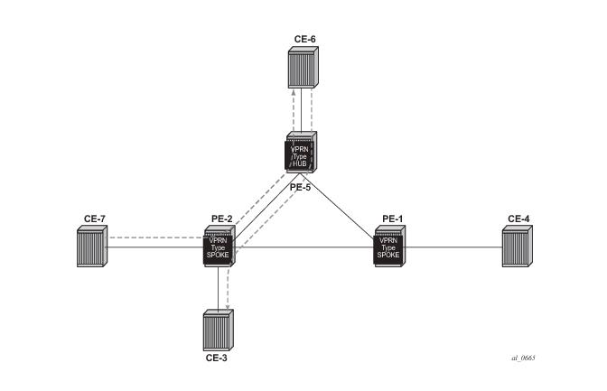
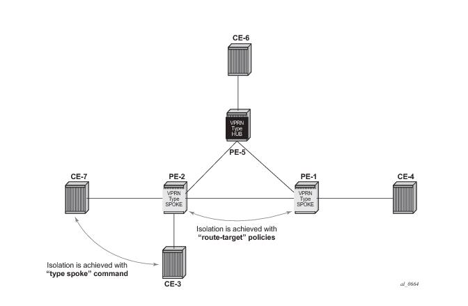
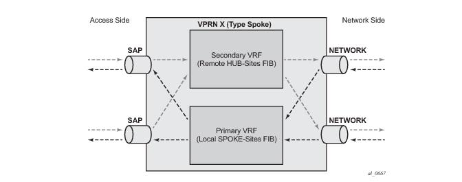
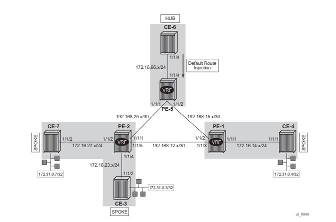
Table of Contents Previous Next Index PDF


Layer 3 VPN: VPRN Type Spoke
In This Chapter
This section provides information about Layer 3 VPRN CE hub and spoke architecture.
Topics in this section include:
Applicability
This example is applicable to the 7950 XRS, 7750 SR and 7450 ESS in mixed mode with a CPM3 or later, and is limited to IOM3-XP line cards or later. It is also supported on 7750 SR c4/12 systems. The configuration was tested on release 12.0.R3.
 
Summary
This example provides a basic technology overview and configuration examples of a network topology used for a Layer 3 VPRN CE hub and spoke architecture.
Knowledge of the Alcatel-Lucent’s Layer 3 VPN concepts is assumed throughout this document.
 
Overview
Prior to SR OS release 12.0 a CE hub and spoke architecture was partially supported. Internal optimization was available for the hub sites connected to the same PE router only. This feature is known as VPRN type hub. If, on the other hand, multiple spoke sites were connected to the same PE router, separate VPRN instances had to be created to maintain the split horizon forwarding behavior. This approach was complex, hard to maintain and consumed extra VPRN instances.
Release 12.0.R1 adds new functionality to overcome these limitations. Introducing the VPRN type spoke feature allows multiple spoke sites to be kept within the same VPRN instance while at the same time maintaining the split horizon approach such that spoke sites cannot send traffic directly to each other.
The primary goal of the feature is to allow multiple spoke sites to be part of a single VPRN instance without allowing direct communication between the spoke CE sites which are part of that VPRN (of type spoke). The packet flow is demonstrated in Figure 87.
Figure 87: CE Hub and Spoke Data Path
The only way for CE-7 to communicate with CE-3 is via hub site CE-6. The same applies to CE-7 and CE-4 communication. The VPRN on PE-2 is configured as type spoke and has IP interfaces using SAPs or spoke SDPs that are considered spoke sites only. No direct communication between any of the spoke CE sites in the network is allowed.
This is achieved using two techniques (Figure 88).
Use the type spoke command under the VPRN context as explained later.
Figure 88: CE Hub and Spoke Control Plane Isolation
When a VPRN on a PE router is configured as type spoke then the internal forwarding logic changes as demonstrated in Figure 89.
Figure 89: Internal VPRN Logic on a PE Router
 
Configuration
The physical topology and addressing scheme are presented in Figure 90.
Figure 90: CE Hub and Spoke Topology and Addressing Scheme
The configuration of PE-2 and PE-5 are the main focus of this example. The configuration of PE-1 is similar to that of PE-2.
 
Hub Site Configuration
Only the essential part of the configuration is provided for the hub site.
PE-5 is configured with VPRN 1 providing OSPF connectivity to customer CE-6.
A:PE-5# configure service vprn 1 
*A:PE-5>config>service>vprn# info 
----------------------------------------------
            vrf-import "vrf-import"
            vrf-export "vrf-export"
            route-distinguisher 1:5
            type hub
            auto-bind mpls-gre
            interface "int-PE-5-CE-6" create
                address 172.16.56.1/24
                sap 1/1/3:100 create
                exit
            exit
            ospf
                export "export-ospf"
                area 0.0.0.0
                    interface "int-PE-5-CE-6"
                        interface-type point-to-point
                        mtu 1500
                        no shutdown
                    exit
                exit
            exit
            no shutdown
 
Vrf-import and export policies are used to manipulate the vrf-target in order to achieve logical isolation between the spoke sites in the network.
*A:PE-5>config>router>policy-options# info 
----------------------------------------------
            community "hub-ext-comm" members "target:64500:11"
            community "spoke-ext-comm" members "target:64500:12"
            policy-statement "vrf-export"
                default-action accept
                    community add "hub-ext-comm"
                exit
            exit
            policy-statement "vrf-import"
                entry 10
                    from
                        community "spoke-ext-comm"
                    exit
                    action accept
                    exit
                exit
                default-action reject
            exit
 
At the same time CE-6 is configured (not shown) to advertise a default route which is used by all remote spoke CE sites to forward traffic via CE-6.
 
Hub Site Verification
The routing table (RIB) for VPRN 1 on PE-5 (hub site) lists all reachable networks.
*A:PE-5# show router 1 route-table 
===============================================================================
Route Table (Service: 1)
===============================================================================
Dest Prefix[Flags]                            Type    Proto     Age        Pref
      Next Hop[Interface Name]                                    Metric   
-------------------------------------------------------------------------------
0.0.0.0/0                                     Remote  OSPF      21h28m50s  150
       172.16.56.2                                                  1
172.16.14.0/24                                Remote  BGP VPN   00h15m59s  170
       192.0.2.1 (tunneled)                                         0
172.16.23.0/24                                Remote  BGP VPN   00h15m59s  170
       192.0.2.2 (tunneled)                                         0
172.16.27.0/24                                Remote  BGP VPN   00h15m59s  170
       192.0.2.2 (tunneled)                                         0
172.16.56.0/24                                Local   Local     21h29m07s  0
       int-PE-5-CE-6                                                0
172.31.0.3/32                                 Remote  BGP VPN   00h15m59s  170
       192.0.2.2 (tunneled)                                         0
172.31.0.4/32                                 Remote  BGP VPN   00h15m59s  170
       192.0.2.1 (tunneled)                                         0
172.31.0.7/32                                 Remote  BGP VPN   00h15m59s  170
       192.0.2.2 (tunneled)                                         0
-------------------------------------------------------------------------------
No. of Routes: 8
 
The forwarding table (FIB) for the primary VRF of VPRN 1 is displayed using following command. All remote spoke and hub sites are reachable via this VRF.
*A:PE-5# show router 1 fib 1 
===============================================================================
FIB Display
===============================================================================
Prefix                                                      Protocol
    NextHop                                                 
-------------------------------------------------------------------------------
0.0.0.0/0                                                   OSPF
    172.16.56.2 (int-PE-5-CE-6) 
172.16.14.0/24                                              BGP_VPN
    192.0.2.1 (VPRN Label:262143 Transport:LDP)
172.16.23.0/24                                              BGP_VPN
    192.0.2.2 (VPRN Label:262142 Transport:LDP)
172.16.27.0/24                                              BGP_VPN
    192.0.2.2 (VPRN Label:262142 Transport:LDP)
172.16.56.0/24                                              LOCAL
    172.16.56.0 (int-PE-5-CE-6) 
172.31.0.3/32                                               BGP_VPN
    192.0.2.2 (VPRN Label:262142 Transport:LDP)
172.31.0.4/32                                               BGP_VPN
    192.0.2.1 (VPRN Label:262143 Transport:LDP)
172.31.0.7/32                                               BGP_VPN
    192.0.2.2 (VPRN Label:262142 Transport:LDP)
-------------------------------------------------------------------------------
Total Entries : 8
-------------------------------------------------------------------------------
===============================================================================
 
The forwarding table for the secondary VRF of VPRN 1 is displayed using following command, including the secondary keyword. All local hub CE sites are reachable via this VRF.
*A:PE-5# show router 1 fib 1 secondary 
===============================================================================
FIB Display
===============================================================================
Prefix                                                      Protocol
    NextHop                                                 
-------------------------------------------------------------------------------
0.0.0.0/0                                                   OSPF
    172.16.56.2 (int-PE-5-CE-6) 
172.16.56.0/24                                              LOCAL
    172.16.56.0 (int-PE-5-CE-6) 
-------------------------------------------------------------------------------
Total Entries : 2
-------------------------------------------------------------------------------
===============================================================================
 
Spoke Site Configuration
According to the network topology two spoke VPRNs are present. One VPRN with two CE spoke sites connected is located on PE-2 and another VPRN with one spoke CE site is located on PE-1. The service configuration for PE-2 is shown below with the one for PE-1 being similar.
PE-2 is configured with VPRN 1, which has OSPF connectivity to the customer CE-3 and CE-7. Note the new command type spoke which is used to prevent direct CE spoke to CE spoke communications for this VPRN.
A:PE-2# configure service vprn 1 
A:PE-2>config>service>vprn# info 
----------------------------------------------
            vrf-import "vrf-import"
            vrf-export "vrf-export"
            route-distinguisher 1:2
            type spoke
            auto-bind mpls-gre
            interface "int-PE-2-CE-7" create
                address 172.16.27.1/24
                sap 1/1/2:100 create
                exit
            exit
            interface "int-PE-2-CE-3" create
                address 172.16.23.1/24
                sap 1/1/4:100 create
                exit
            exit
            ospf
                export "export-ospf"
                area 0.0.0.0
                    interface "int-PE-2-CE-7"
                        interface-type point-to-point
                        mtu 1500
                        no shutdown
                    exit
                    interface "int-PE-2-CE-3"
                        interface-type point-to-point
                        mtu 1500
                        no shutdown
                    exit
                exit
            exit
            no shutdown   
 
Vrf-import and export policies are used to build a hub-and-spoke topology in order to achieve a logical isolation between spoke sites connected to different PE routers.
*A:PE-2# configure router policy-options 
*A:PE-2>config>router>policy-options# info 
----------------------------------------------
            community "hub-ext-comm" members "target:64500:11"
            community "spoke-ext-comm" members "target:64500:12"
            policy-statement "vrf-export"
                default-action accept
                    community add "spoke-ext-comm"
                exit
            exit
            policy-statement "vrf-import"
                entry 10
                    from
                        community "hub-ext-comm"
                    exit
                    action accept
                    exit
                exit
                default-action reject
            exit
 
For connectivity verification purposes CE-3, CE-4 and CE-7 are configured to advertise their internal loopback interfaces via OSPF:
 
Spoke Site Verification
The RIB for VPRN 1 on PE-2 (spoke VPRN) lists all reachable networks.
The other spoke sites connected to the remote PEs (only CE-4 here, for example: 172.31.0.4/32)) are not present in the routing table.
PE-2’s local interface addresses (172.16.23.1/32 and 172.16.27.1/32) are present in the routing table of VPRN 1. From a FIB point of view these are reachable from any spoke VPRN but the spoke CE’s router host addresses are not. This fact does not influence the data plane isolation for the customer networks.
*A:PE-2# show router 1 route-table 
===============================================================================
Route Table (Service: 1)
===============================================================================
Dest Prefix[Flags]                            Type    Proto     Age        Pref
      Next Hop[Interface Name]                                    Metric   
-------------------------------------------------------------------------------
0.0.0.0/0                                     Remote  BGP VPN   00h19m04s  170
       192.0.2.5 (tunneled)                                         0
172.16.23.0/24                                Local   Local     21h55m36s  0
       int-PE-2-CE-3                                                0
172.16.23.1/32                                Remote  Host      21h55m36s  0
       int-PE-2-CE-3                                                0
172.16.27.0/24                                Local   Local     21h55m36s  0
       int-PE-2-CE-7                                                0
172.16.27.1/32                                Remote  Host      21h55m36s  0
       int-PE-2-CE-7                                                0
172.16.56.0/24                                Remote  BGP VPN   00h19m04s  170
       192.0.2.5 (tunneled)                                         0
172.31.0.3/32                                 Remote  OSPF      04h46m36s  10
       172.16.23.2                                                  100
172.31.0.7/32                                 Remote  OSPF      21h55m21s  10
       172.16.27.2                                                  100
-------------------------------------------------------------------------------
No. of Routes: 8
 
The FIB for the primary VRF of VPRN 1 shows all local spoke sites are reachable via this VRF.
*A:PE-2# show router 1 fib 1 
===============================================================================
FIB Display
===============================================================================
Prefix                                                      Protocol
    NextHop                                                 
-------------------------------------------------------------------------------
172.16.23.0/24                                              LOCAL
    172.16.23.0 (int-PE-2-CE-3) 
172.16.23.1/32                                              HOST
    Blackhole                                               
172.16.27.0/24                                              LOCAL
    172.16.27.0 (int-PE-2-CE-7) 
172.16.27.1/32                                              HOST
    Blackhole                                               
172.31.0.3/32                                               OSPF
    172.16.23.2 (int-PE-2-CE-3) 
172.31.0.7/32                                               OSPF
    172.16.27.2 (int-PE-2-CE-7) 
-------------------------------------------------------------------------------
Total Entries : 6 
-------------------------------------------------------------------------------
===============================================================================
 
The FIB for the secondary VRF of VPRN 1 shows the remote hub site (address 172.16.56.0/24) is reachable via this VRF.
*A:PE-2# show router 1 fib 1 secondary 
===============================================================================
FIB Display
===============================================================================
Prefix                                                      Protocol
    NextHop                                                 
-------------------------------------------------------------------------------
0.0.0.0/0                                                   BGP_VPN
    192.0.2.5 (VPRN Label:262141 Transport:LDP)
172.16.23.1/32                                              HOST
    Blackhole                                               
172.16.27.1/32                                              HOST
    Blackhole                                               
172.16.56.0/24                                              BGP_VPN
    192.0.2.5 (VPRN Label:262141 Transport:LDP)
-------------------------------------------------------------------------------
Total Entries : 4 
-------------------------------------------------------------------------------
===============================================================================
 
 
Spoke Sites Connectivity Verification
Without the VPRN spoke type configuration in VPRN 1 on PE-2 CE-3 takes the shortest path to CE-7, which violates the “hub and spoke” design approach explained above.
A:CE-3# traceroute 172.31.0.7 no-dns    
traceroute to 172.31.0.7, 30 hops max, 40 byte packets
  1  172.16.23.1    3.22 ms  14.3 ms  2.75 ms
  2  172.31.0.7    3.47 ms  3.34 ms  3.42 ms
A:CE-3# traceroute router 100 172.31.0.7 no-dns 
 
After enabling the type spoke feature, CE-3 takes the longest path via hub CE-6 to reach CE-7, as it should.
*A:CE-3# traceroute 172.31.0.7 no-dns 
traceroute to 172.31.0.7, 30 hops max, 40 byte packets
  1  172.16.23.1    3.16 ms  2.79 ms  2.79 ms
  2  0.0.0.0  * * * 
  3  172.16.56.2    69.7 ms  7.31 ms  10.5 ms
  4  172.16.56.1    32.0 ms  67.5 ms  80.6 ms
  5  172.16.27.1    7.54 ms  7.52 ms  33.6 ms
  6  172.31.0.7    77.4 ms  90.7 ms  12.8 ms
 
Similarly, the long path is taken by CE-3 to reach CE-4.
*A:CE-3# traceroute 172.31.0.4 no-dns 
traceroute to 172.31.0.4, 30 hops max, 40 byte packets
  1  172.16.23.1    72.6 ms  2.82 ms  2.72 ms
  2  0.0.0.0  * * * 
  3  172.16.56.2    10.8 ms  41.7 ms  9.51 ms
  4  172.16.56.1    10.6 ms  20.7 ms  10.8 ms
  5  172.16.14.1    11.8 ms  11.9 ms  11.6 ms
  6  172.31.0.4    20.9 ms  15.6 ms  15.4 ms
Conclusion
The VPRN type spoke feature completes the CE hub and spoke solution. It brings a new level of simplicity, scalability and flexibility to operators using this VPRN architecture for their customers.