Ethernet over SDH
Introduction
To connect remote PC LAN network sites via an SDH network without the need for intermediate bridges or routers, the 1643 AM or 1643 AMS network element is equipped with the Ethernet Interface extension card.
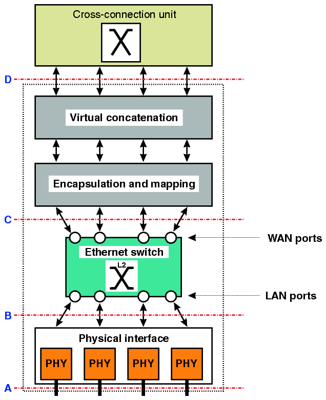
The following figure visualizes the basic design of a TransLAN® card:

Legend:
|
A |
The external interfaces, to which the end-customer's Ethernet LANs are physically connected. |
|
B |
The interface between the Ethernet physical interface port and the Ethernet switch. The internal interfaces of the Ethernet switch towards the Ethernet physical interface port are referred to as “LAN ports”. Note that two types of LAN ports can be differentiated according to their port role: “customer LAN ports” and “network LAN ports” (cf. Port provisioning). |
|
C |
The internal interface between the Ethernet switch and the encapsulation and mapping function. The internal interfaces of the Ethernet switch towards the encapsulation and mapping function are referred to as “WAN ports”. Note that two types of WAN ports can be differentiated according to their port role: “network WAN ports” and “customer WAN ports” (cf. Port provisioning). |
|
D |
The interface between the encapsulation and mapping function and the cross-connect function of the network element. This is were the virtually concatenated payload is cross-connected to be transported over the SDH network. |
The TransLAN® implementations use standardized protocols to transport Ethernet frames over the SDH network. The Ethernet over SDH (EoS) method and the generic framing procedure (GFP) are used to encapsulate the Ethernet frames into the SDH transmission payload. Virtual concatenation and LCAS are used to allocate a flexible amount of WAN bandwidth for the transport of Ethernet frames as needed for the end-user's application.
The Ethernet Interface extension card contains four 10/100BaseT Ethernet ports (LAN ports). The LAN ports automatically determine the speed of the network, whether it is 10BaseT or 100BaseT.
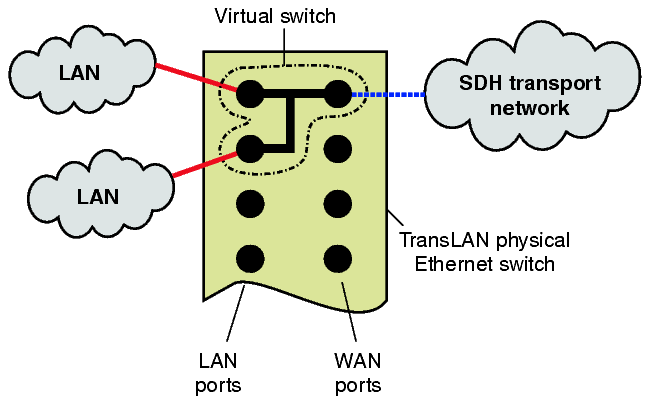
The physical L2 switch that is present on a Ethernet Interface extension card can be split into several logical or virtual switches. A Virtual Switch is a set of LAN/WAN ports on a Ethernet Interface extension card that are used by different VLAN's which can share the common WAN bandwidth. Each of the virtual switches can operate in a specific Virtual Switch mode depending on the VLAN tagging scheme.
First the VLAN tagging mode has to be specified on Ethernet Interface extension card level, this can be either IEEE 802.1Q VLAN tagging,VPN-tagging (Transparent) or 802.1ad provider bridge mode. In VPN tagging (Transparent) mode, the end-user 802.1Q VLAN tags that optionally may appear in the end user traffic are ignored in the forwarding process. These VLAN tags are carried transparently through the SDH network. In IEEE 802.1Q VLAN-tagging mode, the VLAN tags are also carried transparently, but the VLAN ID in the VLAN tags is used in the forwarding decision. Therefore end user VLAN IDs must be unique per physical switch.
Physical interfaces
The physical interface function provides the connection to the Ethernet network of the end-customer. It performs auto-negotiation, and carries out flow control.
The following physical interfaces are enabled on Alcatel-Lucent TransLAN® cards:
Important! It is recommended not to use flow control for 1000BASE-LX and 1000BASE-ZX interfaces located on the LKA12 unit.
The supported LAN interfaces for Ethernet and Fast Ethernet applications are 10BASE-T and 100BASE-TX. The numbers “10” and “100” indicate the bitrate of the LAN, 10 Mbit/s ( Ethernet) and 100 Mbit/s (Fast Ethernet) respectively. The “T” or “TX” indicates the wiring and the connector type: Twisted pair wiring with RJ-45 connectors.
Ethernet switch
The Ethernet switch connects the LAN ports with the WAN ports. It performs learning, filtering and forwarding according to the IEEE 802.1D standard.
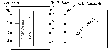
The physical Ethernet switch can be logically split in multiple, independent switches or port groups, called “virtual switch”. In the transparent tagging modes (LAN interconnect, LAN-VPN or LAN-VPN with QoS), also the name “LAN group” is used instead of “virtual switch”.
The following applies to port groups or virtual switches, respectively:
-
A virtual switch defines a spanning tree domain, and can be assigned a mode of operation (LAN interconnect, LAN-VPN or LAN-VPN with QoS).
-
A virtual switch includes any number (at least 2) of external Ethernet LAN ports and/or internal WAN ports associated with a VC-n-Xv payload.
-
Each port can be a member of only one virtual switch at a time.
-
A VLAN must have all its port members inside a single virtual switch.
In the following example, a virtual switch is provisioned that connects 2 LAN ports with 1 WAN port:

Ethernet encapsulation with GFP
The generic framing procedure (GFP) is used to adapt the asynchronous Ethernet payload to the synchronous SDH server layer.
A GFP-header (8 octets) is prepended to each Ethernet frame to indicate frame length and payload type. Gaps between Ethernet frames are filled with “IDLE” frames (4 octets each).

GFP, standardized by the ITU-T in the recommendations G.7041 and Y.1303, is a very efficient encapsulation protocol because it has a fixed and small overhead per packet.
In earlier versions (prior to the Garnet network release of June 2002) of the TransLAN® equipment, the Ethernet over SDH (EoS) encapsulation and mapping method is used for VC-12 and/or VC-3 based designs (10/100BASE-T Ethernet/Fast Ethernet cards). EoS is a proprietary encapsulation protocol, based on the ANSI T1X1.5/99-268r1 standard, and can be regarded as a precursor of GFP. EoS and GFP are both length-based encapsulation methods. EoS is similar to GFP in terms of frame delineation and mapping (incl. scrambling); differences between the two encapsulation methods lie in the size and interpretation of the EoS/GFP encapsulation core headers, as well as the length of the Idle frames.
The generic framing procedure, framed mode (GFP-F) compliant to the ITU-T Rec. G.7041 is available on all TransLAN® products since the Garnet Maintenance/Mercury network release of January 2003.
The following GFP encapsulation are possible:
VC12–Xv GFP encapsulation
The 1643 AM supports virtual concatenation of Lower Order SDH VC-12 as inverse multiplexing technique to size the bandwidth of a single internal WAN port for transport of encapsulated Ethernet and Fast Ethernet packets over the SDH/SONET network. This is noted VC12-Xv, where X = 1...5. Usage is in conformance with ITU-T G.707 Clause 11 (2000 Edition) and G.783 Clause 12.5 (2000).
This feature implies specific processing of some overhead bytes:
-
Source direction: Each individual VC-12 (from the VC12-Xv group) K4-byte (bit 1-2 multiframed) will be written to indicate the values of the multiframe indicator (timestamping), as well as the sequence indicator (individual VC-12 position inside a VC12-Xv)
-
Sink direction: Each individual VC-12 (from the VC12-Xv group) K4-byte (bit 1-2 multiframed) multi-framing indicator and sequence indicator is used to check that the differential delay between the individual VC-12s of the VC12-Xv remains within implementation limits.
Additionally, the use of G.707 Extended Signal Label is supported using V5(bits 5-7) field, in which the “101” value is written, which points to the appropriate bits of K4(bit 1) multiframe for writing in the Extended Signal Label value.
VC3–Xv GFP encapsulation
The 1643 AM supports virtual concatenation of Lower Order SDH VC-3 as inverse multiplexing technique to size the bandwidth of a single internal WAN port for transport of encapsulated Ethernet and Fast Ethernet packets over the SDH/SONET network. This is noted VC3–Xv, where X = 1,2 (SDH). Usage is in conformance with ITU-T G.707 Clause 11 (2000 Edition) and G.783 Clause 12.5 (2000) and T1X1 T1.105 Clause 7.3.2 (2001 Edition).
This feature implies specific processing of some overhead bytes:
-
Source direction; each individual VC-3 (from the VC3–Xv group) H4-byte will be written to indicate the values of the two-stage- multiframe indicator (timestamping), as well as the sequence indicator (individual VC-3 position inside a VC3–Xv)
-
Sink direction; each individual VC-3 (from the VC3–Xv group) H4-byte two-stage-multi-framing indicator and sequence indicator is used to check that the differential delay between the individual VC-3 of the VC3–Xv remains within implementation limits.
Virtual concatenation
The virtual concatenation function arranges the Ethernet frames into the right SDH virtual container. It is possible to map the client's data signal over a number of grouped virtual containers.
Related information
Please refer to Virtual concatenation for more detailed information.
LAN interfaces
1643 AM and 1643 AMS support up to four 10/100BASE-T LAN interfaces, as part of the TransLAN® Ethernet SDH Transport Solution, when the X4IP option card is used.
1643 AM and 1643 AMS support up to eight Ethernet interfaces in Private Line mode, when the X8PL option card is used. The X8PL board is a point-to-point Ethernet solution without any switching capabilities. The Ethernet ports are directly connected to the virtual concatenation groups (VCGs o flexible SDH Channel TTPs).
Main features of the X4IP and X8PL options cards
The following table lists the main features and differences of the two option cards X4IP and X8PL which can be used for Ethernet applications:
|
X4IP |
X8PL |
|---|---|
|
4 ports |
8 ports |
|
provides a Layer 2 switch |
no switch |
|
supports advanced networking applications like ring connections or point-to-multi-point connections |
cost optimized option card for point-to-point applications |
|
no LCAS (Link capacity adjustment scheme) support |
supports the LCAS (Link Capacity Adjustment Scheme) protocol (please refer to Link Capacity Adjustment Scheme (LCAS)) |
|
EoS (Ethernet over SDH) mapping or GFP (Generic Framing Procedure) |
GFP or LAPS (Link Access Procedure SDH) (please refer to Ethernet mapping schemes) |
LAN and WAN ports and VLAN
A VLAN can contain multiple LAN ports and multiple WAN ports.

Multiple LAN ports can be assigned to different VLANs, also mentioned as Virtual LAN's. This keeps the traffic on each VLAN totally separate. VLAN groups are used to connect LAN ports and WAN ports. The LAN ports are the physical 10BaseT or 100BaseT on the NE. All valid Ethernet packets are accepted (both Ethernet 2 and IEEE 802.3). The WAN ports are the logical connection points to the SDH channels. The LAN port is the interface between the customers Ethernet LAN and the Ethernet switch on the LAN unit. The WAN port is the internal port between the Ethernet switch and the part of the LAN unit where the Ethernet frame is mapped into or de-mapped from SDH payloads.
VLAN trunking
VLAN trunks carry the traffic of multiple VLANs over one single Ethernet link and allow handling off aggregated LAN traffic from multiple end users via one single high capacity Ethernet link (Fast Ethernet or Giga Ethernet) to data equipment in a Central Office or an IP Edge Router, IP Service Switch or an ATM Switch. The main benefit of VLAN trunking is that TransLAN cards can hand off end user LAN traffic via one high capacity LAN port instead of multiple low speed LAN ports.
Advantages of VLAN trunking are:
-
it permits different 802.1 tagged frames to share the same physical LAN port
-
it gives additional flexibility for egress logical WAN port assignment
-
it permits successfully routing via an aggregation function.
Learning bridges
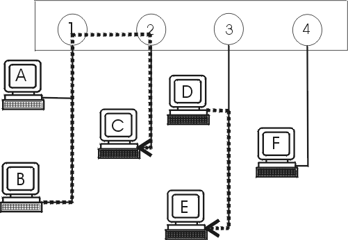
To increases the efficiency of the network, it can be separated into segments. A bridge, which may have several parts, passes packets between multiple network segments. By noting at which port an Ethernet packet with a certain source address arrives, the bridge learns to which ports a packet with a certain destination address must be sent. If the port does not know the destination address, then it will send it to all the ports except the port where it comes from. The tables which the learning bridge uses to pass the Ethernet packets to its ports are not shown to the user by the management systems.
MAC-Bridges perform automatic address learning based on the source MAC-address present in each frame.
-
In this process an unknown SA of a frame is stored together with the port number over which the frame entered the Bridge to be used when frames with that DA need to be forwarded
-
Addresses that are not refreshed (relearned) within the so-called MAC address ageing time, are removed.
In case more different source address than there is memory space are passing in an specific interval, the MAC address ageing time, addresses are prematurely flushed and possibly need to be re-learned
This causes some excess traffic as unlearned traffic is broadcasted. Too much unlearned traffic can also affect the learned traffic (because of the broadcasting).
Example

After the bridge has received a packet from station C it knows that station C is attached to port 2. When the bridge knows to which ports a station is attached, it will send packets with destination addresses of these stations only to the port the station is attached to (e.g. a packet from station B to station C is only forwarded to port 2). When a destination address of a packet is of a station in its own segment, the packet is not forwarded by the bridge (e.g. a packet from station D to station E).
Quality of service
Refer to Quality of Service (QoS) overview.
Alcatel-Lucent – Proprietary
Use pursuant to applicable agreements