Port provisioning
Customer-role and network-role ports
The user can assign a so-called “port role” to WAN ports as well as to LAN ports. In this way it is possible to forward VLAN tags , especially in double-tagging mode, also via LAN ports. Additionally it is possible to run the STP and GVRP protocols on physical LAN ports, too.
Each LAN port or WAN port can have one of the following port roles:
|
Customer role |
Customer-role ports are usually located at the edge of the switched TransLAN® network boundary, providing the Ethernet interface to the end-customer. Ethernet frames may be but need not necessarily to be tagged. In the majority of cases, LAN ports are customer-role ports. However, two LAN ports connected via an Ethernet LAN link would be an example of network-role LAN ports. Another example would be a trunking LAN port connected via an Ethernet LAN link to an ISP router (where VLAN tags are needed for further processing). |
|
Network role |
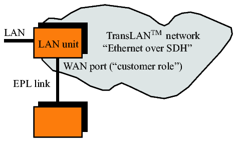
Network-role ports usually interconnect the nodes that make up the TransLAN® network. Ethernet frames need to be tagged. In the majority of cases, WAN ports are network-role ports. However, a WAN port which is connected to an Ethernet private line unit (EPL unit), thus extending the switched TransLAN® network boundary, would be an example of a customer-role WAN port. |
The following figure serves to visualize the concept of customer-role and network-role ports.
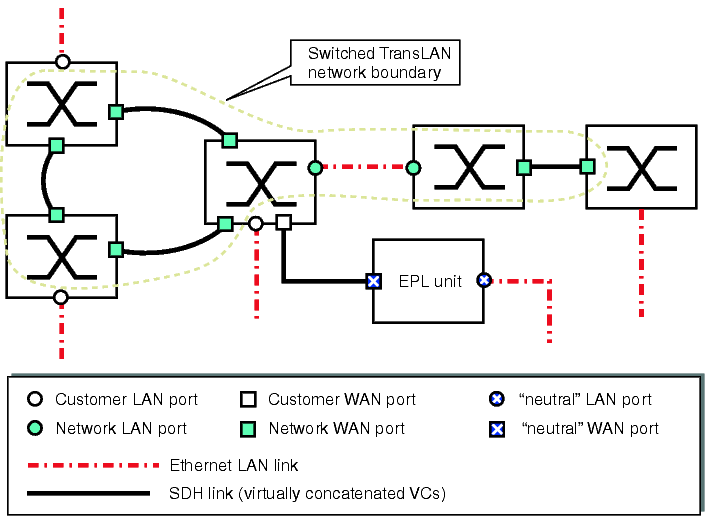
Flexible port role assignment
In most cases physical LAN ports have the customer role and physical WAN ports have the network role, but there may be exceptions in some applications. In the following figure the WAN port connects an EPL link and is therefore at the edge of the TransLAN® network. Thus it has the customer role in this case.
In the example in the figure below the VLAN tags have to be forwarded to a router. The router uses the tagging information for its switch decisions. Additionally the LAN port must fulfil a network role. In this case it behaves like a node of the TransLAN® network. It could also participate in the STP in order to avoid loops, if there was another link from a Router LAN interface to a second node within the TransLAN® network.
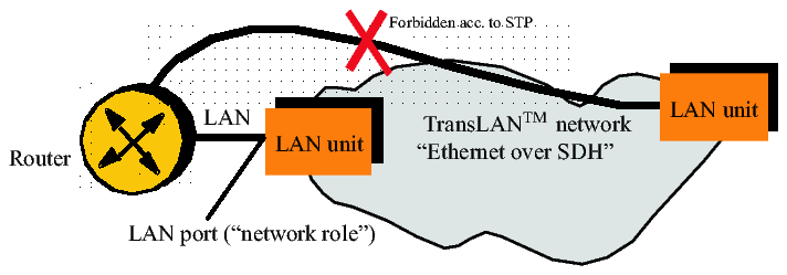
A LAN port which operates in the “network role” behaves like a WAN port in terms of VLAN tagging, STP and GVRP.
The default settings are shown in the following table
|
Physical ports | ||
|---|---|---|
|
Port role |
LAN port |
WAN port |
|
Customer role |
default |
|
|
Network role |
default | |
In the IEEE 802.1Q STP virtual switch mode and in the provider bridge mode, the port role of each LAN and WAN port can be flexibly assigned. Each LAN or WAN port can be configured to be either a customer-role or network-role port.
These are the characteristics of customer-role and network-role ports:
|
Customer-role port |
Network-role port |
|---|---|
|
In the IEEE 802.1Q STP virtual switch mode: In the ingress direction, untagged Ethernet frames are tagged with a default identifier, the port VLAN identifier (PVID). The PVID is removed from each frame at each network egress port. See also: IEEE 802.1Q VLAN tagging In the provider bridge mode: A provider bridge tag carrying a customer identifier (CID) is inserted into each Ethernet frame in the ingress direction, and removed from the frame in the reverse direction. Frames that are already tagged become double tagged. See also: IEEE 802.1ad VLAN tagging |
No tagging or untagging operations are performed. |
|
The spanning tree protocol (STP) is not supported. |
The spanning tree protocol (STP) can be enabled (default setting) or disabled. |
|
GVRP is not supported. VLAN IDs or CIDs need to be configured manually. |
GVRP can be enabled (default setting) or disabled. Dynamic VLAN IDs or CIDs of intermediate and access nodes are automatically configured if GVRP is enabled. |
|
Ingress rate control exists at customer-role ports only (see Quality of Service (QoS) overview). |
There is no rate control on network-role ports. The traffic class encoded in the p1 and p2 bits of the incoming frames is evaluated and transparently passed through. |
Fix port-role assignment in the VPN tagging modes
In all the operational modes relying on the VPN tagging mode (see Transparent tagging) the port role is fixed:
This port-role assignment in the VPN tagging modes cannot be changed. Corresponding provisioning options that might be available on the graphical user interfaces of the management systems do not apply to the VPN tagging modes and are blocked.
Repeater mode
In the repeater mode, there is no necessity to distinguish between customer-role and network-role ports, because the repeater mode can only be used in point-to-point configurations, and there is:
In the repeater mode, there is simply a LAN port and a WAN port. The LAN port provides the connection to the end-customer LAN, and the WAN port provides the connection to the SDH transport network (see Repeater mode).
Example
As an example, the following figure shows a possible network application:
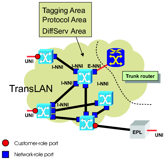
Legend:
|
UNI port |
User-Network-Interface (always a customer-role port) |
|
I-NNI port |
Internal Network-Network Interface (always a network-role port) |
|
E-NNI port |
External Network-Network Interface (here a trunking network-role port) |
Ethernet WAN port mapping
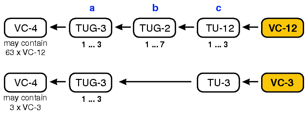
The following table shows the mapping of WAN ports to termination points (TP) for X4IP and LKA4 port units. The LKA4 port unit belongs to the former Metropolis® products. With this mapping, interworking between these products is possible. The mapping is fixed and cannot be altered. X4IP are 4-port units, whereas LKA4 is an 8-port unit. WAN ports 5 through 8 at LKA4 utilize identical mapping as respective WAN ports 1 trough 4. In case the units in service do not use the same termination points adaptation via the LO cross connect is required.
|
Capacity |
WAN port 1 / WAN port 5 |
WAN port 2/ WAN port 6 |
WAN port 3/ WAN port 7 |
WAN port 4/ WAN port 8 | ||||
|---|---|---|---|---|---|---|---|---|
|
LKA4 LJB459 |
X4IP |
LKA4 LJB459 |
X4IP |
LKA4 LJB459 |
X4IP |
LKA4 |
X4IP | |
|
100 Mbit/s |
TP100 |
TP100 |
- |
- |
- |
- |
- |
- |
|
TP200 |
TP200 |
- |
- |
- |
- |
- |
- | |
|
50 Mbit/s |
TP100 |
TP100 |
TP200 |
TP200 |
- |
- |
- |
- |
|
10 Mbit/s |
TP311 |
TP311 |
TP323 |
TP361 |
TP342 |
TP342 |
TP361 |
TP323 |
|
TP312 |
TP321 |
TP331 |
TP371 |
TP343 |
TP352 |
TP362 |
TP333 | |
|
TP313 |
TP331 |
TP332 |
TP312 |
TP351 |
TP362 |
TP363 |
TP343 | |
|
TP321 |
TP341 |
TP333 |
TP322 |
TP352 |
TP372 |
TP371 |
TP353 | |
|
TP322 |
TP351 |
TP341 |
TP332 |
TP353 |
TP313 |
TP372 |
TP363 | |
|
8 Mbit/s |
TP311 |
TP311 |
TP323 |
TP361 |
TP342 |
TP342 |
TP361 |
TP323 |
|
TP312 |
TP321 |
TP331 |
TP371 |
TP343 |
TP352 |
TP362 |
TP333 | |
|
TP313 |
TP331 |
TP332 |
TP312 |
TP351 |
TP362 |
TP363 |
TP343 | |
|
TP321 |
TP341 |
TP333 |
TP322 |
TP352 |
TP372 |
TP371 |
TP353 | |
|
6 Mbit/s |
TP311 |
TP311 |
TP323 |
TP361 |
TP342 |
TP342 |
TP361 |
TP323 |
|
TP312 |
TP321 |
TP331 |
TP371 |
TP343 |
TP352 |
TP362 |
TP333 | |
|
TP313 |
TP331 |
TP332 |
TP312 |
TP351 |
TP362 |
TP363 |
TP343 | |
|
4 Mbit/s |
TP311 |
TP311 |
TP323 |
TP361 |
TP342 |
TP342 |
TP361 |
TP323 |
|
TP312 |
TP321 |
TP331 |
TP371 |
TP343 |
TP352 |
TP362 |
TP333 | |
|
2 Mbit/s |
TP311 |
TP311 |
TP323 |
TP361 |
TP342 |
TP342 |
TP361 |
TP323 |
In accordance with the SDH multiplexing scheme, the termination point (TP) assignment of the VC-12 and VC-3 tributaries is as follows: [TPabc]
Alcatel-Lucent – Proprietary
Use pursuant to applicable agreements