Operational modes
Overview of operational modes
These TransLAN® operational modes exist:
Virtual Switch operation mode
When the transparent tagging mode has been selected on the Ethernet Interface extension card (LAN unit) level, a different Virtual Switch operational mode must be chosen per Virtual Switch. The Virtual Switch can be configured in the following operation modes:
When the IEE802.1Q/IEEE 802.1ad tagging mode has been selected, the operation mode of the Virtual Switch is always Spanning Tree.
The physical Layer 2 (L2) switch that is present on an Ethernet LAN tributary board can be split into several logical or virtual switches. A Virtual Switch is a set of LAN/WAN ports on a Ethernet LAN tributary board that are used by different VLAN's which can share the common WAN bandwidth. Each of the virtual switches can operate in a specific Virtual Switch mode depending on the VLAN tagging scheme, and each Virtual Switch mode allows specific LAN-WAN port associations as explained in the following paragraphs.
First the VLAN tagging mode has to be specified on LAN unit level, this can be either IEEE 802.1Q/IEEE 802.1adVLAN tagging or VPN tagging. In VPN tagging mode, end-user VLAN tags that optionally may appear in the end user traffic are ignored in the forwarding process. These VLAN tags are carried transparently through the "TransLAN Network". In VLAN-tagging mode, the VLAN tags are also carried transparently, but the VLAN ID in the VLAN tags is used in the forwarding decision. Therefore customers' VLAN IDs may not overlap on a physical Ethernet switch, the VLAN IDs must be unique per switch pack. (FEP 1_188_14221)
After having provisioned the tagging mode, per virtual switch a different Virtual Switch operational mode may be chosen. The Ethernet LAN tributary board supports either the Repeater mode, LAN-Interconnect, LAN-VPN, and Spanning Tree Protocol Virtual Switch mode of operation. IEEE 802.1D MAC forwarding and address filtering, multi-point bridging and spanning tree protocol (STP) are supported under all modes of operation, except the Repeater mode.
The following table gives an overview of the different modes and a list of the corresponding supported functionality:
|
VLAN Tagging Mode |
Virtual Switch Mode |
Ethertype/TPID |
QoS_CQS (Quality of Service - Classification Queueing Scheduling) |
Dynamic VLAN Registration Protocol |
Spanning Tree Implementation |
|---|---|---|---|---|---|
|
valid per pack |
valid perunit | ||||
|
VPN Tagging |
Repeater |
N/A |
N/A |
N/A |
No STP |
|
LAN Interconnect (Dedicated Bandwidth) |
N/A |
N/A |
STVRP |
Multiple STP | |
|
LAN-VPN (Shared Bandwidth) |
N/A |
N/A | |||
|
LAN-VPN with QoS |
This mode of operation is supported in previous releases. However, it is no longer supported from the 1643 Access Multiplexer AM/1643 Access Multiplexer Small AMS Release 4.0 onwards. | ||||
|
IEEE 802.1Q/IEEE 802.1ad VLAN tagging |
Spanning Tree Switched Network |
600 ... FFFF, except for 8100 |
disabled |
GVRP |
Single STP |
|
enabled | |||||
|
8100 |
enabled | ||||
|
Repeater |
600 ... FFFF, except for 8100 |
disabled |
N/A |
No STP | |
Interoperability of operational modes
Virtual Switches that are configured in the same operational mode can interwork. Virtual Switches not configured in the same operational mode do not interwork in all cases. If a Virtual Switch is configured in the “Repeater” mode or the “STP Switch” mode, it can only interwork with Virtual Switches that are configured in the same mode.
Interworking between a remote LAN-interconnect virtual switch and a VPN virtual switch is not prohibited, because the LAN-interconnect mode can be seen as a special case of the VPN mode.
Repeater mode
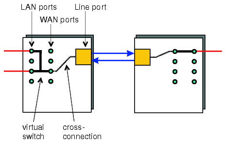
A virtual switch in repeater mode consists of exactly one LAN port and one WAN port in a fix 1:1 relationship. All Ethernet frames entering the virtual switch at a LAN port are transparently forwarded to the corresponding WAN port and transported over the network with specific limitation for X4IP described in chapter Provisioning a virtual switch in repeater (promiscuous) mode of User Operations Guide. None of the standard IEEE Std 802.1D/Q processes (MAC address learning, MAC frames forwarding and filtering, VLAN classification and filtering) applies. Received frames are relayed to the other port of the virtual switch, irrespective of their format or contents.
The WAN port that supports the Repeater mode requires the provisioning of the following parameters:
-
WAN port capacity (require manual provisioning) at 2, 4, 6, 8, 10, 50 or 100 Mbit/s
-
create cross-connections between VC-X and TU-X (where X=12 or 3).
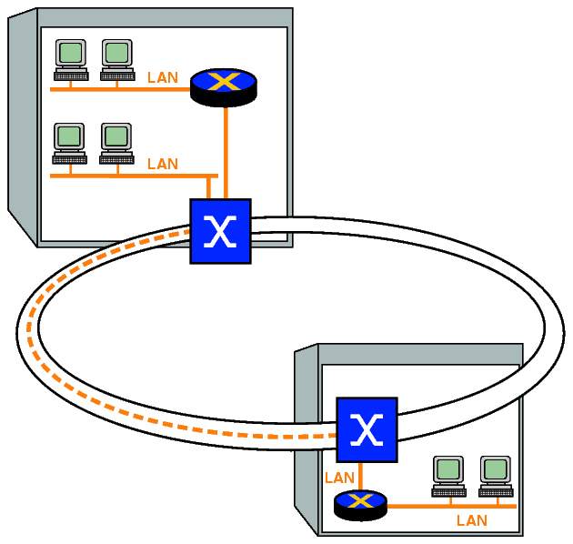
The following figure shows the network element configured in the Repeater operation mode.

A virtual switch in repeater mode emulates an Ethernet repeater except that it
Synonyms
The TransLAN® repeater mode of operation is often also referred to as “promiscuous mode” or “buffered repeater mode”.
Intended use
The repeater mode is only intended to be used in point-to-point configurations to offer a leased-lines type of service. The repeater mode is supported by E/FE as well as GbE TransLAN® cards.
Configuration rules and guidelines
Please observe these configuration rules and guidelines:
-
The use of the repeater mode is limited to virtual switches consisting of exactly one customer LAN port and one network WAN port. Only point-to-point connections are supported.
-
When a virtual switch is switched from any of the other operational modes into repeater mode, then all VLAN and QoS configuration information will be reset. When the virtual switch is switched back again into the previous mode, then these configuration settings will not become operational again but must be provisioned again.
The Ethernet packets are carried across the SDH network in a channel. Each channel comprises up to 63 VC12 or up to 2 VC3 concatenated. These VC12s and VC3s behave in the same way as normal SDH VC12s from an E1 port or SDH VC3s from an E3 port. There is some buffering in the NE, but it is still possible to lose packets because the channel bandwidth can be less than the Ethernet traffic rate.
LAN-interconnect mode
The LAN-interconnect mode of operation offers dedicated WAN bandwidth to a single end-user. Under the LAN-interconnect mode of operation, a Virtual Switch must only contain LAN ports with the same CID (Customer ID) to ensure the entire WAN port bandwidth allocated for the group is dedicated to a single end-user. Any combination of LAN- and WAN-ports is allowed, but with a minimum of two ports to be meaningful.
The following figure shows the network element configured in the LAN-interconnect operation mode.


The Ethernet packets are carried across the SDH network in a channel. Each channel comprises up to 63 VC12 or up to 2 VC3 concatenated. These VC12s or VC3s behave in the same way as normal SDH VC12s from an E1 port respectively normal SDH VC3s from an E3 port.
This operation mode support the following features:
Special case of the LAN-VPN mode
The LAN interconnect mode of operation is a special case of the LAN-VPN operation. In the LAN interconnect mode a virtual switch may contain LAN and WAN ports of a single user only.
The TransLAN® cards can support both modes of operation simultaneously as long as the corresponding virtual switches do not include the same WAN ports.
Configuration rules and guidelines
Please observe these configuration rules and guidelines:
-
On LAN ports the CID needs to be provisioned manually.
The permitted CID value range is [0 … 4094]. However, note that only values out of the value range [1 … 4094] can be used to identify a user while the value “0” cannot. The corresponding LAN port is disabled if the CID is set to “0”.
-
In the LAN interconnect mode, the virtual switch is dedicated to a single customer. Therefore, all LAN ports of a virtual switch must have the same customer identifier (CID).
-
In the LAN interconnect mode, LAN ports are always customer-role ports, and WAN ports are always network-role ports (see Port provisioning).
LAN-VPN (M-LAN) mode
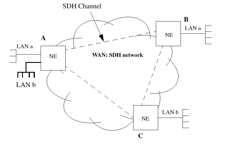
Under the LAN-VPN (Virtual Private Network) operation mode, a number of LAN- and WAN ports are grouped together to form one virtual switch. The Virtual Switch contains LAN ports of multiple end-users sharing the same WAN port(s) bandwidth. To safeguard each individual end-user's data flow and to identify an end-user's VPN from the shared WAN, the Ethernet Interface card assigns a CID to each LAN port within a Virtual Switch. The CID of each end-user (or LAN port) must be unique within a shared WAN port to create a fully independent VPN. The VPN provisioning on the WAN ports on the access and intermediate nodes is done automatically by the proprietary protocol STVRP (Spanning Tree with VPN Registration Protocol) that runs without operator intervention.
The end-users are assigned bandwidth by the operator. It allows multiple end-users to share the same SDH WAN bandwidth with each end-user being allocated a sub-VC-12-Xv (X= 1, 2, 3, 4, 5) or sub-VC-3-Xv (X=1, 2) rate of bandwidth when using the Fast Ethernet card. The combined end-user bandwidth is then mapped to the SDH time-slots and transported in the SDH network as a single data load. The minimum rate that can be configured per end-user at a LAN port is 150 kbit/s. The operator also specifies a traffic policy for each end-user.
The LAN-VPN operation mode controls the shared bandwidth by making use of the following features:
The following figure shows the network element configures in the LAN-VPN operation mode

LAN-VPN with QoS mode
Starting with release 4.0, the LAN-VPN with QoS mode, which was supported in releases prior to release 4.0, is no longer supported.
The QoS features which were supported by the LAN-VPN with QoS mode in previous releases are different to the new QoS features supported in the 1643 AM release 4.0.
VPN tagging mode
VPN tagging is used to identify user frames in the LAN-VPN mode of operation. VPN tagging is often also referred to as “transparent tagging”.
VPN tagging is characterized as follows:
-
VPN tagging is a double tagging mode. This means that a customer identifier (CID tag) is inserted into each frame at each network ingress LAN port. User frames that are already tagged become double tagged. The CID tag is removed from the frame at each network egress LAN port.
-
Ports forward only those frames that have a CID tag which “belongs” to that port (i.e. which has previously been provisioned on that port).
In the VPN tagging mode, the term “LAN group” is synonymously used to the term “virtual switch”.
Configuration rules and guidelines
Please observe these configuration rules and guidelines:
- Be aware that the port role of the LAN and WAN ports is fixed (see above):
-
The CID provisioned on each LAN port must be unique within a shared WAN to create a fully independent VPN.
The VPN provisioning on the WAN ports is done automatically by means of the proprietary spanning tree with VPN registration protocol (STVRP).
IEEE 802.1Q STP virtual switch mode
The IEE802.1Q/IEEE 802.1ad VLAN tagging scheme can be seen as an extension of the LAN-VPN mode, providing more flexibility in defining the VPN's and in general leading to a more efficient use of bandwidth. In IEEE 802.1Q VLAN tagging mode, a virtual switch is formed by a combination of LAN- and WAN ports on a physical switch that is used by different VLAN's which can share the common WAN bandwidth. Each port can be part of only one virtual switch, but a certain port may be associated with more than one VLAN. The ports that are associated with a certain VLAN ID form the VLAN Port Member Set.
On ingress, each packet is filtered on its VLAN ID. If the receiving port is a member of the VLAN to which a received MAC frame is classified, then the frame is forwarded. The user can provision whether untagged packets are dropped, or tagged with a PVID (Port VLAN ID), via the acceptable frame type parameter.
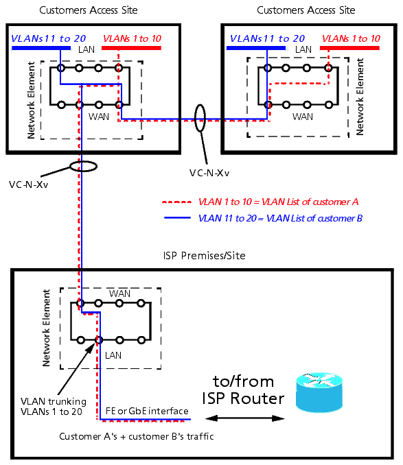
Example VLAN trunking
The VLAN trunking example shown in the next figure is one of the possible applications in this operation mode.

VLAN IDs assigned to LAN Ports should not overlap in case the operator wants to ensure Layer-2 security between those LAN Ports (in many applications, LAN Ports are likely to be dedicated to one customer). It is the responsibility of the operator to define appropriately non-overlapping VLAN IDs on all the created virtual switches.
Also the provisioned PVID, with which untagged incoming frames are tagged, should not overlap with any VLAN ID on the virtual switch of which the customers' port is part (again, this is the responsibility of the operator). Manual provisioning of intermediate nodes can be cumbersome and difficult. Therefore it is recommended to use the auto-provisioning mode for VLAN ID's on the intermediate nodes. A protocol named GVRP (GARP VLAN Registration Protocol) provides this functionality. GVRP is an application of the Generic Attribute Registration Protocol (GARP) application, which runs on top of the active spanning tree topology.
IEEE 802.1Q defines two kinds of VLAN registration entries in the Bridge Filtering Database: static and dynamic entries. In the TransLAN® implementation, static entries need to be provisioned on access node LAN ports only. GVRP will take care of configuring dynamic entries on the WAN ports of intermediate and access nodes.
A spanning tree per virtual switch is implemented. If the user wants the traffic to be protected by the spanning tree protocol and uses the manual-provisioning mode, he must make sure that the WAN ports in the alternative path also will have the corresponding VLAN IDs assigned. E.g. in a ring topology, all NE's in the ring must be provisioned with this VLAN ID. In automatic mode, the GVRP protocol will take care of the dynamic VLAN ID provisioning. The user has the possibility to flush dynamic VLAN's, thus remove dynamic VLAN's that are no longer used.
Only independent VLAN learning is supported. This means, if a given MAC address is learned in a VLAN, the learned information is used in forwarding decisions taken for that address only relative to that VLAN.
For the IEEE 802.1Q VLAN tagging mode, the oversubscription mode is not supported (cf. Quality of Service (QoS) overview).
Configurable spanning tree parameters
Even though the management system is an SDH network element manager, the data networking problems still need to be addressed when managing network elements carrying Ethernet traffic. As such the following parameters are visible/provisionable per virtual switch.
Provider bridge mode
The provider bridge mode, a double tagging mode with provisionable TPID (“Ethertype”), is - from a functional point of view - comparable to the LAN-VPN with the chief difference that the provider bridge mode is compliant to the IEEE 802.1ad standard while the VPN modes are Alcatel-Lucent proprietary modes, and that the provider bridge mode supports Quality of Service features while the LAN-VPN does not.
Traffic is forwarded based on the destination MAC address and the outer VLAN tag (S-tag).
As in the IEEE 802.1Q STP virtual switch mode, a virtual switch in the provider bridge mode is a set of LAN/WAN ports on a physical switch that are used by different VLANs which can share the common WAN bandwidth. VLANs in the same virtual switch are defined by their VLAN port member set. An instance of the spanning tree protocol runs on the WAN ports for each virtual switch.
The LAN ports and WAN ports can be configured to be customer-role or network-role ports (see Flexible port role assignment).
In the provider bridge mode, the IEEE 802.1ad VLAN tagging mode is used (see IEEE 802.1ad VLAN tagging).
Alcatel-Lucent – Proprietary
Use pursuant to applicable agreements