Ethernet over SDH applications
Purpose
This section gives an introduction to the possible TransLAN® Ethernet over SDH applications.
Types of applications
Layer-2 switching allows different types of applications, including:
TransLAN® supports all Ethernet transport solutions. Specific system configuration is required for each network application.
Direct interconnection of two LANs - Ethernet point-to-point transport
The most straight-forward Ethernet application on the TransLAN® equipment is a leased line type of service with dedicated bandwidth to interconnect two LAN segments which are at a distance that cannot be bridged by using a simple Ethernet repeater, because the collision domain size rules would be violated.
The two interconnected LANs need not be of the same speed; it is possible to interconnect a 10BASE-T and a 100BASE-T LAN this way for example.
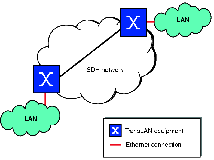
Mode of operation
Ethernet point-to-point transport can be realized by using any of the TransLAN® operational modes. However, the preferred mode of operation for the direct interconnection of two LANs is the repeater mode.
Related information
Please also refer to Repeater mode.
Ethernet multipoint transport with dedicated bandwidth
The following figure shows a network example of a multipoint Ethernet over SDH network with dedicated bandwidth:
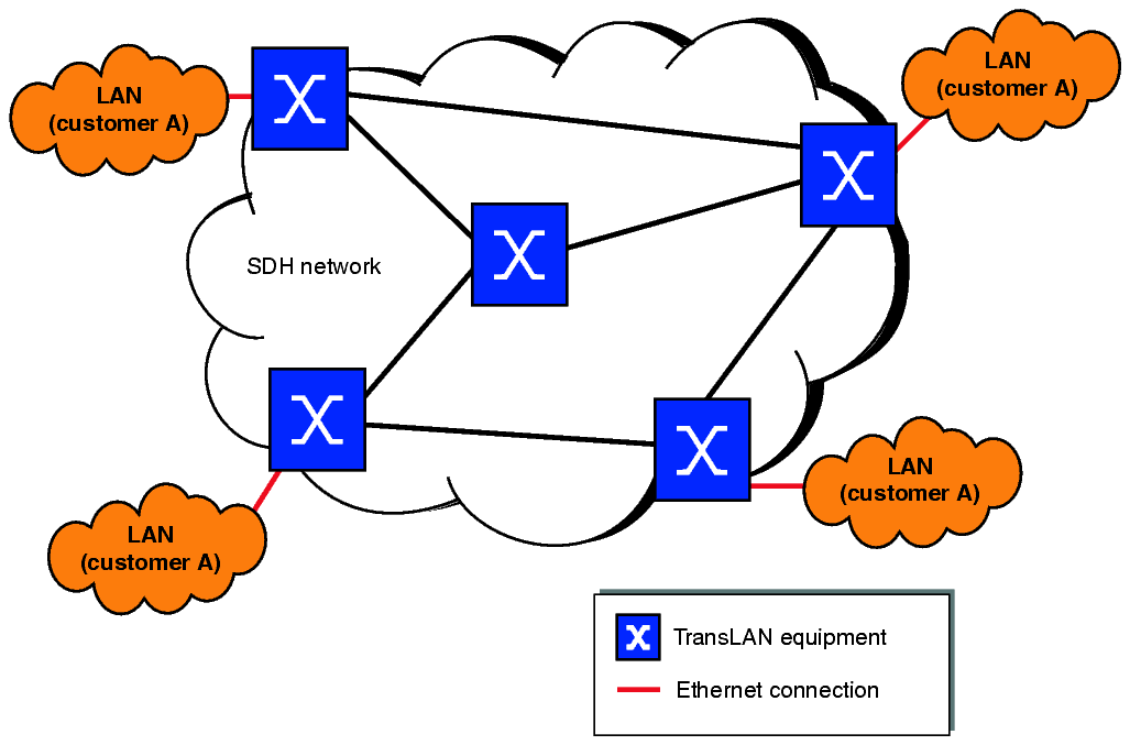
This multipoint network is dedicated to a single user.
Mode of operation
Ethernet multi-point transport with dedicated bandwidth can be realized by using any of the following TransLAN® operational modes:
Related information
Please also refer to:
Ethernet multipoint transport with shared bandwidth
The following figure shows a network example of a multipoint Ethernet over SDH network with shared bandwidth:
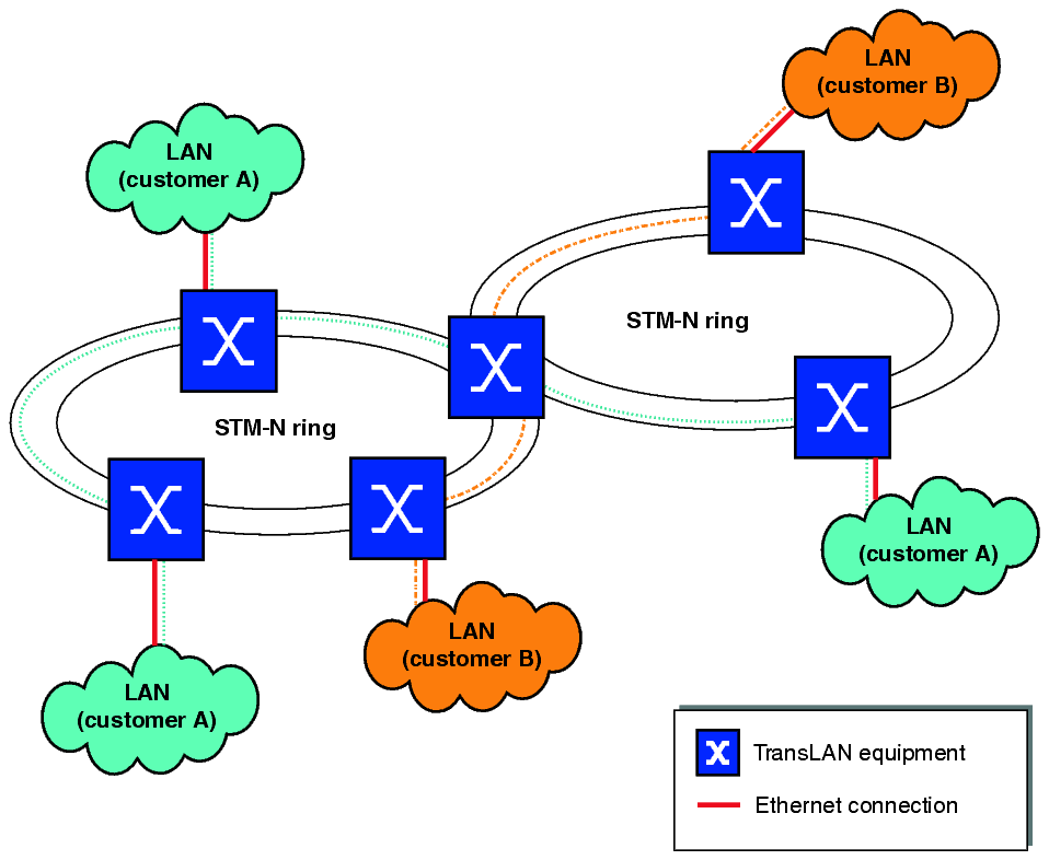
The SDH capacity is shared among more than one customer in this multipoint network. This allows customer A to use the complete SDH bandwidth at the moment that customer B is inactive, and vice versa. As Ethernet traffic is inherently bursty, sharing bandwidth can increase the efficiency of the network usage.
Isolation of the traffic of different end-users can be accomplished by using transparent tagging or VLAN tagging (see Tagging modes), depending on the desired mode of operation.
Mode of operation
Ethernet multi-point transport with shared bandwidth can be realized by using any of the following TransLAN® operational modes:
Related information
Please also refer to:
VLAN trunking
Trunking applications are a special case of Ethernet multipoint transport, either with dedicated or shared bandwidth.
Trunking applications are those applications where traffic of multiple end-users is handed-off via a single physical Ethernet interface to a router or switch for further processing. This scenario is also called “back-hauling”, since all traffic is transported to a central location, e.g. a point-of-presence (PoP) of a service provider.
Trunking applications can be classified into two topology types:
Common to both topology types is that the Ethernet traffic of multiple LANs is aggregated on one or a few well filled Ethernet interfaces, the trunking LAN interface(s). Thus, the Ethernet traffic of multiple end-users can be made available to a service provider at a central location via a limited number of physical connections. Without VLAN trunking, each end-user would need to be connected to the service provider equipment via his own Ethernet interface.
Trunking applications include the aggregation of Ethernet traffic of a single end-user as well as the aggregation of Ethernet traffic of multiple different end-users. Isolation of the traffic of different end-users can be accomplished by using transparent tagging or VLAN tagging (see Tagging modes), depending on the desired mode of operation.
A typical TransLAN® trunking application would be a configuration where many E/FE access nodes are combined with a trunking GbE hub node (cf. Distributed aggregation in the access network).
Trunking in the hub node
This figure shows an example of VLAN trunking in the hub node:
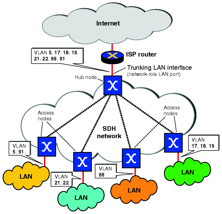
Each access node is individually connected to the hub node over a single SDH connection (or even one SDH connection per LAN port). The trunking LAN interface is a network-role LAN port. The VLAN tags in the Ethernet frames are preserved, i.e. made available to the service provider, and can thus be used for further processing.
A high WAN port density is required in the hub-node.
Averaging of the peak traffic loads of each access node (or LAN port) is not used. Each SDH link bandwidth has to be engineered for the corresponding amount of peak traffic.
Distributed aggregation in the access network
This figure shows an example of distributed aggregation in the access network:
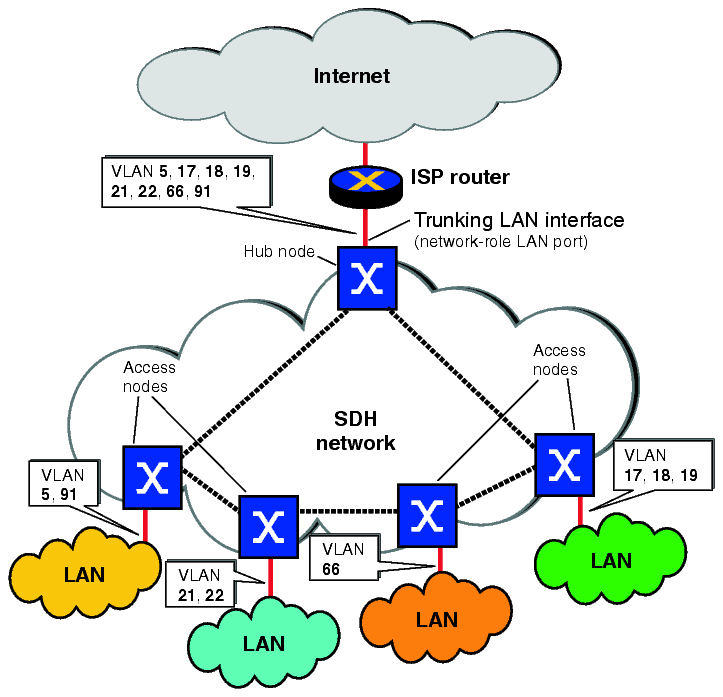
The SDH bandwidth can be shared by many end-users, which allows to gain from the statistical effects in the traffic offered by each end-user (“statistical multiplexing”). Thus, the distributed aggregation in the access network configuration is more bandwidth efficient than the trunking in the hub node topology.
Another difference is that in the trunking in the hub-node topology, the hub node has to support many WAN ports, which is not the case in the distributed aggregation in the access network configuration.
A certain bandwidth allocation fairness can be guaranteed by applying ingress rate control in the access nodes. Please note that ingress rate control is not supported on GbE TransLAN® cards but only on E/FE TransLAN® cards.
Mode of operation
Trunking applications can be realized by using any of the following TransLAN® operational modes:
Related information
Please also refer to:
Alcatel-Lucent – Proprietary
Use pursuant to applicable agreements