Cabling
Overview
This section briefly describes cabling information, including the number of particular cables required.
Cable types
The table below lists available interface cables along with the required number (if any).
Table 4-4: Interface cables
|
Cable Assembly Description |
Quantity per Shelf |
|---|---|
|
Power 1 |
1 per shelf |
|
DS1/E1 2 |
1 per Function Unit housing a 28DS1 circuit pack- LNW7 (as required) 2 per Function Unit housing 56DS1/E1-LNW8/LNW801 |
|
DS3/EC1/TransMUX12 conductors 3 |
1 per Function Unit housing an LNW16 or LNW18 circuit pack (as required) |
|
DS3/EC1/TransMUX (High-Capacity)24 conductors 3 |
2 per Function Unit housing an LNW19B or LNW20 circuit pack (as required) |
|
LAN 10/100 BASE-T |
1 per Function Unit housing a 10/100 Mbps Fast Ethernet circuit pack (as required) |
|
Gigabit Ethernet |
1 per Function Unit housing a 1000 Mbps Gigabit Ethernet circuit pack (as required to support the GbE electrical SFPs on the LNW63/64/87/170) |
|
LNW93 and LNW94 cable kit (comcode 848957437) 4 |
1 per LNW93 or LNW94 Test Pack (as desired by customer) |
Notes:
One cable assembly supports both the −48VA and −48VB main power feeders on the Alcatel-Lucent 1665 DMX shelf. Cable assemblies are available in 2, 4, 6, 10, and 14 AWG cable kits including the required Storey connectors for connection the shelf. The connectors are also available separately for customers who choose to supply their own cable.
One DS1 Cable Assembly provides one input and one output cable for 28 DS1s, i.e. for one DS1 function group, e.g.: "J1 A OUT" & "J2 A IN" used on both the standard and High-Capacity shelf. Two DS1 Cable Assemblies are required for the High-Capacity 56DS1 LNW8, i.e. for 2 function groups, e.g.: "J1 A OUT" & "J2 A IN" and "J24 A OUT" & "J24 A IN". The DS1 Cable Assembly consists of two separate cables, each containing 28 pairs of 24 gauge shielded cable. On each of the 28 pairs of cable, cable 1 is for input and cable 2 is for output.
One DS3/EC1 Cable Assembly (12 conductors) provides one input and one output cable for 12 DS3/EC-1s (LNW16) or TransMUXs (LNW18), i.e. for one "12DS3/EC-1 or TransMUX" function groups, e.g.: for "J1 A OUT" and "J2 A IN".One DS3/EC1 Cable Assembly (24 conductors) provides one input and one output cable for up to 24 signals, i.e. for the first 12 of 24 connectors used for the LNW16 or LNW18 function groups, e.g.: for "J1 A OUT" and "J2 A IN". Two assemblies are required for the High-Capacity 48DS3 (LNW19B), e.g.: "J1 A OUT" & "J2 A IN" and "J24 A OUT" & "J24 A IN".
This cable kit is an accessory to the LNW93 or LNW94 and is meant to aid in testing procedures. It is not critical to the use and function of these packs, but can help ease cabling in testing procedures. The kit contains the following cables: (1) BNC-BNC DS3 3-foot cable, (1) BNC-LCP DS3 3-foot cable, (1) Bantam-Bantam DS1 3-foot cable, (1) RJ45 - RJ45 LAN Patch Cord, (1) DB9-DB9 connector cable for the RS232 port (6 feet).
The table below lists available operations cables along with the required number (if any).
Table 4-5: Operations cables
|
Cable Assembly Description |
Quantity per Shelf |
|---|---|
|
Office Alarm 1 |
1 (bottom shelf in bay frame only) |
|
Office Alarm Mult 2 |
1 for any adjacent shelves (as required) |
|
Miscellaneous Discrete (straight connector) |
1 per shelf (as required) |
|
LAN 10/100 BaseT (Crossover) 3 |
1 per shelf (as required) |
|
LAN 10/100 BaseT (Straight Through) 3 |
1 per shelf (as required) |
|
LAN 100 BASE-T |
1 per Function Unit (as required) |
|
Sync Timing |
1 per shelf (as required) |
|
CIT Interface |
1 per shelf (as required) |
|
Modem Cable Assembly |
1 per shelf (as required) |
Notes:
One Office Alarm Cable Assembly is required for the bottom Alcatel-Lucent 1665 DMX shelf in a bay frame. Other Alcatel-Lucent 1665 DMX shelves in the bay frame do not require this assembly, but may use the Office Alarm Mult (J13) cables.
One Office Alarm Mult Cable Assembly is required for any adjacent Alcatel-Lucent 1665 DMX shelves in a bay frame (above the lowest shelf). For example, if four Alcatel-Lucent 1665 DMX shelves are located in a single 7-foot bay frame, three cable assemblies are required. These cables cannot reach any further than an adjacent shelf.
The Crossover cable is used when connecting to a PC. The Straight Through cable is used when connecting with a hub.
Ethernet faceplate cabling guidelines
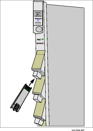
The LNW63/64/87/170 can use both optical and electrical PTM transceivers. The figure below shows the connections to the electrical PTM transceivers. The RJ45 cables that connect to the FE/GbE Electrical PTM are directed downward at a 45° angle. In order to ensure proper cable routing, the copper cables must be above any optical cables/attenuators, etc. that may be installed.
For more information on the LNW170, see 100/1000BASE-X/T (LNW170) switched Ethernet interface.
For detailed information on all PTMs available, see Allowed Ethernet/SAN PTM transceivers and the sections that follow.
Figure 4-10: LNW170 faceplate
