Procedure 11-39: Make cross-connections for LNW73/LNW73C FC-DPORT SAN transport service
 Overview
This procedure provides examples for making cross-connections for SAN transport service using the LNW73/LNW73C circuit pack.
Steps
Use this procedure as an example for making cross-connections for SAN transport service.
1 |
Use the WaveStar® CIT to log in to one of the terminating nodes. Reference: Procedure 14-2: Connect Personal Computer (PC) and establish WaveStar® CIT session |
2 |
On the System View menu, select Administration → OSI Neighbor Map command and note the NEs connected to Main 1 and Main 2. Access each of the NEs identified and select the Administration → OSI Neighbor Map command and note the NEs connected to Main 1 and Main 2. Repeat the above until the backbone ring can be sketched. For BLSR rings, you can select View → Rings → Ring Map from the System View menu, then select the 2F BLSR port protection group and click Select. Select NVMRING in the Ring Map Source selection box. You may also Display Ring Map Graph using this command. Important! If a drawing of the network is not provided with the work instructions, it is recommended that you draw a simple diagram of the ring (indicating node-to-node connections) and list each node's TID. Result: The OSI Neighbor Map window opens if the Administration → OSI Neighbor Map command was used. A list of NEs and NE neighbors is displayed if the View → Rings → Ring Map command was used. |
3 |
Verify that the system configuration is the same as specified on your work instructions. |
4 |
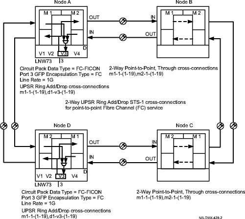
From your work instructions, determine the cross-connections to be made at each node associated with the service to be established. Figure 11-59, Point-to-point Fibre Channel service illustrates the cross-connection rate, type, and STSn AID addresses when using the Cross-Connection Wizard. |
5 |
Starting at one of the nodes in the ring for the circuit being established, select View → Cross-Connections at each node in the ring to verify that the cross-connections specified on the work instructions may be made. If cross-connections are already assigned or improperly assigned, refer trouble to the provisioning organization. Improperly assigned cross-connections may have to be deleted, or a different timeslot must be selected for the service being selected. |
6 |
One at a time, at each non terminating node, select Configuration → Cross-Connections from the System View menu to start the Cross-Connection Wizard. Use the Cross-Connection Wizard at all non terminating nodes in the network to provision the STSn pass-through cross-connections for the Ethernet service being provided. Reference: Cross-Connections for LNW73/LNW73C FC-DPORT |
7 |
One at a time, at each terminating node, select Configuration → Cross-Connections from the System View menu to start the Cross-Connection Wizard. Use the Cross-Connection Wizard at all terminating nodes in the network to provision the STSn add/drop cross-connections. Reference: Cross-Connections for LNW73/LNW73C FC-DPORT |
8 |
From the System View menu, select View → Cross-Connections at each node to verify that the proper connections have been made. |
9 |
After all cross-connections are made, click on the Alarm List button on the System View window and verify no alarms are present. |
10 |
If alarms are present, look for missing or improperly made cross-connections. Reference: Alcatel-Lucent 1665 Data Multiplexer (DMX) Alarm Messages and Trouble Clearing Guide, 365-372-302 End of steps |
Cross-Connections for LNW73/LNW73C FC-DPORT
The rate and type of VCG cross-connections made depend on the circuit pack Data Type setting (FC-FICON or ESCON) or the port GFP Enscapsulation Type setting (FC, FICON, or ASYNC-FC) when the circuit pack Data Type setting is set to FC-FICON.
Data Type: ESCON
Whan Data Type is set to ESCON (Enterprise Systems Connection) all ports on the circuit pack support only ESCON.
ESCON mode supports only full-rate service requiring a minimum of 4 STS-1s (6 STS-1s may be required for other vendor equipment), or 2 STS-3c, or 1 STS-12c cross-connections. The ports will not carry any traffic end-to-end unless the full rate is provisioned.
Data Type: FC-FICON
When Data Type is set to FC-FICON, individual port GFP Encapsulation Type may be provisioned to support three separate data protocols:
- FC (Fibre Channel) - Supports full-rate 1Gbs (1G) or 2Gbs (2G) service using STS-1 or STS-3c cross-connections. The ports will not carry any traffic end-to-end unless the full rate is provisioned.
-
Line Rate: 1G - Full-rate 1G service requires a minimum of 19 STS-1s or 6 STS-3c (7 STS-3c may be required for other vendor equipment) cross-connections.
-
Line Rate: 2G - Full-rate 2G service requires a minimum of 37 STS-1s (38 STS-1s may be required for other vendor equipment) or 12 STS-3c (13 STS-3c may be required for other vendor equipment) cross-connections.
The 2G rate only applies to ports 1 and 3. If 2G is selected for port 1(or 3), then port 2(or 4) cannot be used for service. For example, if 2G is selected for port 1 then port 2 is unused, and ports 3 and 4 could be 1G for either of the port gfptypes (FC, FICON, or ASYNC-FC).
-
- FICON (Fibre Connection) - Supports full-rate 1Gbs (1G) or 2Gbs (2G) service using STS-1 or STS-3c cross-connections. The ports will not carry any traffic end-to-end unless the full rate is provisioned.
-
Line Rate: 1G - Full-rate 1G service requires a minimum of 19 STS-1s or 6 STS-3c (7 STS-3c may be required for other vendor equipment) cross-connections.
-
Line Rate: 2G - Full-rate 2G service requires a minimum of 37 STS-1s (38 STS-1s may be required for other vendor equipment) or 12 STS-3c (13 STS-3c may be required for other vendor equipment) cross-connections.
The 2G rate only applies to ports 1 and 3. If 2G is selected for port 1(or 3), then port 2(or 4) cannot be used for service. For example, if 2G is selected for port 3 then port 4 is unused, and ports 1 and 2 could be 1G for either of the port gfptypes (FC, FICON, or ASYNC-FC).
-
- ASYNC-FC (Asynchronous Fibre Channel) - Supports full-rate or partial-rate 1Gbs (1G) or 2Gbs (2G) service using STS-1, STS-3c, or STS-12c cross-connections. Service starts as soon as any end-to-end paths are established in both directions.
-
Line Rate: 1G - Full-rate 1G service requires a minimum of 19 STS-1s or 6 STS-3c (7 STS-3c may be required for other vendor equipment) cross-connections. If STS-12c is used, then only one STS-12c cross-connection is allowed.
If the compression feature of the LNW73C is used, it typically would take only 9 STS-1s to transport the equivalent of 1Gbs full rate service. The actual compression saving depends on the data transported.
-
Line Rate: 2G - Full-rate 2G service requires a minimum of 37 STS-1s (38 STS-1s may be required for other vendor equipment) or 12 STS-3c (13 STS-3c may be required for other vendor equipment) cross-connections. If STS-12c is used, then only one STS-12c cross-connection is allowed.
The 2G rate only applies to ports 1 and 3. If 2G is selected for port 1(or 3), then port 2(or 4) cannot be used for service. For example, if 2G is selected for port 1 then port 2 is unused, and ports 3 and 4 could be 1G for either of the port gfptypes (FC, FICON, or ASYNC-FC).
If the compression feature of the LNW73C is used, it typically would take only 18 STS-1s to transport the equivalent of 2Gbs full rate service. The actual compression saving depends on the data transported.
-
Cross-connections
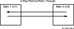
Add/drop or pass-through cross-connections are established between the source and destination in a ring. Figure 11-56, 2-Way Point-to-Point, Through cross-connection illustrates a 2-way pass-through cross-connection from one side of the ring to the other.
Figure 11-56: 2-Way Point-to-Point, Through cross-connection

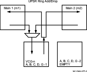
Figure 11-57, UPSR Ring Add/Drop cross-connection illustrates an add/drop cross-connection on a UPSR ring.
Figure 11-57: UPSR Ring Add/Drop cross-connection

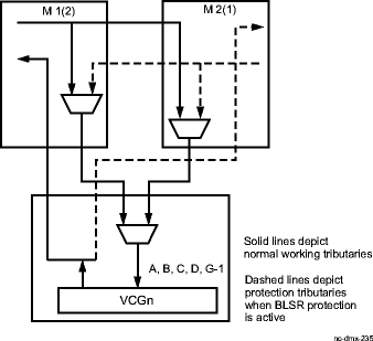
Figure 11-58, 2F BLSR Add/Drop cross-connection illustrates an add/drop cross-connection on a BLSR ring.
Figure 11-58: 2F BLSR Add/Drop cross-connection

Figure 11-59: Point-to-point Fibre Channel service
