Cross-Connections for Ethernet
Cross-Connections for Ethernet
Cross-connections supporting Ethernet services vary according to the type of circuit pack being used:
-
LNW63/64 GBE-PL Ethernet circuit packs support STS1, STS3c, or STS12c cross-connections.
-
LNW87 FE/GBE-PL Ethernet circuit pack supports STS1, STS3c, or STS12c cross-connections.
-
LNW66/67/68 Ethernet circuit packs support STS1 cross-connections.
-
LNW70/LNW170 100/1G-FXS Ethernet circuit packs support STS1, STS3c, or STS12c cross-connections.
-
LNW71 10/100-PL Ethernet circuit packs support STS1 and STS3c cross-connections.
-
LNW74 10/100-T/F Ethernet circuit packs support STS1, STS3c, and VT1.5 cross-connections.
-
LNW78 100/1G-FSR Ethernet circuit packs support STS1, STS3c, or STS12c cross-connections.
LNW63/64/87 Ethernet circuit packs:
For the LNW63/64/87 Ethernet circuit packs, each Ethernet virtual concatenation group (VCG) may have from 1 to 21 STS1s cross-connected to support the bandwidth assignment. For the LNW63 or LNW87, when used with non-VLF main circuit packs, the total circuit pack port capacity is 48 STS1s. For the LNW64/LNW87, the total circuit pack port capacity is 168/84 STS1s when used with VLF main circuit packs. The maximum capacity may be divided among the VCGs.
Cross-connect rates:
LNW66/67/68 Ethernet circuit packs:
For the LNW66/67/68 Ethernet circuit packs, each Ethernet virtual concatenation group (VCG) may have from 1 to 21 STS1s cross-connected to support the bandwidth assignment.
LNW70/LNW170 Ethernet circuit packs:
-
STS1 Ethernet Cross Connect Mode – LNW70/LNW170 Ethernet circuit packs in STS1 cross connect mode support up to 48 STS1s to individual VCGs with the following restrictions:
-
STS12c Ethernet Cross Connect Mode – LNW70/LNW170 Ethernet circuit packs in STS12c cross connect mode support one STS12c or virtual concatenation (VCAT) of up to 16 STS3c cross-connections with restrictions. The STS1 numbers used for STS3c cross-connects may be 1, 4, 7, 10, 13, 16, 19, 22, 25, 28, 31, 34, 37, 40, 43, 46.
Individual VCGs have the following restrictions:-
VCG 1-2 ― Supports VCAT of up to 16 STS-3Cs or one STS-12c. The highest number of STS-3C that can be used in the order of 1, 4, 7, ... is 46.
-
VCG 3-28 ― Supports VCAT of up to 10 STS-3Cs or one STS-12c. The highest number of STS-3C that can be used in the order of 1, 4, 7, ... is 28.
-
VCG 29-32 ― Supports VCAT of up to 3 STS-3Cs. The highest number of STS-3C that can be used in the order of 1, 4, 7, ... is 7.
-
VCG Usage:
-
NOTAG VLAN Tagging Mode – When the LNW70/LNW170 is used in Private Line (NOTAG) mode, there are 8 VCG’s and there is a fixed mapping between 8 Ethernet ports and VCG ports: LAN-1 maps to VCG-1, etc.
-
SWITCHED VLAN Tagging Mode – When the LNW70/LNW170 is used in SWITCHED mode, there are 32 VCG’s. Cross-connections are established in the same way as in the NOTAG mode but there is no fixed mapping between LAN ports and VCGs.
LNW71 10/100-PL Ethernet circuit packs:
-
STS1 Ethernet Cross Connect Mode – For the LNW71 10/100-PL circuit pack, one or two STS1 cross-connections may be made to each of the 24 VCGs in STS1 mode. In STS1 mode, the first STS1 cross-connection made to a VCG should be made to the first (1) STS1 tributary of the VCG.
-
STS3c Ethernet Cross Connect Mode – In STS3c mode, at most one STS-3c or one STS-1 cross-connection may be made to each of the first 16 VCGs (1-16), (VCGs 17-24 are not used). In STS3c mode, if an STS1 cross-connection is made to a VCG, it must be made to the first (1) STS1 tributary of the VCG.
LNW74 10/100-T/F Ethernet circuit packs:
-
VT Virtual Concatenation = 0 – LNW74 10/100-T/F Ethernet circuit packs with VT Virtual Concatenation set to 0 does not allow VT mapping and all 48 STS-1s are available for STS-1 VCAT and STS-3c. One to three STS-1s or one STS-3c may be assigned to each of the 24 VCGs up to the total capacity of 48 STS1s for the circuit pack.
-
VT Virtual Concatenation = 12 – LNW74 10/100-T/F Ethernet circuit packs with VT Virtual Concatenation set to 12 allows VT mapping with 12 STS-1s reserved for VT mapping. The remaining 36 STS-1s are then available for STS-1 VCAT or STS-3c. Up to 336 VT1.5s may be used with up to 63 assigned to any VCG.
Ports may be provisioned until all the available 48 STS-1 equivalent bandwidth (including VT1.5s) is used.
LNW78 100/1G-FSR Ethernet circuit packs:
-
STS1 Ethernet Cross Connect Mode – Supports virtual concatenation of STS1s up to a maximum of 24 STS1s cross-connected to each VCG.
-
STS12c Ethernet Cross Connect Mode – Supports virtual concatenation of up to 8 STS3c or one STS12c to each VCG.
Important rules for cross-connections
Ethernet cross-connections tie together VCG tributaries in two or more Ethernet circuit packs through SONET STS-1 tributaries. For example, a cross-connection of m1-1-1 to d1-v1-1 at Node A, and a cross-connection of m1-1-1 to g1-v1-5 at Node B ties d1-v1-1 (VCG1, tributary 1) at Node A to g1-v1-5 (VCG1, tributary 5) at Node B.
When more than one VCG STS1 tributary is being cross-connected to provide an Ethernet service, the order in which the VCG tributaries are connected must be the same at both ends of a span. If the order is not correct, transmission will not be established. See examples below.
For multiple VCG STS1 tributary cross-connections, it is strongly suggested that VCG tributary cross-connections begin at VCG STS1 tributary #1, then VCG tributary #2, and so forth to the last cross-connection. It is also suggested that the VCG tributary cross-connections be made in an increasing (ascending) order at each end of the span as shown in the example that works.
This example works:
|
NODE A |
NODE B |
|
d1-v1-5 <-> m1-1-1 |
m1-1-1 <-> g1-v1-1 |
|
d1-v1-6 <-> m1-1-2 |
m1-1-2 <-> g1-v1-2 |
|
d1-v1-7 <-> m1-1-3 |
m1-1-3 <-> g1-v1-3 |
This example does not work:
|
NODE A |
NODE B |
|
d1-v1-5 <-> m1-1-1 |
m1-1-1 <-> g1-v1-3 |
|
d1-v1-6 <-> m1-1-2 |
m1-1-2 <-> g1-v1-2 |
|
d1-v1-7 <-> m1-1-3 |
m1-1-3 <-> g1-v1-1 |
For the LNW66/67/68 Ethernet circuit packs, a VCG alarm (indicating a tributary mismatch) would be raised in the case of the above example that does not work and transmission would not be established.
For the LNW71 10/100-PL circuit pack, transmission would not be established, but no alarm is raised to indicate a tributary mismatch.
Cross connect types
This section uses WaveStar® CIT Cross-Connection Wizard commands to describe some considerations when using path protected and unswitched cross-connections. Path protected cross-connections in this section include UPSR Ring Add/Drop, 2F BLSR Add/Drop, and 2-Way Point-to-Point, Through. Unswitched cross-connections are Multipoint.
Cross-connection provisioning using TL1 commands requires the use of multiple 1way, 1 waypr, and 1way unswitched cross-connections to make the appropriate cross-connections. Multipoint equivalent TL1 cross-connections are provisioned using four 1way unswitched cross-connections. UPSR Ring Add/Drop equivalent TL1 cross-connections are provisioned using two 1way and one 1waypr cross-connections. 2F BLSR Add/Drop and 2-Way Point-to-Point, Through equivalent TL1 cross-connections are provisioned using two 1way cross-connections.
Multipoint (unswitched) Cross-connections for LNW63/64/70/87 circuit packs
For the LNW63/64/87 and LNW70/LNW170 in NOTAG mode there is a fixed mapping between the Ethernet ports and VCG ports. Any VCG can be connected to either main slot. For the LNW63/64/70/87, there is no pairing of the VCGs when using multipoint cross-connections. For the LNW70/LNW170 in Switched mode, there is no fixed mapping between VCGs and LAN ports.
Multipoint (unswitched) Cross-connections for LNW66/67/68 circuit packs
Multipoint cross-connections are made by specifying an odd VCG number. The paired (next higher number) VCG is then automatically cross-connected. For example, when a Multipoint connection is made to an STS trib in VCG1 (e.g. a1-v1-1), a connection is automatically made internally to the corresponding STS trib in VCG2 (e.g. a1-v2-1). VCG v2 and associated trib then become unavailable for other connections. For the LNW67/68 circuit packs, when a connection is made to an STS trib in VCG3, a connection is automatically made internally to the corresponding STS trib in VCG4. VCG v4 and associated trib then become unavailable for other connections.
The timeslot on the odd VCG is connected to Main-1 (West in case of a ring) and the same timeslot on the next higher (even) VCG is connected to Main-2 (East in case of a ring).
Multipoint (unswitched) Cross-connections for LNW71 circuit packs
In STS1 cross-connect mode, multipoint cross-connections may be made to all 24 VCGs. When a multipoint cross-connection is made to an STS trib in VCG "n", where n=1-12, (for example, v3), a connection is automatically made internally to the corresponding STS trib in VCG "n+12" (for example, v15).
In STS3c cross-connect mode, multipoint cross-connections may be made to the first 16 VCGs (1-16). When a multipoint cross-connection is made to an STS trib in VCG "n", where n=1-8, (for example, v2), a connection is automatically made internally to the corresponding STS trib in VCG "n+8" (for example, v10).
Multipoint (unswitched) Cross-connections for LNW74 circuit packs
The LNW74 circuit pack does not support multipoint cross-connections.
Multipoint (unswitched) Cross-connections for LNW78 circuit packs
Any VCG can be connected to either main slot. There is a fixed mapping between the RPR IF and the VCG pairs. The RPR IF is addressed using the odd-numbered VCG of the pair. In this release, there is only one RPR IF, VCG v1.
Path protected (add/drop) cross-connections for LNW66/67/68 circuit packs
When a path protected connection is made to an STS trib in VCG1, then VCG2 is unused and unavailable for any connection. For LNW67/68 circuit packs, when a path protected connection is made to an STS trib in VCG3, then VCG4 is unused and unavailable for any connection.
Path protected (add/drop) Cross-connections for LNW63/64/70/87 circuit packs
There is no pairing of SONET-protected cross-connections, any available VCG can be used.
Path protected (add/drop) Cross-connections for LNW71 circuit packs
Path protected cross-connections may be made to all 24 VCGs in STS1 mode. In STS3c mode, cross-connections may be made to all of the first 16 (1-16) VCGs.
Path protected (add/drop) cross-connections for LNW74 circuit packs
Cross-connections may be made to all 24 VCGs. One to three STS-1s or one STS-3c may be assigned to each of the 24 VCGs up to the total capacity of 48 STS1s for the circuit pack. When VT Virtual Concatenation is set to 12, up to 336 VT1.5s may be used with up to 63 assigned to any VCG.
Path protected (add/drop) Cross-connections for LNW78 circuit packs
The LNW78 circuit pack does not support path protected cross-connections.
Path protected (add/drop, pass-through) cross-connections
Path protected cross-connections using the WaveStar® CIT Cross-Connection Wizard request a two-way add/drop or pass-through cross-connection be established between the source and destination in a ring.
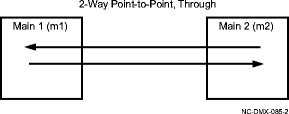
Figure 11-39, 2-Way Point-to-Point, Through cross-connection illustrates a pass-through cross-connection from one side of the ring to the other.
Figure 11-39: 2-Way Point-to-Point, Through cross-connection

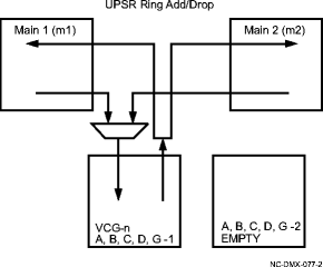
Figure 11-40, UPSR Ring Add/Drop cross-connection illustrates an Ethernet 2waypr add/drop cross-connection on a UPSR ring.
Figure 11-40: UPSR Ring Add/Drop cross-connection

Figure 11-41, FE to GbE 2-Way Hairpin cross-connection illustrates a 2waypr hairpin cross-connection between a Fast Ethernet circuit pack and a Gigabit Ethernet circuit pack.
Figure 11-41: FE to GbE 2-Way Hairpin cross-connection

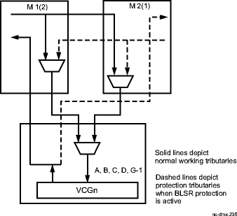
Figure 11-42, 2F BLSR Add/Drop cross-connection illustrates an Ethernet 2-way add/drop cross-connection on a BLSR ring.
Figure 11-42: 2F BLSR Add/Drop cross-connection

Multipoint (unswitched)
A multipoint (unswitched) cross-connection is established between the source and destination in a non-path switched ring configuration. The Multipoint cross-connect type can only be selected if an Ethernet interface is being addressed. When an Ethernet interface is multipoint cross-connected, the signal locking mechanism is provided.
Figure 11-43, Multipoint (unswitched) cross-connection illustrates a multipoint cross-connection.
Figure 11-43: Multipoint (unswitched) cross-connection
