Procedure 11-33: Provision LCAS, add/enable/remove tributaries
 Overview
Use this procedure to enable/disable LCAS or add/enable/remove tributaries to LCAS-enabled VCGs.
LCAS allows for in-service hitless addition or removal of tributary members of a Virtual Concatenation Group (VCG) to vary its bandwidth. It also allows for automatic removal and restoration of failed members.
Tributary members may be any supported SONET tributary rate (e.g. STS-1, STS-Nc, VT1.5 tributaries) but never a mix of rates. When a trib is added which is tardier than current members, the entire VCG is retarded to allow it to join. This is accomplished by a temporary decrease in the output payload rate, while the current members are buffered for time-alignment.
The LCAS protocol is unidirectional in that the source side controls the hitless operations. The sink side only assists by indicating whether it is ready and acknowledging completion. This means that LCAS requires a return path for signaling from the sink back to the source. Single one-way cross-connections will not provide a return path. Therefore, for each span, two-way cross-connections must be made. Then, in order to be hitless, removal operations must be sequenced between the two ends, always starting at the source side of each unidirectional link.
Important!
LCAS and this procedure apply only to LNW63, LNW64, LNW70/LNW170, LNW74, LNW87 and LNW78 Ethernet circuit packs. If only one end has LCAS enabled or the far end does not support LCAS, transmission operates normally in the non-LCAS mode. The standing condition NOTLCAS is generated when LCAS is enabled but the far end is detected as not supporting LCAS. It is cleared either when LCAS is disabled locally or the far end is detected to support LCAS.
 Before you begin
Prior to performing this procedure, refer to Before you begin and Required equipment in this chapter and you must have complete work instructions for this procedure that detail:
Steps
1 |
Determine the VCGs at each terminating end (source and sink) of the circuit being provisioned. For example:
| ||||||||||
2 |
| ||||||||||
3 |
ENABLE/DISABLE LCAS FOR SELECTED VCGs Determine the VCGs at each end (source and sink) of the circuit being provisioned. | ||||||||||
4 |
Use the WaveStar® CIT to log in to the Alcatel-Lucent 1665 DMX shelves. Reference: Procedure 14-2: Connect Personal Computer (PC) and establish WaveStar® CIT session | ||||||||||
5 |
Use the Configuration → Equipment command from the System View menu, select the circuit pack, then select the VCG port being provisioned. Click Select. Important! Changing between LCAS-Enabled to LCAS-Disabled on an in-service VCG may not be hitless. | ||||||||||
6 |
Click on the LCAS tab. Provision the LCAS parameters, as required. Or, use the ed-vcg TL1 command to provision the LCAS parameters. LCAS parameters:
LCAS and non-LCAS interworking is supported but the change between LCAS enabled/disabled and LCAS disabled/enabled may not be hitless. Reference: Procedure 11-12: Provision Ethernet VCG parameters | ||||||||||
7 |
Repeat from Step 4 for each VCG port being provisioned. END OF STEPS TO ENABLE OR DISABLE LCAS. | ||||||||||
8 |
ADDING TRIBUTARIES Use the WaveStar® CIT to log in to the Alcatel-Lucent 1665 DMX shelf, as required. Reference: Procedure 14-2: Connect Personal Computer (PC) and establish WaveStar® CIT session | ||||||||||
9 |
Make all required pass-through and add/drop cross-connections, if not already performed. The cross-connections providing transmission between the Source and Sink VCG’s can occur at any time. Similarly the Source and Sink can be activated in any order. Only when all components are in place and enabled does the tributary member get added. Tributaries may be enabled (default) when the cross-connections are made or disabled and then enabled at a later time. Procedure 11-24: Make cross-connections for Ethernet service END OF STEPS FOR ADDING TRIBUTARIES. | ||||||||||
10 |
ENABLING TRIBUTARIES Use the WaveStar® CIT to log in to the Alcatel-Lucent 1665 DMX shelf, as required. | ||||||||||
11 |
Use the Configuration → Equipment command from the System View menu, select the Ethernet circuit pack, select the VCG port, then select the tributary (Trib) being provisioned. Click Select. Or, use the ed-vcgtrib TL1 command to provision parameters. | ||||||||||
12 |
In the Tributary provisioning screen, select Enabled for the VCG Membership for both the Input (Source) and Output Direction (sink). When Input VCG Membership (source) (inmbs) is enabled, the VCG tributary is a member of the VCG in the source direction (towards the SONET network). When Output VCG Membership (sink) (outmbs) is enabled, the VCG tributary is a member of the VCG in the sink direction (away from the SONET network). | ||||||||||
13 |
Repeat from Step 10 to Enable Membership for each Tributary at each VCG in each add/drop node in the configuration. In a multipoint configuration, it is suggested that tributary membership be added at both ends on one link before moving to the next link. END OF STEPS FOR ENABLING TRIBUTARIES. | ||||||||||
14 |
Service hits may occur if the proper sequence is not followed when removing tributaries from an LCAS enabled system. REMOVING TRIBUTARIES Use the WaveStar® CIT to log in to the near-end Alcatel-Lucent 1665 DMX shelf, as required. Reference: Procedure 14-2: Connect Personal Computer (PC) and establish WaveStar® CIT session | ||||||||||
15 |
From the System View menu, use the Configuration → Equipment command from the System View menu, select the Ethernet circuit pack, select the VCG port, then select the tributary (Trib) being removed. Click Select. Or, use the ed-vcgtrib TL1 command to provision parameters. | ||||||||||
16 |
In the Tributary provisioning screen, select Disabled for the VCG Membership for the Input Direction (Source). | ||||||||||
17 |
Use the WaveStar® CIT to log in to the far-end Alcatel-Lucent 1665 DMX shelf terminating the link. | ||||||||||
18 |
From the System View menu, use the Configuration → Equipment command from the System View menu, select the Ethernet circuit pack, select the VCG port, then select the tributary (Trib) being removed. Click Select. Or, use the ed-vcgtrib TL1 command to provision parameters. | ||||||||||
19 |
In the Tributary provisioning screen, select Disabled for the VCG Membership for both the Output Direction (Sink) and Input Direction (source). | ||||||||||
20 |
Use the WaveStar® CIT to log back in to the near-end Alcatel-Lucent 1665 DMX shelf in which you started. | ||||||||||
21 |
From the System View menu, use the Configuration → Equipment command from the System View menu, select the Ethernet circuit pack, select the VCG port, then select the tributary (Trib) being removed. Click Select. Or, use the ed-vcgtrib TL1 command to provision parameters. | ||||||||||
22 |
In the Tributary provisioning screen, select Disabled for the VCG Membership for the Output Direction (Sink). | ||||||||||
23 |
If you are removing tributaries in a multipoint configuration, repeat from Step 14 for each link having tributaries removed. Repeat these steps for all other tributaries being removed. | ||||||||||
24 |
If required, remove all pass-through and terminating cross-connections relating to the removed tributaries. End of steps |
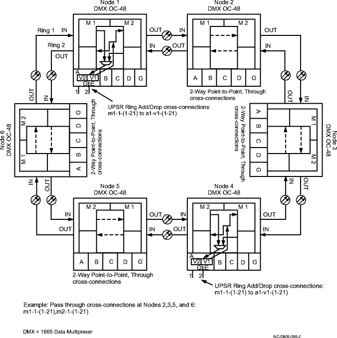
Figure 11-50: 2-way cross-connections on a UPSR

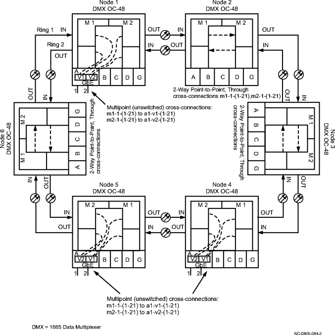
Figure 11-51: Multipoint GbE cross-connections on a UPSR
