Procedure 11-26: Change an existing spanning tree configuration
 Overview
This procedure provides an example of how to change an existing spanning tree configuration by changing the spanning tree path cost at one of the nodes.
This procedure might be used if traffic patterns change and dictate that a reconfiguration would provide more efficient service.
 Privilege level
You must login as either a Privileged or General user to complete this procedure.
Safety precautions
To assure both personal safety and the proper functioning of the Alcatel-Lucent 1665 Data Multiplexer, it is imperative to review and understand these warnings and precautions prior to performing this procedure.
|
NOTICE Service-disruption hazard |
A minimal amount of service interruption may be encountered when performing this procedure.
Be sure to follow your work instructions in performing this procedure.
 Before you begin
Before you begin this procedure, you should:
-
Refer to Before you begin and Required equipment in this chapter.
-
Know which nodes in the network are participating in the spanning tree configuration for the service being configured.
-
Have a knowledge of Ethernet services and spanning tree configurations.
-
Have detailed work instructions for performing this procedure.
-
Know which span in the spanning tree configuration is normally blocked and which span you are going to reconfigure as blocked.
-
Know which node is the root node (root bridge) in the configuration.
-
Know the spanning tree group ID (stgrpid) of the spanning tree group being reconfigured.
Steps
Use this procedure as an example to reconfigure an existing spanning tree configuration.
1 |
Use the WaveStar® CIT to log in to a terminating Alcatel-Lucent 1665 DMX shelf. Reference: Procedure 14-2: Connect Personal Computer (PC) and establish WaveStar® CIT session |
2 |
On the System View menu, select Administration → OSI Routing Map or Administration → OSI Neighbor Map to retrieve a node-to-node listing of every node in the network. Important! If a drawing of the network is not provided with the work instructions, it is recommended that you draw a simple diagram of the ring (indicating node-to-node connections) and list each node's TID. Result: The OSI Routing Map or OSI Neighbor Map window opens. |
3 |
Verify that the system configuration is the same as specified on your work instructions. |
4 |
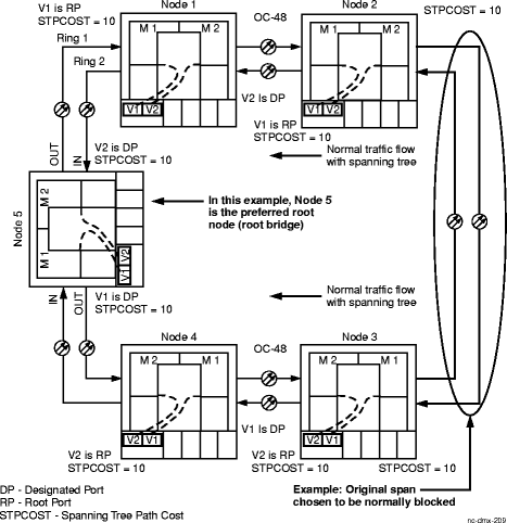
From your work instructions and the network map, determine the nodes in the ring at which Ethernet services are provided and are part of the same spanning tree group. Figure 11-46, Existing spanning tree configuration for an example. |
5 |
Use the rtrv-stgrp command or the View → Data → Spanning Tree Group command from the System View menu at each node to determine which node is the root node (root bridge), the spanning tree root path cost (strtpcost), the VCG spanning tree port role (stprole), and the VCG spanning tree path cost (stpcost) for each VCG AID in the spanning tree group. Make a note of these parameter values at each node. Reference: See Figure 11-46, Existing spanning tree configuration. Assuming VCGs v1 and v2 are used at each node, if you logged into Node 5, the root bridge, you should see a root path cost of zero (0), and each VCG port would have a port role of Designated. At Nodes 1 and 2, you should see Port Roles for VCG v1 at both nodes as being root port, indicating traffic toward the root bridge. At Nodes 3 and 4, you should see Port Roles for VCG v2 at both nodes as being root port, indicating traffic toward the root bridge. |
6 |
PRINCIPLES OF SPANNING TREE AND PORT COST Refer to Figure 11-46, Existing spanning tree configuration and read the following to understand how spanning tree blocks a span: To have spanning tree block a span, the spanning tree root path cost is set equally at the two bridges (nodes) at each end of the blocked span. The spanning tree root path cost (strtpcost) at a node (bridge) is the sum of the path costs of the root port VCGs that connect the node to the root node. Assume that in the original configuration the spanning tree path cost (stpcost) for each VCG is set to the default of 10 at each node. Node 2 is connected to root Node 5 through VCG v1 at Node 2 and VCG v1 at Node 1. Therefore, the root path cost of Node 2 is 20, which is the sum of the path costs of Node 2 VCG v1 and Node 1 VCG v1 (10 + 10 = 20). Node 3 is connected to root Node 5 through VCG v2 at Node 3 and VCG v2 at Node 4. Therefore, the root path cost of Node 3 is also 20, which is the sum of the path costs of Node 3 VCG v2 and Node 4 VCG v2 (10 + 10 = 20). |
7 |
Assume that your traffic studies indicate a more efficient service would be obtained by blocking the span between Node 3 and Node 4 instead of the presently blocked span between Node 2 and Node 3. |
8 |
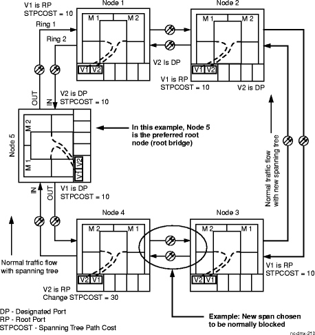
HOW TO CHANGE PATH COST TO RECONFIGURE SPANNING TREE To change the spanning tree configuration to block the span between Nodes 3 and 4, we need to have the root path cost of Node 3 and Node 4 set equally. We can increase the spanning tree path cost (stpcost) at the root port (VCG v2) on Node 4. To change the path cost, use either the ed-vcg command or selectConfiguration → Equipment from the System View menu, expand the details for the circuit pack, select the VCG, then click on the Spanning Tree tab. Change the value in the Spanning Tree Path Cost box, then click Apply. Reference: Refer to Figure 11-47, New spanning tree configuration. If the span between Nodes 3 and 4 is going to be blocked, then Node 3 will be connected to root Node 5 through Node 3 VCG v1, Node 2 VCG v1, and Node 1 VCG v1. The root path cost at Node 3 will then be 30, the sum of the path costs of root port VCG v1 at Nodes 3, 2, and 1 (10 + 10 +10 = 30). We need to ensure the root path cost at Node 4 is also 30. Note that Node 4 is connected to root Node 5 only through Node 4's VCG v2. If we increase the path cost at Node 4 VCG v2 to 30, then the root path cost at Node 4 will also be 30. Since the root path cost at Node 4 is now equal to the root path cost at Node 3, the span between Nodes 3 and 4 will be blocked. End of steps |
Figure 11-46: Existing spanning tree configuration

Figure 11-47: New spanning tree configuration
