Procedure 12-16.3: Upgrade or replace SYSCTL (LNW2) circuit pack using FTP
 Overview
Use this procedure to replace an LNW2 using File Transfer Protocol (FTP).
Important!
You must have direct TCP/IP connectivity to your NE and the NE must have a defined IP address.
 Required equipment
Refer to Required equipment in Procedure 12-16: Upgrade or replace SYSCTL (LNW2) circuit pack for a list of equipment required to perform this procedure.
 Before you begin
Prior to performing this procedure, complete Procedure 12-16: Upgrade or replace SYSCTL (LNW2) circuit pack.
Steps
Complete the following steps to replace your SYSCTL using FTP.
1 |
From the System View menu, select Configuration → Software → Remote Backup. | ||||||||||||||||||||||||||||||||||
2 |
In the pull-down Backup To/Via: menu, select FTP. | ||||||||||||||||||||||||||||||||||
3 |
Select the connection from the Profile pull-down menu and proceed to Step 5. OR Enter information for a new profile as follows:
| ||||||||||||||||||||||||||||||||||
4 |
If you entered connection information in Step 3 and wish to keep the information for future backups: Entries to the Profile pull-down menu may be changed using the Modify, Apply, and Save buttons or removed using the Delete button. | ||||||||||||||||||||||||||||||||||
5 |
In the Source/Destination Directory Path field, enter \backups\<filename> if you wish to save the backup file to the default location. (If the WaveStar® CIT is the FTP server, a maximum of 80 characters is suggested for this field.) You may also click the Browse button next to the Path: field to browse to any directory on your PC and over-write the default entry. The Browse button is not available (greyed out) if the FTP server is not the local WaveStar® CIT. Important! The value of the Path field can be either an absolute path or a relative path that is relative to the FTP server root directory. The absolute path must start with the drive name followed by a colon (:) then the path names; for example: C:\temp\today\backup. The syntax of the relative path must start with the path name; for example: \temp\backup. The WaveStar® CIT directory automatically enters the relative path for the WaveStar® CIT. The default relative path is C:/Program Files/Alcatel-Lucent/WaveStar CIT/ If you had an older WaveStar® CIT installed prior to installing the current WaveStar® CIT, your path could start with C:\Program Files\Lucent Technologies\. If you wish to store your data in a subdirectory within the default path, you may enter \backups\<subdirectory>\<filename> if the subdirectory exists before the command is sent. Directories will not be created by this command, and therefore the command will be denied if any directory in the path does not already exist. | ||||||||||||||||||||||||||||||||||
6 |
Click OK. You will be asked to verify that you wish to backup to the directory that you entered above. Click Yes if you typed the path correctly. Result: The Progress Indicator screen appears to indicate that the backup is in progress. When the backup completes, a WaveStar® CIT information screen appears that indicates Remote Backup successful. Click the OK button. The backup file is now stored. If the default path and a subdirectory were used, the file may be found at: C:/Program Files/Alcatel-Lucent/WaveStar CIT/backups/<subdirectory>/<filename> If you had an older WaveStar® CIT installed prior to installing the current WaveStar® CIT, your path could start with C:\Program Files\Lucent Technologies\. | ||||||||||||||||||||||||||||||||||
7 |
Close your WaveStar® CIT session with the NE. From the System View, select File → NE Disconnect and click Yes in the confirmation window. Result: The System View closes. | ||||||||||||||||||||||||||||||||||
8 |
Disconnect the LAN and/or serial cables from the LAN and/or RS232 port(s) on the front of the LNW2 SYSCTL. | ||||||||||||||||||||||||||||||||||
9 |
Initiate a ten-second countdown (9, 8, 7, 6, 5, 4, 3, 2, 1, 0) in the IND display on the LNW2 SYSCTL by simultaneously depressing the ACO TEST and SEL buttons on the front of the LNW2 SYSCTL. Important! Removing the LNW2 without initiating the ten-second countdown may result in unexpected and undesirable protection switches, incorrect circuit fault indications, or incoming signal failure alarms. All SYSCTL functions are suspended during the countdown. | ||||||||||||||||||||||||||||||||||
10 |
Remove the SYSCTL circuit pack during the 10-second countdown. Important! While the SYSCTL circuit pack is removed, do NOT remove or replace any transmission circuit packs. | ||||||||||||||||||||||||||||||||||
11 |
Important! For installation, two NVMs must be present in the LNW2 SYSCTL. If either NVM is missing, an NVM removed alarm will be issued. If both NVM holders are empty, after the circuit pack is installed the IND displays an alternating E and 0 and 1. Refer to Step 12 for the complete listing of codes. Seat the new LNW2 SYSCTL circuit pack and allow a few minutes for the pack to complete initialization. Result: The LNW2 SYSCTL exhibits the following visible cycles during initialization:
| ||||||||||||||||||||||||||||||||||
12 |
Observe the IND display on the LNW2 SYSCTL; the display indicates the state of the SYSCTL.
| ||||||||||||||||||||||||||||||||||
13 |
Connect the cross-over LAN cable from the Network Interface Card (NIC) on the PC to the front LAN port on the SYSCTL circuit pack faceplate and establish a WaveStar® CIT session. (When TCP/IP is enabled on the rear LAN port J16 IAO LAN, OSI is disabled.) | ||||||||||||||||||||||||||||||||||
14 |
From the Network View of the WaveStar® CIT session you established in Procedure 12-16: Upgrade or replace SYSCTL (LNW2) circuit pack, select the View: pull-down menu and select CIT OSI Neighbors. Important! This View: is not the menu bar item View → ...; it is located above the NE Name pull-down menu. Result: The CIT OSI Neighbor(s) are automatically detected. If you were previously logged in to the NE and/or you do not see your NE, from the Network View, select View → Refresh OSI View. | ||||||||||||||||||||||||||||||||||
15 |
In the Network View, right-click the LT-DMXtend NE icon that was detected, and select Graphical Using → OSI from the resulting menu. Result: The System Type Selection window appears. | ||||||||||||||||||||||||||||||||||
16 |
In the System Type Selection window, select LT-DMX and click OK. Result: The NE Login Dialog window appears. | ||||||||||||||||||||||||||||||||||
17 |
Important! Because the shelf is in Maintenance Mode, your logins and passwords are default. Enter the following in the NE Login Dialog window (login information is case sensitive) to log in to the NE: User ID: LUC01 Password: DMX2.5G10G Click OK. Important! After you select your backup database, complete the Maintenance Mode Wizard, and the NE restarts, your original User IDs and Passwords will be restored. Result: Screen 1 of 6 in the Maintenance Mode Wizard appears. Depending on the boot code of your SYSCTL (refer to Step 12), the title bar o f the Maintenance Mode Wizard displays either DMX 6.0, DMX 7.0, DMX 7.1, DMX 8.0, DMX 9.0, or DMX 9.1. 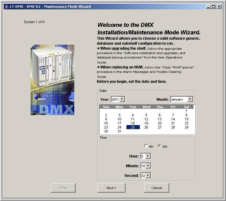 This screen picks up the time format preference from the WaveStar® CIT. You can provision the time format display for your WaveStar® CIT from the Network View by selecting View → Preferences and clicking on the Display tab. This screen allows you to choose your preference for time format, either a 12-hour clock or a 24-hour clock.
| ||||||||||||||||||||||||||||||||||
18 |
Important! The actual time and date are preset from your PC. On Screen 1 of 6 in the Maintenance Mode Wizard, read the information, verify the date and time, make any required changes, and click Next. Result: Screen 2 of 6 in the Maintenance Mode Wizard appears. 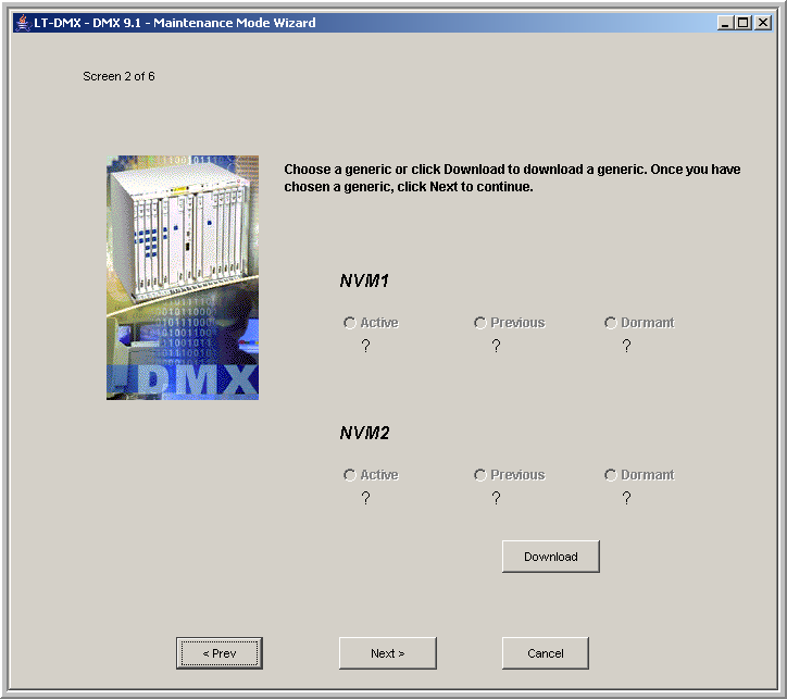 | ||||||||||||||||||||||||||||||||||
19 |
On Screen 2 of 6 in the Maintenance Mode Wizard, click Download. Result: Screen 1 of 3 in the Download Generic Wizard appears. 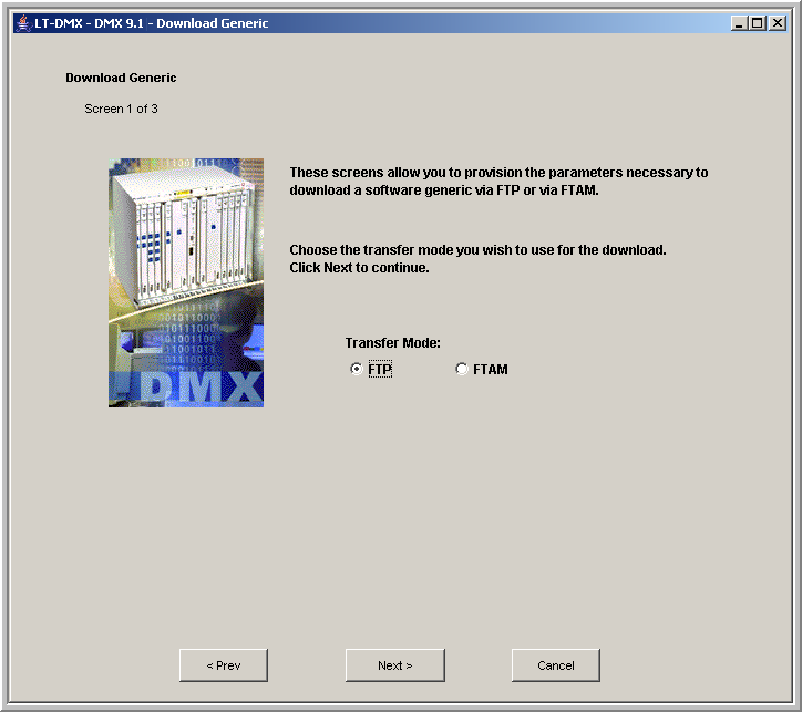 | ||||||||||||||||||||||||||||||||||
20 |
On Screen 1 of 3 in the Download Generic Wizard, read the information, select FTP and click Next. Result: Screen 2 of 3 in the Download Generic Wizard appears. 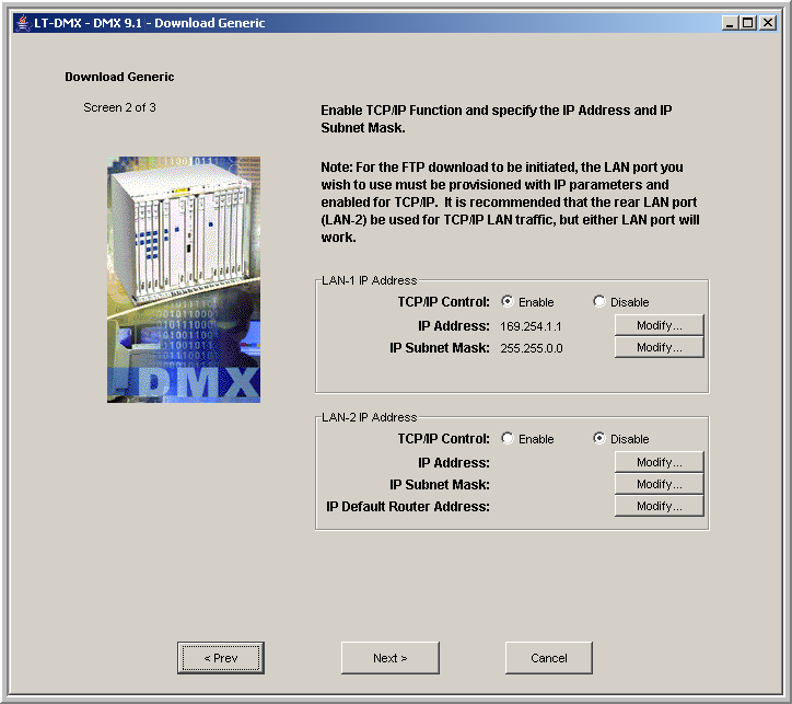 | ||||||||||||||||||||||||||||||||||
21 |
Important! LAN-1 is the LAN port on the faceplate of the LNW2 SYSCTL circuit pack. LAN-2 is the J16 IAO LAN port on the rear of the Alcatel-Lucent 1665 DMX shelf. If the boot code of your LNW2 ( Step 12) was 7.1 or later, you may see the IP Address and IP Subnet Mask field populated with the defaults illustrated in Screen 2 of 3. Important! If the default IP address and subnet mask are present, you must complete the initial software installation before you can change these values. If required, follow the instructions to enable TCP/IP Control on the LAN port to which you are connected. Click Modify to enter the IP Address, IP Subnet Mask, and/or IP Default Router Address. If you are connecting directly to the shelf without a router, the IP address of the FTP server must be in the same subnet as the LAN port. Click Next. Result: Screen 3 of 3 in the Download Generic Wizard appears. 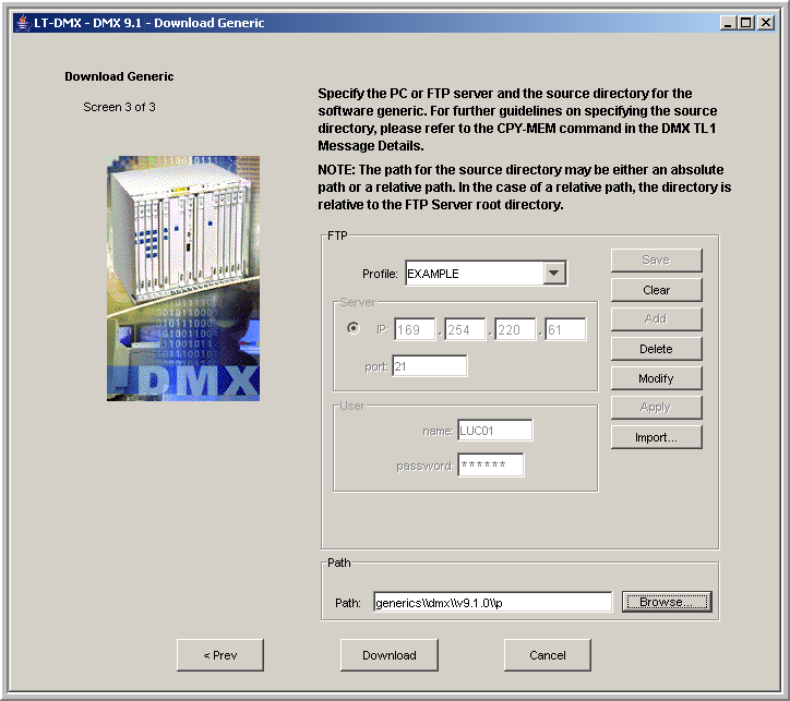 | ||||||||||||||||||||||||||||||||||
22 |
Select the connection from the Profile pull-down menu and proceed to Step 24. OR Enter information for a new profile as follows:
| ||||||||||||||||||||||||||||||||||
23 |
If you entered connection information in Step 22 and wish to keep the information for future FTP activities: Important! Entries to the Profile pull-down menu may be changed using the Modify, Apply, and Save buttons or removed using the Delete button. | ||||||||||||||||||||||||||||||||||
24 |
On Screen 3 of 3 in the Download Generic Wizard in the Path panel, enter the current location of the generic to be downloaded in the Path field or use the Browse button to select the generic to be downloaded. (If the FTP server is not the local host, the Browse button is greyed out.) Click Download. The value of the Path field can be either an absolute path or a relative path that is relative to the FTP server root directory. The absolute path must start with the drive name followed by a colon (:) then the path names; for example: C:\Program Files\Alcatel-Lucent\WaveStar CIT\generics\DMX\9.1.0\p. The syntax of the relative path must start with the path name; for example: \generics\DMX\9.1.0\p. If you had an older WaveStar® CIT installed prior to installing the current WaveStar® CIT, your path could start with C:\Program Files\Lucent Technologies\. If necessary, replace 9.1.0 with your current release, for example 9.1.1. If the FTP server is not the WaveStar® CIT, then enter the path starting at the FTP home directory on the server. Result: A warning message appears listing the options you provisioned in the previous screens. | ||||||||||||||||||||||||||||||||||
25 |
Verify the information and either click Yes to start the download process or click No to return to the download screen and change your selections. Result: If you choose yes, the following initial software download progress indicator runs for approximately 30 minutes. 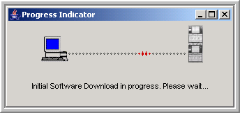 | ||||||||||||||||||||||||||||||||||
26 |
Do you wish to observe the FTP download progress?
| ||||||||||||||||||||||||||||||||||
27 |
Once the software generic download is complete, the following confirmation message appears. Click Yes to use the generic that is now in the Dormant area. 
Result: Screen 3 of 6 in the Maintenance Mode Wizard appears. 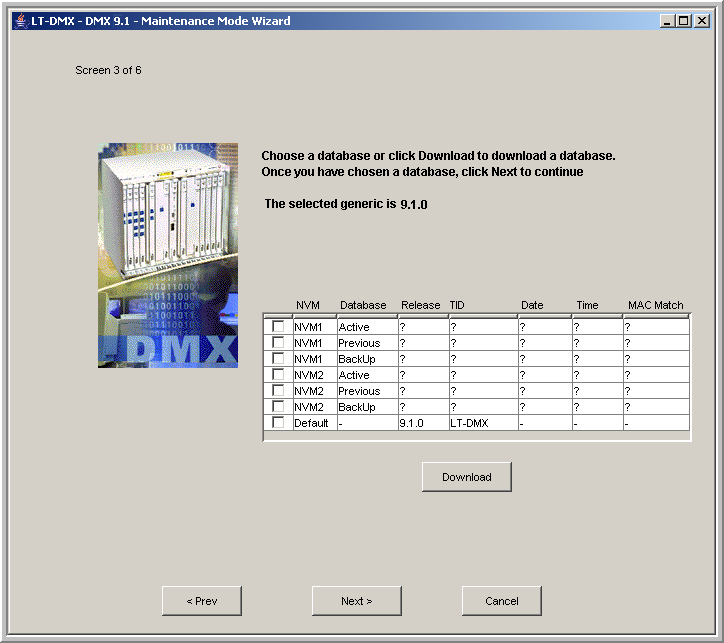 | ||||||||||||||||||||||||||||||||||
28 |
Important! Do NOT select the default database or you could loose service to your shelf. You MUST download your previously backed up database. On Screen 3 of 6 in the Maintenance Mode Wizard, click Download to select the database you backed up from your original SYSCTL. Result: Screen 1 of 3 in the Download Database Wizard appears. 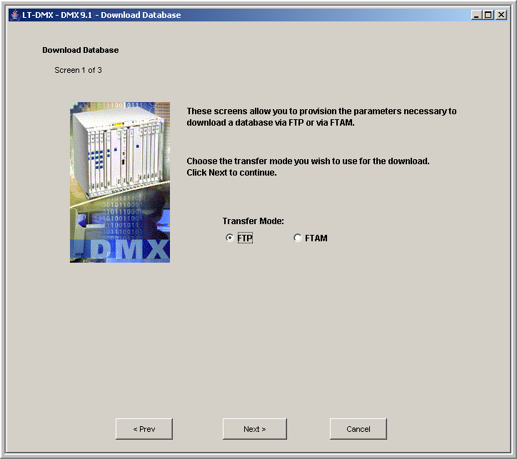 | ||||||||||||||||||||||||||||||||||
29 |
On Screen 1 of 3 in the Download Database Wizard, read the information, select FTP and click Next. Result: Screen 2 of 3 in the Download Database Wizard appears. 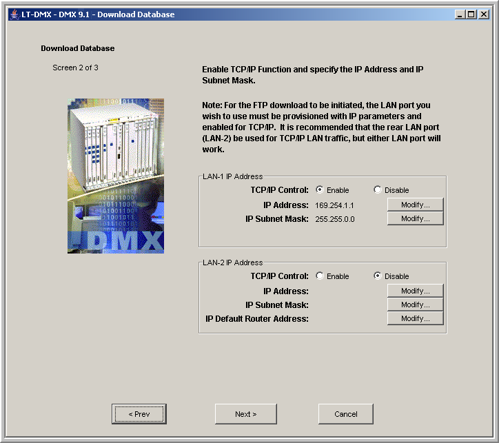 | ||||||||||||||||||||||||||||||||||
30 |
Important! LAN-1 is the LAN port on the faceplate of the LNW2 SYSCTL circuit pack. LAN-2 is the J16 IAO LAN port on the rear of the Alcatel-Lucent 1665 DMX shelf. On Screen 2 of 3 in the Download Database Wizard, the information entered in Step 21 should still be present and valid. If the information is not present, follow the instructions to enable TCP/IP Control on the LAN port to which you are connected. Click Modify to enter the IP Address, IP Subnet Mask, and/or IP Default Router Address. If you are connecting directly to the shelf without a router, the IP address of the FTP server must be in the same subnet as the LAN port. Click Next. Result: Screen 3 of 3 in the Download Database Wizard appears. 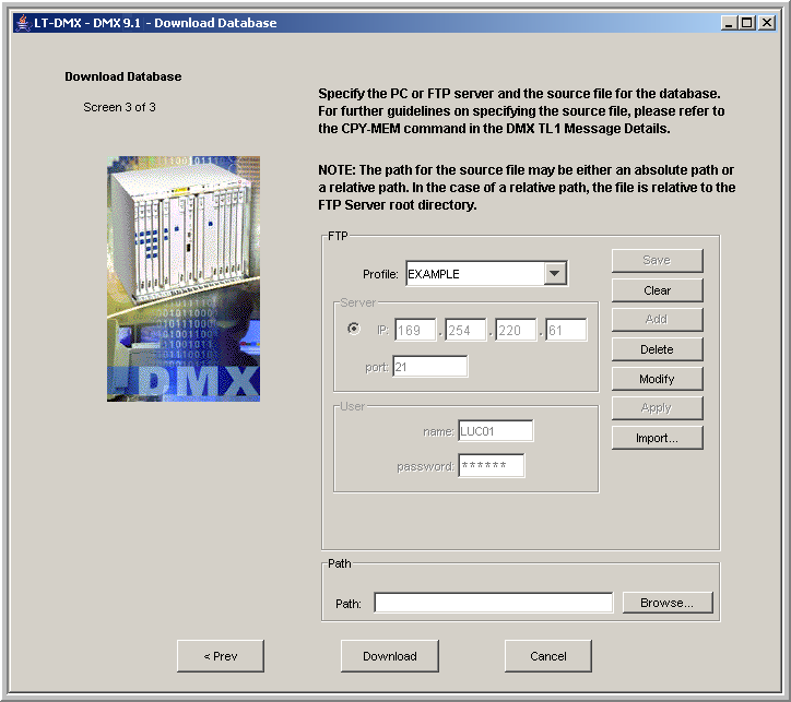 | ||||||||||||||||||||||||||||||||||
31 |
Select the connection from the Profile pull-down menu and proceed to Step 33. OR Enter information for a new profile as follows:
| ||||||||||||||||||||||||||||||||||
32 |
If you entered connection information in Step 31 and wish to keep the information for future FTP activities: Important! Entries to the Profile pull-down menu may be changed using the Modify, Apply, and Save buttons or removed using the Delete button. | ||||||||||||||||||||||||||||||||||
33 |
On Screen 3 of 3 in the Download Database Wizard in the Path panel, enter the location where the database information is stored. Enter the path and filename exactly as it was entered in Step 5. For example: \backups\<subdirectory>\<filename>. You may also click the Browse button next to the Path: field to browse to any directory on your PC and select the required file. Click Download. Important! The value of the Path field can be either an absolute path or a relative path that is relative to the FTP server root directory. The absolute path must start with the drive name followed by a colon (:) then the path names; for example: C:\temp\today\backup. The syntax of the relative path must start with the path name; for example: \temp\backup. The WaveStar® CIT directory automatically enters the relative path for the WaveStar® CIT. The default relative path is C:/Program Files/Alcatel-Lucent/WaveStar CIT/ If you had an older WaveStar® CIT installed prior to installing the current WaveStar® CIT, your path could start with C:\Program Files\Lucent Technologies\. Result: A warning message appears listing the options you provisioned in the previous screens. | ||||||||||||||||||||||||||||||||||
34 |
Verify the information and click Yes. Result: If you choose Yes, the database download progress indicator runs for approximately two minutes. 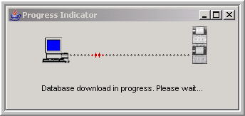 | ||||||||||||||||||||||||||||||||||
35 |
Do you wish to observe the FTP download progress?
| ||||||||||||||||||||||||||||||||||
36 |
Once the database download is complete, the following confirmation message appears. Click Yes to use the database that is now in the Backup area. 
Result: Screen 4 of 6 in the Maintenance Mode Wizard appears. In this screen, 9.1.0 is an example; your selected generic could be different, for example 9.1.1. 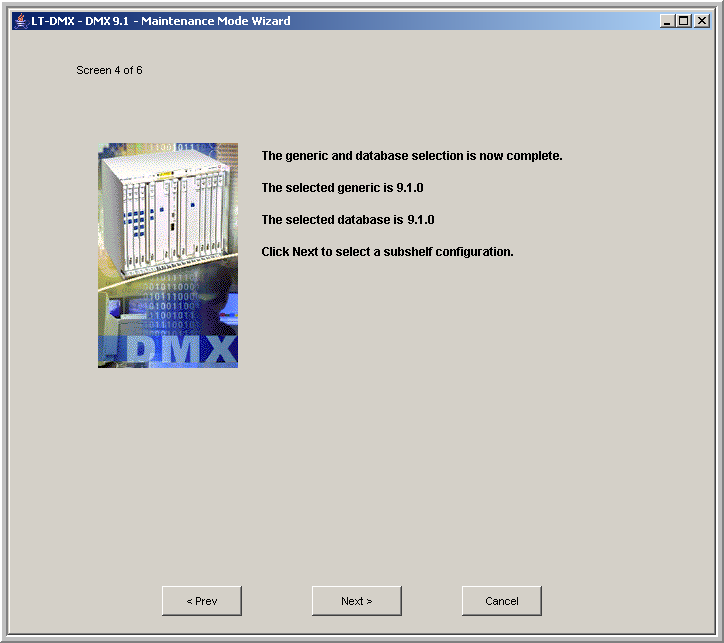 | ||||||||||||||||||||||||||||||||||
37 |
On Screen 4 of 6 in the Maintenance Mode Wizard, read the information, verify that you have selected the correct 9.1.x generic and the default database, and click Next . Result: Screen 5 of 6 in the Maintenance Mode Wizard appears. 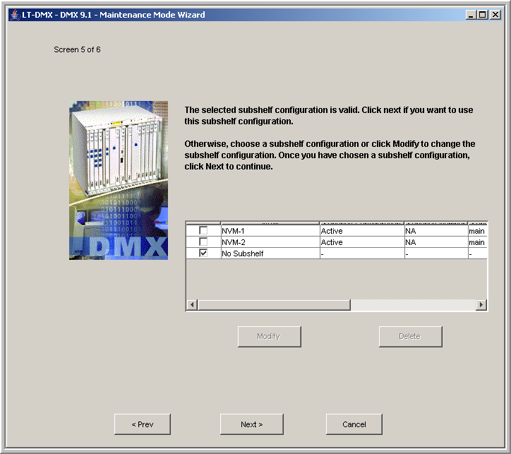 | ||||||||||||||||||||||||||||||||||
38 |
On Screen 5 of 6 in the Maintenance Mode Wizard, select No Subshelf or select NVM 1 or 2 if this shelf will be a subshelf and click Next . Result: Screen 6 of 6 in the Maintenance Mode Wizard appears. 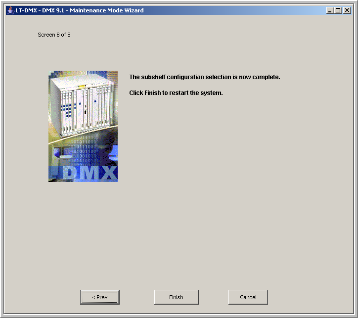 | ||||||||||||||||||||||||||||||||||
39 |
On Screen 6 of 6 in the Maintenance Mode Wizard, read the information, verify that you have selected the correct generic and database and click Finish to restart the system and apply the generic and database. Result: The Maintenance Mode Wizard closes and your connection to the shelf is terminated. The LNW2 SYSCTL exhibits the following visible cycles while the generic and database are installed and validated and the SYSCTL reboots:
| ||||||||||||||||||||||||||||||||||
40 |
To verify that the upgrade was successful, depress and hold the ACO TEST push-button on the LNW2 SYSCTL for about 4 seconds. Result: All LEDs on the shelf light. A red, 35-segment (5 x 7) rectangle appears in the IND display on the SYSCTL. Since the IND display is a 35-segment display, this test indicates all segments are working. | ||||||||||||||||||||||||||||||||||
41 |
Proceed to Procedure 12-16.4: Verify proper software generic. End of steps |