2-Fiber bidirectional line-switched ring (BLSR) switching
Introduction
The Alcatel-Lucent 1665 Data Multiplexer system performs 2-fiber bidirectional line-switched ring (BLSR) protection switching in response to automatically detected faults in OC-48 or OC-192 lines and external commands from the WaveStar® CIT or operations system (OS). For more information about Fault → Protection Switch, refer to the on-line help available from the WaveStar® CIT.
Ring definition
A ring is a collection of nodes that form a closed loop, where each node is connected to the adjacent nodes. BLSRs provide redundant bandwidth and/or equipment to ensure system integrity in the event of any transmission failure, including a fiber cut or node failure.
2-fiber OC-48 BLSR traffic capacity
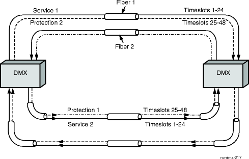
In a 2-fiber OC-48 BLSR, each bidirectional OC-48 line carries 24 STS-1 equivalent timeslots of service capacity (1–24) and 24 STS-1 equivalent timeslots of protection capacity (25–48).
Figure 4-1, Traffic capacity in an 2-fiber OC-48 BLSR illustrates the service and protection traffic capacities in a 2-fiber OC-48 BLSR.
Figure 4-1: Traffic capacity in an 2-fiber OC-48 BLSR

2-fiber OC-192 BLSR traffic capacity
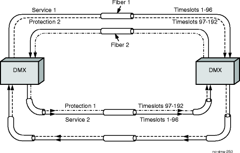
In a 2-fiber OC-192 BLSR, each bidirectional OC-192 line carries 96 STS-1 equivalent timeslots of service capacity (1–96) and 96 STS-1 equivalent timeslots of protection capacity (97–192).
Figure 4-2, Traffic capacity in an 2-fiber OC-192 BLSR illustrates the service and protection traffic capacities in a 2-fiber OC-192 BLSR.
Figure 4-2: Traffic capacity in an 2-fiber OC-192 BLSR

Switch request priorities
Important!
If a higher or equal priority switch request exists, a new switch request is denied.
The following table shows the 2-fiber BLSR protection switch priorities (in descending order of priority).
Table 4-30: Protection switching priorities (BLSR)
|
Switch Priorities (Descending Order) |
Source of Request |
|---|---|
|
Clear1 |
WaveStar® CIT or OS |
|
Lockout of Protection - Span |
WaveStar® CIT or OS |
|
Forced of Service to Protection, Ring |
WaveStar® CIT or OS |
|
Signal Fail - Ring |
Automatic |
|
Signal Degrade - Ring |
Automatic |
|
Manual Switch to Protection - Ring |
WaveStar® CIT or OS |
|
Wait to Restore |
Automatic |
|
Reverse Request - Ring |
Automatic |
|
No Request |
Automatic |
Notes:
The Clear request does not affect Signal Fail, Signal Degrade, Reverse Request, or No Request.
Bidirectional revertive protection switching
The optical line uses bidirectional revertive 2-fiber ring protection switching. Bidirectional refers to protection switching that is performed in the transmit and receive directions simultaneously. The traffic switches from the working tributaries of one line to the protection tributaries of the line in the opposite direction when a fault is detected. In revertive switching when the fault and wait-to-restore interval clear, the traffic switches back (reverts) to the working tributaries.
Self-healing rings
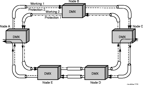
A 2-fiber BLSR is a self-healing (transport is automatically restored after node or fiber failures) ring configuration in which traffic is bidirectional between each pair of adjacent nodes and is protected by redundant bandwidth on the bidirectional lines that interconnect the nodes in the ring. Because traffic flow is bidirectional between the nodes, traffic can be added at one node and dropped at the next without traveling around the entire ring. This capability leaves the spans between other nodes available for additional traffic. Therefore, with distributed traffic patterns, a bidirectional line-switched ring can carry more traffic than the same facilities could carry if configured for a unidirectional path-switched ring. Additionally, you can use the protection capacity to provide unprotected transport for extra traffic when no failures are present. Up to 16 nodes are supported on a ring. Each OC-48 line carries 24 STS-1 equivalent timeslots of working capacity plus 24 STS-1 equivalent timeslots of protection capacity. Each OC-192 line carries 96 STS-1 equivalent timeslots of working capacity plus 96 STS-1 equivalent timeslots of protection capacity. In the event of a fiber or node failure, service is restored by switching traffic from the working capacity of the failed line to the protection capacity in the opposite direction around the ring. (See Figure 4-3, Normal traffic flow in a 2-fiber BLSR and Figure 4-4, Loopback protection switch in a 2-fiber BLSR.)
2-fiber BLSR traffic flow
The figure below shows normal (non-protection-switched) traffic flow on a 2-fiber BLSR.
Figure 4-3: Normal traffic flow in a 2-fiber BLSR

Protection switching
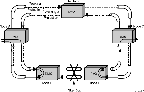
When a line failure triggers a protection switch, the nodes adjacent to the failure switch traffic on to protection capacity. Traffic heading toward the failure is looped back on to the protection capacity traveling away from the failure to reach its destination by traveling the opposite way around the ring (see the figure below). Service is reestablished on the protection capacity in less than 50 milliseconds after detection of the failure (for catastrophic failures in rings without existing protection switches or extra traffic).
Fiber cut example
Figure 4-4, Loopback protection switch in a 2-fiber BLSR illustrates a 2-fiber BLSR protection switch that results from a fiber cut.
Figure 4-4: Loopback protection switch in a 2-fiber BLSR

Protection traffic flow
For 2-fiber ring protection switching, the nodes adjacent to the failure make connections to bridge the add and through traffic to the protection tributaries of the line in the other direction. All drop and through traffic is selected from the protection tributaries of the line in the other direction.
In the figure above, traffic going from Node A to Node C that normally passes through Node E and Node D on "working 2" capacity is switched at Node E on to the "protection 2" capacity of the line leaving Node E in the direction of Node A. The traffic loops back through Nodes A, B, and C to Node D where it is looped back to Node C. Similarly, traffic going from Node C to Node A that normally passes through Node D and Node E on "working 1" capacity is switched at Node D on to the "protection 1" capacity of the line leaving Node D in the direction of Node C. The traffic loops back through Nodes C, B, and A to Node E where it is looped back to Node A. Note that only the nodes adjacent to the failure perform loopback protection switches. The same approach is used for a node failure. For example, if Node D fails, Nodes C and E perform loopback protection switches to provide an alternate route for ring traffic.
Extra traffic
Alcatel-Lucent 1665 DMX supports extra traffic on high-speed (main) 2-fiber OC-48 and in systems with OC-192 VLF mains, extra traffic is supported on OC-192 BLSRs in the mains and FNs. The extra traffic capability allows the protection channels to carry additional low-priority traffic during fault-free conditions.
The extra traffic is established by provisioning cross-connections to the high-speed (main) BLSR protection channels. Provisioning cross-connections on the protection channels is only supported on high-speed BLSRs. Pass through cross-connections are provisioned on the protection channels at intermediate nodes. (Protection channels that are not carrying Extra Traffic are terminated at the intermediate nodes.)
If a BLSR protection switch occurs, traffic is switched from the working channels to the protection channels and extra traffic is preempted.
If extra traffic circuits are preempted, AIS-P is used to squelch the circuits. When the BLSR protection switch clears, the extra traffic is restored.
NUT
Non-preemptible unprotected traffic is traffic carried on (working and/or protection) BLSR channels for which protection switching has been provisioned as disabled. As the name implies, NUT is unprotected and not preempted in the event of a protection switch.
BLSR protocols allow the available bandwidth of a BLSR to be partitioned into three types of channels:
Working traffic is protected against failure events via the BLSR APS protocol, while extra traffic is unprotected traffic carried on the protection channels. Any failure event that may require the protection channels for protection purposes shall preempt the extra traffic. NUT carried on non-preemptible unprotected channels affords a higher level of survivability as compared to extra traffic, which is preempted during a protection switch, but a lower level of survivability as compared to working traffic, which is carried on its corresponding protection channel during a protection switch. Note that non-preemptible unprotected traffic is not considered extra traffic.
Important!
Alcatel-Lucent 1665 DMX supports NUT on 2-fiber OC-48 and OC-192 BLSRs.