Unidirectional path-switched ring switching
Introduction
Alcatel-Lucent 1665 DMX supports path switched ring applications in accordance with the path protection switching schemes described in Telcordia Technologies GR-1400.
UPSR is the Alcatel-Lucent 1665 DMX default mode. Alcatel-Lucent 1665 DMX performs UPSR switching in response to automatically detected faults in paths and external commands from a WaveStar® CIT or operations system (OS). Alcatel-Lucent 1665 DMX supports UPSR switching for VT1.5 and STS-N signals on OC-N interfaces (OC-3/OC-12/OC-48/OC-192 OLIUs).
Path protection switching functions are available from the WaveStar® CIT System View menu when you select Fault → Protection Switch.
Protection switching priorities
The following table shows the UPSR protection switch priorities (in descending order of priority).
Table 4-31: Protection switch priorities (UPSR)
|
Switch Priorities (Descending Order) |
Source of Request |
|---|---|
|
Clear |
WaveStar® CIT or OS |
|
Lockout |
WaveStar® CIT or OS |
|
Forced |
WaveStar® CIT or OS |
|
Automatic Switch: Signal Failed |
Automatic |
|
Automatic Switch: Signal Degrade |
Automatic |
|
Manual |
WaveStar® CIT or OS |
Automatic path selector criteria
Alcatel-Lucent 1665 DMX performs automatic UPSR switching based on the automatic path selector criteria. The automatic path selector criteria uses the following hierarchy of signal impairments (ordered from top to bottom in increasing signal quality):
Important!
Alcatel-Lucent 1665 DMX selects the path-level signal with the best quality.
Unidirectional switching
Unidirectional switching refers to protection switching that is performed in the receive direction only. The transmitting terminal transmits the same path-level signal on two paths. The receiving terminal monitors the two path-level signals independently and chooses one path-level signal as the active path and the other path-level signal as the standby path. Alcatel-Lucent 1665 DMX selects the incoming path-level signal with the best quality (based on the automatic path selector criteria).
Nonrevertive switching
UPSR switching is nonrevertive. When a protection switch occurs, the receiving terminal selects the signal from the standby path. In nonrevertive switching, when the fault clears the receiving terminal does not switch back to the original path.
UPSR architecture
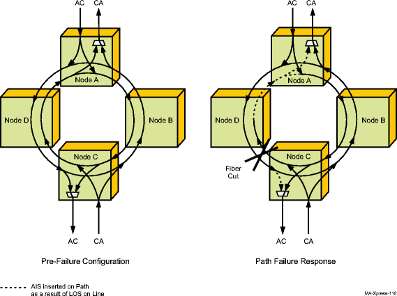
Figure 4-5, UPSR switching example illustrates an example of UPSR protection switching. The UPSR switching is performed in the receive direction. If the active incoming path-level signal fails, the circuit pack chooses the standby path-level signal. In the transmit direction, the circuit pack bridges the same path-level signal to the working and protection paths.
Figure 4-5: UPSR switching example

Path protection rings feed a SONET payload (STS-N or VT) from the ring entry point, simultaneously in both rotations of the ring, to the signal's ring drop or exit point as shown by traffic AC and CA. This duplication of the signal that enters the ring is called a "head-end bridge." The node that drops the signal from the ring monitors both ring rotations and is responsible for selecting the signal that has the highest quality based on LOS, LOF, path AIS, LOP, STS-N/VT unequipped, and STS-N/VT path BER performance. This function at the ring exit point is called a "tail-end switch."