Procedure 9-11.5: Create control plane network connections

- Overview

Use this procedure to create an end-to-end soft permanent connection (SPC) between the specified TNA end points.

A soft permanent connection is a user-to-user connection in which the user-to-network portion of the end-to-end connection is established by the network management system as a permanent connection, and the network portion of the end-to-end connection is established as a switched connection using the control plane. See Figure 9-18, Soft permanent connection (SPC) in a control plane network.

An end-to-end connection connecting edge ports consists of E-NNI connection segment(s) and I-NNI connection segment(s). E-NNI signaling is responsible for establishing the E-NNI portion of the end-to-end connection, as well as providing additional information that conveys the end-to-end request to the border nodes in the core for establishing the I-NNI portion of the end-to-end connection. In the control plane, the end-to-end points of an SPC are identified by Source and Destination TNAs, Source and Destination Logical Port IDs, and Source and Destination Subnetwork Point (SNP) IDs (called Source Labels [timeslot tributaries]). See Table 9-5, ENT-CONN parameters.

Steps

Complete the following steps to create a control plane network connection. Refer to Table 1.

 
1

From the System View menu, select Configuration → Create Control Plane Network Connections.


2

Enter the Service Attributes for the control plane connection.

Reference:

Table 9-5, ENT-CONN parameters


3

Select the Source TNA Address Type from the Source End Point attributes, then click Select.

Result:

The Tributary selection screen displays.


4

Expand the TNA address being used for the connection, select (highlight) the logical port. Click on the tributary, then click Select at the bottom of the screen.

Result:

The Source End Point attributes (Source TNA Address, Source Logical Port, and Source Label) are filled in.


5

Enter the parameters for the Destination End Point attributes, then click Apply. Read the warning message, then click Yes to execute the command.

Result:

Within a few seconds, a completion message is received.


6

Read the completion message, click OK, then click Cancel to exit.


7

From the System View menu, select View → Control Plane Network Connections to verify the connection.


End of steps

Control plane network connection parameters

Table 9-5, ENT-CONN parameters lists the provisionable parameters for a control plane network connection:

Table 9-5: ENT-CONN parameters

Parameter

Description

Service Parameters

callid

Call ID. Call Identifier is an operator-specific fixed-length 12-byte (24-character) hexadecimal string. One suggested format is where the first 4 bytes (8 characters) represent the source network element address (the hexadecimal encoding of the nodeid [ent-node]) and the remaining 8 bytes (16 characters) represent the local identifier.

protype

Protection Type.

Protection type specifies the protection type for the E-NNI segments of the SPC.

Value:

  • 0x1 — unprotected

  • 1+1 — protected

servlevel

Service Level is an integer in the range 0–255 that specifies the service level for the I-NNI segments of the SPC.

dir

Direction.

Direction specifies whether the connection is unidirectional or bidirectional.

Value:

  • 1WAY — unidirectional

  • 2WAY — bidirectional

bandwidth

Signal Rate specifies the signal rate of the connection.

Values:

  • STS1

  • STS3c

  • STS12c

  • STS48c

Source End Point Parameters

srctnatype

Source TNA Address Type. Source Transport Network Assigned Address (TNA) Type.

Values:

  • IPv4 — An IPv4 formatted Source TNA address consisting of four dot-separated integers ranging from 0 to 255, for example, 220.10.10.10.

  • IPv6 — An IPv6 formatted Source TNA address consisting of 8 dash-separated 4-digit hexadecimal numbers. For example, fedc-0000-0000-76b4-417a-1080-3210-1111.

  • NSAP — An NSAP formatted Source TNA address consisting of a 40-digit hexadecimal string. For example, 39840f8000000000000000000008006a067197aa.

srctnaaddress

Source TNA Address. Identifies an address assigned to one endpoint of the connection by the transport service provider. Srctnaaddress, in conjunction with srclogportid and srclabel, identifies the source of the connection.

See srctnatype for the allowable srctnaaddress values as a function of the srctnatype value.

srclogportid

Source Logical Port ID. An integer that identifies the source EDGE port (within the TNA). In conjunction with srctnaaddress and srclabel, it identifies the source of the connection.

Value is an integer in the range from 1 to 4294967295.

srclabel

Source Label. Source Label specifies a timeslot (tributary) on the source EDGE port identified by srclogportid. In conjunction with srctnaaddress and srclogportid, it identifies the source of the connection.

Source Label has a format of S-U-K-L-M, where: S specifies a particular STS-3 group within an STS-N, U specifies a particular STS-1 within an STS-3 group. K, L, and M are each 0.

Values:

  • S

    • 0 (port/line with a rate of STS1 or less)

    • 1 (1st STS-3c within an STS-N)

    • 2 (2st STS-3c within an STS-N)

      ...

    • N/3 (N/3th STS-3c within an OC-N port)

  • U

    • 0 (on port/line with a rate of STS1 or less, and when Signal Rate (bandwidth)=STS3c or greater)

    • 1 (1st STS-1 within an STS-3)

    • 2 (2nd STS-1 within an STS-3)

    • 3 (3rd STS-1 within an STS-3)

  • K=0

  • L=0

  • M=0

For example, for connecting the fourth STS-1 in an OC-48 EDGE port, srclabel=2-1-0-0-0.

For a connection to a VCG EDGE port, divide the VCG tributaries into groups of 3 (1–3, 4–6, 7–9,...) and apply the rules for OC-n ports.

Destination End Point Parameters

desttnatype

Destination TNA Address Type.. Destination Transport Network Assigned Address (TNA) Type.

See srctnatype for the format description.

desttnaaddress

Destination TNA Address. Destination Transport Network Assigned Address (TNA) identifies an address assigned to one endpoint of the connection by the transport service provider. desttnaaddress, in conjunction with destlogportid and destlabel, identifies the destination of the connection. See desttnatype for the allowable values as a function of the desttnatype value.

destlogportid

Destination Logical Port ID. Destination Logical Port ID is an integer that identifies the destination EDGE port (within the TNA). In conjunction with desttnaaddress and destlabel, it identifies the source of the connection.

Value is an integer in the range from 1 to 4294967295.

destlabel

Destination Label. Destination Label specifies a timeslot (tributary) on the destination EDGE port identified by destlogportid. In conjunction with desttnaaddress and destlogportid, it identifies the destination of the connection.

See srclabel for the format description.

Figure 9-18: Soft permanent connection (SPC) in a control plane network
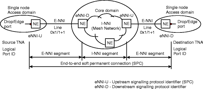
Soft permanent connection (SPC) in a control plane network

November 2011Copyright © 2011 Alcatel-Lucent. All rights reserved.