Procedure 11-19: Provision Q in Q stacked VLAN capability
 Overview
Use this procedure as a reference to provision the LAN/WAN Ethertype parameters (Tag Protocol Identifier [TPID] ) and port tags for stacked VLANs.
The examples in this procedure use a 3-node UPSR ring to illustrate the provisioning. It is assumed that the ring is properly provisioned for a multipoint (unswitched) Ethernet service using transparent (TRANS) mode at each of the Ethernet circuit packs. Prior provisioning includes provisioning the necessary multipoint (unswitched) cross-connections and setting up a virtual switch containing the LAN ports and VCG (WAN) ports being used.
In these examples, Node 1 is considered to be the customer interface node (ingress) and Node 3 is considered to be the network interface node that connects to a QinQ switch/router. Node 2 is configured to be a packet layer pass-through where the pass-through is performed by the switch, not at the SONET layer, in anticipation of service being added.
 Before you begin
Prior to performing this procedure, refer to Before you begin and Required equipment in this chapter and you must have complete work instructions for this procedure that detail:
Steps
Use the following examples for provisioning Ethertype and port tag parameters:
1 |
Use the WaveStar® CIT to log in to the Alcatel-Lucent 1665 DMXtend shelf. Reference: Procedure 14-2: Connect Personal Computer (PC) and establish WaveStar® CIT session |
2 |
Use the Configuration → Data → Create Port Tag from the System View menu to provision the port tags, if not already performed. Use the Configuration → Equipmentcommand, select the port, to provision the port parameters, including the Ethernet Type (in Hex) (TPID) value located under the Traffic Provisioning tab of the port parameters. Or, use the ed-eport/ed-vcg TL1 commands to provision the parameters in these examples. The Peak Information Rate (PIR) rate limiting feature on the LNW67/LNW68 circuit packs will not be effective in transparent mode if the Ethernet Type (ethertype) parameter for the LAN or WAN VCG ports is provisioned to any value other than FFFF or 8100. End of steps |
Example 1: Standard untagged frame
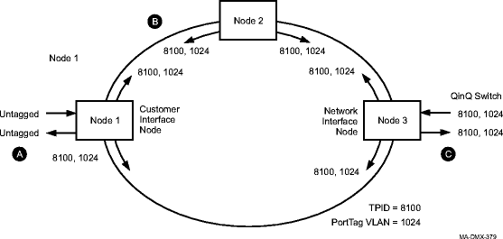
See Figure 11-30, Example 1 configuration for this example.
Figure 11-30: Example 1 configuration

This example assumes that:
-
The incoming traffic at Node 1 consists of "standard untagged frames" (no TPID value or TPID value other than FFFF or 8100).
-
Provisioning is performed as illustrated in the following table
Table 11-5: Provisioning for example 1
|
Node |
LAN (eport) |
WAN (vcg) | ||||
|---|---|---|---|---|---|---|
|
TPID |
dftporttag |
addporttag |
TPID |
dftporttag |
addporttag | |
|
Node 1 |
FFFF (8100 for LNW70/ LNW170) |
1024 |
8100 |
1024 | ||
|
Node 2 |
8100 |
1024 | ||||
|
Node 3 |
8100 |
1024 |
8100 |
1024 | ||
As a result of the provisioning illustrated in Figure 11-30, Example 1 configuration, and the prior assumptions, the following results are obtained:
-
A data stream of "standard tagged frames" with a TPID value of 8100, port tag VLAN value of 1024, and default priority value is assigned at Node 1 and transmitted out the LAN (eport) at Node 3.
-
The frame headers at the points labeled A, B, and C contain the following data:
Table 11-6: Expected results for frame headers in example 1
|
Points |
Destination Address |
Source Address |
VLAN TPID & Tag (Outer) |
VLAN TPID & Tag (Inner) |
... |
|---|---|---|---|---|---|
|
A |
C |
A |
NA (not applicable) |
NA |
|
|
B |
C |
A |
81 00 04 00 |
NA |
|
|
C |
C |
A |
81 00 04 00 |
NA |
Example 2: Standard VLAN tagged frames
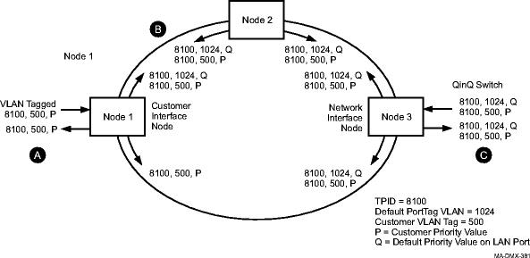
See Figure 11-31, Example 2 Configuration for this example.
Figure 11-31: Example 2 Configuration

This example assumes that:
-
The incoming traffic at Node 1 consists of "standard VLAN tagged frames" (TPID value 8100), VLAN port tag set to 500, and the priority set to a non-default value (P).
-
Provisioning is performed as illustrated in the following table.
Table 11-7: Provisioning for example 2
|
Node |
LAN (eport) |
WAN (vcg) | ||||
|
TPID |
dftporttag |
addporttag |
TPID |
dftporttag |
addporttag | |
|
Node 1 |
FFFF (8100 for LNW70/LNW170) |
1024 |
8100 |
1024 | ||
|
Node 2 |
8100 |
1024 | ||||
|
Node 3 |
8100 |
1024 |
8100 |
1024 | ||
As a result of the provisioning illustrated in Figure 11-31, Example 2 Configuration, and the prior assumptions, the following results are obtained:
-
A data stream of "double tagged frames" is transmitted out the eport on Node 3. The inner tag (8100, 500, and priority value [P]) are the ones provided by the end customer at Node 1. The outer tag (8100, 1024, and default priority value [Q] for LAN port) are assigned by Node 1.
-
The frame headers at the points labeled A, B, and C contain the following data:
Table 11-8: Expected results for frame headers in example 2
|
Points |
Destination Address |
Source Address |
VLAN TPID & Tag (Outer) |
VLAN TPID & Tag (Inner) |
... |
|
A |
C |
A |
NA |
81 00 01 F4 |
|
|
B |
C |
A |
81 00 04 00 |
81 00 01 F4 |
|
|
C |
C |
A |
81 00 04 00 |
81 00 01 F4 |