Procedure 9-8: Add IP route(s) through network
 Overview
Use this procedure to add IP Routes (IP Tunnels) through the data communications channel (DCC) OSI-based network.
 Privilege level
You must login as a Privileged user to complete this procedure.
IP routing examples
The following examples illustrate different methods of establishing IP routes through a network.
Each example is followed by the necessary instructions to program that example. In addition, tables are provided that list the required provisioning for the WaveStar® CIT, NEs, OMS, Router, and AnyMedia OS for each scenario.
Example 1: Local access over LAN
In this example, Figure 9-9, Local access over LAN, the PC-CIT is both the OS and FTP Server and is connected on the same subnet as GNE i.e. local access over the Local Area Network (LAN).
Figure 9-9: Local access over LAN
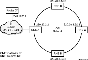
No manual route for the OS needs to be added in GNE as it would appear in GNE's routing table as a local entry.
ALL NEs are connected over a ring (over OSI-based DCC) and communicate using OSI, identifying each other through the NSAP addresses. They all support IP stack and thus have IP addresses and subnet masks assigned. Here, they are 1850 Product Family IP NEs but could also be connected to IP-only NEs (e.g. a case of IP Fringe discussed later).
How to Provision Example 1
Use the following information along with the Step instructions for this procedure to provision the route illustrated in Example 1:
|
At... |
Provision... |
|---|---|
|
PC-CIT |
Provision its own IP address (220.20.2.1) and subnet mask (24 or 255.255.255.0). Provision GNE with IP address 220.20.2.2 as default router |
|
GNE |
Provision its own IP address (220.20.2.2) and subnet mask (24 or 255.255.255.0) for the rear LAN port. Enable TCP/IP Function on the rear LAN port. No need to provision manual route to PC-CIT since GNE would advertise it as local entry within its own area. Ensure that TAP Advertise and TAP Learn are enabled. |
|
RNE B |
Provision its own IP address (220.20.3.1) and subnet mask (32 or 255.255.255.255) for DCC port. Enable TCP/IP Function on the DCC port. Enable Advertising of its own local entry. Ensure that TAP Advertise and TAP Learn are enabled. |
Use the following routing information at the PC-CIT to provision the route illustrated in Example 1:
|
Destination |
Gateway |
Interface |
Comments | |
|---|---|---|---|---|
|
PC-CIT |
||||
|
220.20.2.1/24 |
- |
lan |
populated by stack | |
|
default |
220.20.2.2 |
lan |
populated by stack |
Use the following routing information at the GNE/RNE to provision the route illustrated in Example 1:
|
Destination |
Next Hop Port |
Next Hop Address |
Owner |
TAP Advertisement |
Cost | |
|---|---|---|---|---|---|---|
|
GNE |
||||||
|
220.20.2.2/24 |
LAN |
- |
local |
no |
20 | |
|
220.20.2.1/24 |
LAN |
220.20.2.1 |
local |
yes |
20 | |
|
220.20.3.1/32 |
CLNP_TUNNEL |
<NSAP-B> |
TAP |
yes |
20 | |
|
220.20.3.2/32 |
CLNP_TUNNEL |
<NSAP-C> |
TAP |
yes |
20 | |
|
220.20.3.3/32 |
CLNP_TUNNEL |
<NSAP-D> |
TAP |
yes |
20 | |
|
RNE B |
||||||
|
220.20.3.1/32 |
LAN |
- |
local |
yes |
20 | |
|
220.20.2.1/24 |
CLNP_TUNNEL |
<NSAP-A> |
TAP |
yes |
20 | |
|
220.20.3.2/32 |
CLNP_TUNNEL |
<NSAP-C> |
TAP |
yes |
20 | |
|
220.20.3.3/32 |
CLNP_TUNNEL |
<NSAP-D> |
TAP |
yes |
20 |
Example 2: Access over IP WAN
In this example, Figure 9-10, Access over IP WAN, the GNE is accessed over the Internet Protocol Wide Area Network (IP WAN). The Optical Management System (OMS) (OMS) and the GNE are connected over a private internet/intranet via routers, R1 and R2.
Figure 9-10: Access over IP WAN
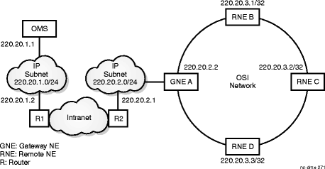
OMS and router R1 are on the same subnet 220.20.1.0/24 and router R2 and GNE are on another subnet 220.20.2.0/24. ALL NEs are connected over a ring (over OSI-based DCC) and communicate using OSI and identify each other through the NSAP addresses. Here, they are standalone IP NEs but could also be connected to IP-only NEs (e.g. a case of IP Fringe discussed later).
How to Provision Example 2
Use the following information along with the Step instructions for this procedure to provision the route illustrated in Example 2:
|
At ... |
Provision ... |
|---|---|
|
OMS |
Provision its own IP address (220.20.1.1) and subnet mask (24 or 255.255.255.0) Provision router, R1 with IP address 220.20.1.2 as default router |
|
Router R1 |
Provision IP addresses for its all interfaces - IP address (220.20.1.2) and subnet mask (24 or 255.255.255.0) - IP address for the interface connecting to intranet and the subnet mask of the directly attached subnet - If routers don't autoshare static routes, then Provision a static route to a subnet address which can cover maximum number of RNEs e.g. 220.20.3.0/24 as destination and GNE's IP address 220.20.2.2 as next-hop-address |
|
Router R2 |
Provision IP addresses for its all interfaces - IP address (220.20.2.1) and subnet mask (24 or 255.255.255.0) - IP address for the interface connecting to intranet and the subnet mask of the directly attached subnet Provision a static route to a subnet address which can cover maximum number of RNEs e.g. 220.20.3.0/24 as destination and GNE's IP address 220.20.2.2 as next-hop-address |
|
GNE |
Provision its own IP address (220.20.2.2) and subnet mask (24 or 255.255.255.0) for the rear LAN port. Enable TCP/IP Function on the rear LAN port. Provision R2 as default router with IP address 220.20.2.1 Provision manual route to OMS which it would advertise within its own OSI Level 1 area. The manual route would have OMS IP address 220.20.1.1/32 as destination and router R2's IP address 220.20.2.1 as next-hop-address. Ensure that TAP Advertise and TAP Learn are enabled. |
|
RNE B |
Provision its own IP address (220.20.3.1) and subnet mask (32 or 255.255.255.255) for DCC port. Enable TCP/IP Function on the DCC port. Enable Advertising of its own local entry. Ensure that TAP Advertise and TAP Learn are enabled. |
Use the following routing information at the OMS and Router to provision the route illustrated in Example 2:
|
Destination |
Gateway |
Interface |
Comments | |
|---|---|---|---|---|
|
OMS |
||||
|
220.20.1.1/24 |
- |
lan |
populated by stack | |
|
default |
220.20.1.2 |
lan |
populated by stack | |
|
Router |
||||
|
R1 |
220.20.1.2/24 |
- |
lan |
populated by stack |
|
220.20.3.0/24 |
220.20.2.2 |
lan |
1. populated by OSPF (if static routes autoshare) 2. manual (if static routes not autoshare e.g. in Cajun 550) | |
|
R2 |
220.20.2.1/24 |
- |
lan |
populated by stack |
|
220.20.3.0/24 |
220.20.2.2 |
lan |
manual |
Use the following routing information at the GNE/RNE to provision the route illustrated in Example 2:
|
Destination |
Next Hop Port |
Next Hop Address |
Owner |
TAP Advertisement |
Cost | |
|---|---|---|---|---|---|---|
|
GNE |
||||||
|
220.20.2.2/24 |
LAN |
- |
local |
no |
20 | |
|
default |
LAN |
220.20.2.1 |
local |
no |
20 | |
|
220.20.1.1/32 |
LAN |
220.20.2.1 |
manual |
yes |
20 | |
|
220.20.3.1/32 |
CLNP_TUNNEL |
<NSAP-B> |
TAP |
yes |
20 | |
|
220.20.3.2/32 |
CLNP_TUNNEL |
<NSAP-C> |
TAP |
yes |
20 | |
|
220.20.3.3/32 |
CLNP_TUNNEL |
<NSAP-D> |
TAP |
yes |
20 | |
|
RNE B |
||||||
|
220.20.3.1/32 |
LAN |
- |
local |
yes |
20 | |
|
220.20.1.1/32 |
CLNP_TUNNEL |
<NSAP-A> |
TAP |
yes |
20 | |
|
220.20.3.2/32 |
CLNP_TUNNEL |
<NSAP-C> |
TAP |
yes |
20 | |
|
220.20.3.3/32 |
CLNP_TUNNEL |
<NSAP-D> |
TAP |
yes |
20 |
Example 3: Multi-Area operations
In this example, Figure 9-11, Multi-Area operations, an extension to Example 2, we have added other NEs that are deployed in different areas (1, 2, and 3). RNE C, P, and X are level-2 routers which enable communications across areas. But the manual route to OMS provisioned at GNE wouldn't be advertised by RNE C to other areas. This requires establishing manual route across areas which are then advertised by Level 2 routers within their areas. Each area can be represented by a single subnet. This also requires adding static entries to each subnet in Router R2.
Figure 9-11: Multi-Area operations
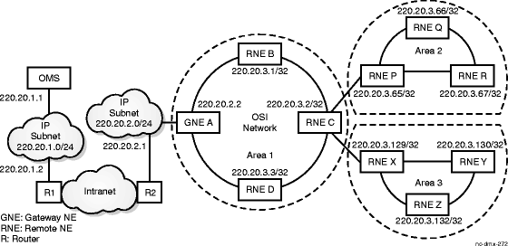
Careful planning and design of subnet addresses for these areas could reduce the number of static entries required at Router R2.
How to Provision Example 3
Use the following information along with the Step instructions for this procedure to provision the route illustrated in Example 3:
|
At ... |
Provision ... |
|---|---|
|
OMS |
Provision its own IP address (220.20.1.1) and subnet mask (24 or 255.255.255.0) Provision router, R1 with IP address 220.20.1.2 as default router |
|
Router R1 |
Provision IP addresses for its all interfaces - IP address (220.20.1.2) and subnet mask (24 or 255.255.255.0) - IP address for the interface connecting to intranet and the subnet mask of the directly attached subnet - If routers don't autoshare static routes, then Provision a static route to a subnet address which can cover maximum number of RNEs e.g. 220.20.3.0/24 as destination covers subnets 220.20.3.0/26, 220.20.3.64/26 and 220.20.3.128/26. The GNE's IP address 220.20.2.2 as next-hop-address. |
|
Router R2 |
Provision IP addresses for its all interfaces - IP address (220.20.2.1) and subnet mask (24 or 255.255.255.0) - IP address for the interface connecting to intranet and the subnet mask of the directly attached subnet Provision a static route to a subnet address which can cover maximum number of RNEs e.g. 220.20.3.0/24 as destination covers subnets 220.20.3.0/26, 220.20.3.64/26 and 220.20.3.128/26. The GNE's IP address 220.20.2.2 as next-hop-address. |
|
GNE |
Provision its own IP address (220.20.2.2) and subnet mask (24 or 255.255.255.0) for the rear LAN port. Enable TCP/IP Function on the rear LAN port. Provision R2 as default router with IP address 220.20.2.1 Provision manual route to OMS which it would advertise within its own area. The manual route would have OMS IP address 220.20.1.1/32 as destination and router R2's IP address 220.20.2.1 as next-hop-address. Ensure that TAP Advertise and TAP Learn are enabled. Provision manual route for two areas with RNE P's and RNE X's IP addresses (220.20.3.65/26 and 220.20.3.129/26) as destination and their respective NSAP addresses as the next hop address. No need to advertise this entry. (In case, any area can't be covered with one subnet, more than one route might have to be added) |
|
RNE C |
Provision its own IP address (220.20.3.2) and subnet mask (32 or 255.255.255.255) for DCC port. Enable TCP/IP Function on the DCC port. Enable Advertising of its own local entry. Ensure that TAP Advertise and TAP Learn are enabled. |
|
RNE P |
Provision its own IP address (220.20.3.65) and subnet mask (32 or 255.255.255.255) for DCC port. Enable TCP/IP Function on the DCC port. Enable Advertising of its own local entry. Ensure that TAP Advertise and TAP Learn are enabled. Provision manual route to GNE which it would advertise within its own area. The manual route would have OMS IP address 220.20.1.1/32 as destination and GNE's NSAP address as the next-hop address. Set advertise enable for this entry. |
|
RNE X |
Provision its own IP address (220.20.3.129) and subnet mask (32 or 255.255.255.255) for DCC port. Enable TCP/IP Function on the DCC port. Enable Advertising of its own local entry. Ensure that TAP Advertise and TAP Learn are enabled. Provision manual route to GNE which it would advertise within its own area. The manual route would have OMS IP address 220.20.1.1/32 as destination and GNE's NSAP address as the next-hop address. Set advertise enable for this entry. |
|
RNE R |
Provision its own IP address (220.20.3.67) and subnet mask (32 or 255.255.255.255) for DCC port. Enable TCP/IP Function on the DCC port. Enable Advertising of its own local entry. Ensure that TAP Advertise and TAP Learn are enabled. |
Use the following routing information at the OMS and NE (GNE/RNE) to provision the route illustrated in Example 3:
|
Destination |
Gateway |
Interface |
Comments | |
|---|---|---|---|---|
|
OMS |
||||
|
220.20.1.1/24 |
- |
lan |
populated by stack | |
|
default |
220.20.1.2 |
lan |
populated by stack | |
|
Router |
||||
|
R1 |
220.20.1.2/24 |
- |
lan |
populated by stack |
|
220.20.3.0/24 |
220.20.2.2 |
lan |
1. populated by OSPF (if static routes autoshare) 2. manual (if static routes not autoshare e.g. in Cajun 550) | |
|
R2 |
220.20.2.1/24 |
- |
lan |
populated by stack |
|
220.20.3.0/24 |
220.20.2.2 |
lan |
manual |
Use the following routing information at the GNE/RNE to provision the route illustrated in Example 3:
|
Destination |
Next Hop Port |
Next Hop Address |
Owner |
TAP Advertisement |
Cost | |
|---|---|---|---|---|---|---|
|
GNE |
||||||
|
220.20.2.2/24 |
LAN |
- |
local |
no |
20 | |
|
default |
LAN |
220.20.2.1 |
local |
no |
20 | |
|
220.20.1.1/32 |
LAN |
220.20.2.1 |
manual |
yes |
20 | |
|
220.20.3.65/26 |
CLNP_TUNNEL |
<NSAP-P> |
manual |
no |
20 | |
|
220.20.3.129/26 |
CLNP_TUNNEL |
<NSAP-X> |
manual |
no |
20 | |
|
220.20.3.1/32 |
CLNP_TUNNEL |
<NSAP-B> |
TAP |
yes |
20 | |
|
220.20.3.2/32 |
CLNP_TUNNEL |
<NSAP-C> |
TAP |
yes |
20 | |
|
220.20.3.3/32 |
CLNP_TUNNEL |
<NSAP-D> |
TAP |
yes |
20 | |
|
RNE C |
||||||
|
220.20.3.2/32 |
LAN |
- |
local |
yes |
20 | |
|
220.20.1.1/32 |
CLNP_TUNNEL |
<NSAP-A> |
TAP |
yes |
20 | |
|
220.20.3.1/32 |
CLNP_TUNNEL |
<NSAP-B> |
TAP |
yes |
20 | |
|
220.20.3.3/32 |
CLNP_TUNNEL |
<NSAP-D> |
TAP |
yes |
20 | |
|
RNE P |
||||||
|
220.20.3.65/32 |
LAN |
- |
local |
yes |
20 | |
|
220.20.1.1/32 |
CLNP_TUNNEL |
<NSAP-A> |
manual |
yes |
20 | |
|
220.20.3.66/32 |
CLNP_TUNNEL |
<NSAP-Q> |
TAP |
yes |
20 | |
|
220.20.3.67/32 |
CLNP_TUNNEL |
<NSAP-R> |
TAP |
yes |
20 | |
|
RNE X |
||||||
|
220.20.3.129/32 |
LAN |
- |
local |
yes |
20 | |
|
220.20.1.1/32 |
CLNP_TUNNEL |
<NSAP-A> |
manual |
yes |
20 | |
|
220.20.3.130/32 |
CLNP_TUNNEL |
<NSAP-Y> |
TAP |
yes |
20 | |
|
220.20.3.131/32 |
CLNP_TUNNEL |
<NSAP-Z> |
TAP |
yes |
20 | |
|
RNE R |
||||||
|
220.20.3.67/32 |
LAN |
- |
local |
yes |
20 | |
|
220.20.1.1/32 |
CLNP_TUNNEL |
<NSAP-A> |
TAP |
yes |
20 | |
|
220.20.3.65/32 |
CLNP_TUNNEL |
<NSAP-P> |
TAP |
yes |
20 | |
|
220.20.3.66/32 |
CLNP_TUNNEL |
<NSAP-Q> |
TAP |
yes |
20 |
Example 4: IP NEs on the fringe
In this example, Figure 9-12, IP NEs on the fringe, another extension of Example 2, IP Routing is used to reach the IP-only NEs on the fringe of the OSI network, allowing termination of an IP connection at the IP-only host connected to RNE C on the same IP subnet. It can also be reached via additional routers).
Figure 9-12: IP NEs on the fringe
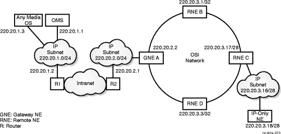
The RNE C is connected via its LAN port and is given a real IP address 220.20.3.17 (rather 220.20.3.2) which belongs to the subnet 220.20.3.16/28. The RNE C is still reachable via the IP address 220.20.3.0/24 provisioned at Router R1 as destination for the entire OSI subnet.
This also requires manual provisioning of the route to AnyMedia OS at the GNE and RNE C being provisioned as default router at the IP-only NE.
How to Provision Example 4
Use the following information along with the Step instructions for this procedure to provision the route illustrated in Example 4:
|
At ... |
Provision ... |
|---|---|
|
OMS |
Provision its own IP address (220.20.1.1) and subnet mask (24 or 255.255.255.0) Provision router, R1 with IP address 220.20.1.2 as default router |
|
AnyMedia OS |
Provision its own IP address (220.20.1.3) and subnet mask (24 or 255.255.255.0) Provision router, R1 with IP address 220.20.1.2 as default router |
|
Router R1 |
Provision IP addresses for its all interfaces - IP address (220.20.1.2) and subnet mask (24 or 255.255.255.0) - IP address for the interface connecting to intranet and the subnet mask of the directly attached subnet - If routers don't autoshare static routes, then Provision a static route to a subnet address which can cover maximum number of RNEs e.g. 220.20.3.0/24 as destination and GNE's IP address 220.20.2.2 as next-hop-address. |
|
Router R2 |
Provision IP addresses for its all interfaces - IP address (220.20.2.1) and subnet mask (24 or 255.255.255.0) - IP address for the interface connecting to intranet and the subnet mask of the directly attached subnet Provision a static route to a subnet address which can cover maximum number of RNEs e.g. 220.20.3.0/24 as destination and GNE's IP address 220.20.2.2 as next-hop-address. |
|
GNE |
Provision its own IP address (220.20.2.2) and subnet mask (24 or 255.255.255.0) for the rear LAN port. Enable TCP/IP Function on the rear LAN port. Provision R2 as default router with IP address 220.20.2.1 Provision manual route to OMS which it would advertise within its own area. The manual route would have OMS IP address 220.20.1.1/32 as destination and router R2's IP address 220.20.2.1 as next-hop-address Ensure that TAP Advertise and TAP Learn are enabled. Provision a manual route to AnyMedia OS similar to OMS and IP address of AnyMedia OS, 220.20.1.3/24 |
|
RNE C |
Provision its own IP address (220.20.3.17) and subnet mask (28 or 255.255.255.240) for the LAN port. Enable TCP/IP Function on the LAN port. Enable Advertising of its own local entry. Ensure that TAP Advertise and TAP Learn are enabled. |
|
IP-only NE |
Provision its own IP address (220.20.3.18) and subnet mask (28 or 255.255.255.240) Provision RNE C as its default router with IP address (220.20.3.17) |
Use the following routing information at the OMS and Router to provision the route illustrated in Example 4:
|
Destination |
Gateway |
Interface |
Comments | |
|---|---|---|---|---|
|
OMS |
||||
|
220.20.1.1/24 |
- |
lan |
populated by stack | |
|
default |
220.20.1.2 |
lan |
populated by stack | |
|
Router |
||||
|
R1 |
220.20.1.2/24 |
- |
lan |
populated by stack |
|
220.20.3.0/24 |
220.20.2.2 |
lan |
1. populated by OSPF (if static routes autoshare) 2. manual (if static routes not autoshare e.g. in Cajun 550) | |
|
R2 |
220.20.2.1/24 |
- |
lan |
populated by stack |
|
220.20.3.0/24 |
220.20.2.2 |
lan |
manual |
Use the following routing information at the AnyMedia OS to provision the route illustrated in Example 4:
|
Destination |
Gateway |
Interface |
Comments | |
|---|---|---|---|---|
|
AnyMedia OS |
||||
|
220.20.1.3/24 |
- |
lan |
populated by stack | |
|
default |
220.20.1.2 |
lan |
populated by stack |
Use the following routing information at the GNE/RNE to provision the route illustrated in Example 4:
|
Destination |
Next Hop Port |
Next Hop Address |
Owner |
TAP Advertisement |
Cost | |
|---|---|---|---|---|---|---|
|
GNE |
||||||
|
220.20.2.2/24 |
LAN |
- |
local |
no |
20 | |
|
default |
LAN |
220.20.2.1 |
local |
no |
20 | |
|
220.20.1.1/32 |
LAN |
220.20.2.1 |
manual |
yes |
20 | |
|
220.20.1.3/32 |
LAN |
220.20.2.1 |
manual |
yes |
20 | |
|
220.20.3.1/32 |
CLNP_TUNNEL |
<NSAP-B> |
TAP |
yes |
20 | |
|
220.20.3.2/32 |
CLNP_TUNNEL |
<NSAP-C> |
TAP |
yes |
20 | |
|
220.20.3.3/32 |
CLNP_TUNNEL |
<NSAP-D> |
TAP |
yes |
20 | |
|
RNE C |
||||||
|
220.20.3.17/28 |
LAN |
- |
local |
yes |
20 | |
|
220.20.3.18/28 |
LAN |
- |
local |
no |
20 | |
|
220.20.1.1/32 |
CLNP_TUNNEL |
<NSAP-A> |
TAP |
yes |
20 | |
|
220.20.3.1/32 |
CLNP_TUNNEL |
<NSAP-B> |
TAP |
yes |
20 | |
|
220.20.3.3/32 |
CLNP_TUNNEL |
<NSAP-D> |
TAP |
yes |
20 |
Use the following routing information at the IP-Only NE to provision the route illustrated in Example 4:
|
Destination |
Gateway |
Interface |
Comments | |
|---|---|---|---|---|
|
IP-Only NE |
||||
|
220.20.3.18/28 |
- |
lan |
populated by stack | |
|
default |
220.20.3.17 |
lan |
populated by stack |
Example 5: Multiple GNEs scenario
In this example, Figure 9-13, Multiple GNEs scenario, a single area has many NEs and if IP Routing is provisioned, the Tunnel Auto Provisioning (TAP) advertisement that would be exchanged would be significantly high and lot of such traffic would pass through GNE.
Figure 9-13: Multiple GNEs scenario
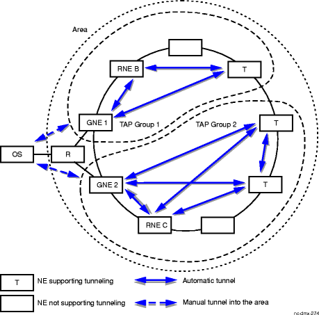
To avoid the overloading on the network and particularly on GNE, TAP Groups are defined. With this, TAP enabled NEs wouldn't listen to the advertisements from NEs outside their TAP groups and thus don't form tunnels with them or through them.
Setting up TAP groups necessitates two GNEs, each with one manual route entry to OS and advertise in their respective TAP groups.
How to Provision Example 5
Use the following information along with the Step instructions for this procedure to provision the route illustrated in Example 5:
|
At ... |
Provision ... |
|---|---|
|
OS |
Provision its own IP address and subnet mask . Provision router as default router. |
|
Router |
Provision IP addresses for all interfaces. Provision 2 static routes (one to GNE 1 and one to GNE 2). |
|
GNE 1 |
Provision its own IP address and subnet mask for the rear LAN port. Enable TCP/IP Function on the rear LAN port. Provision default router . Provision manual route entry to OS with TAP Group 1. Ensure that TAP Advertise and TAP Learn are enabled. |
|
GNE 2 |
Provision its own IP address and subnet mask for the rear LAN port. Enable TCP/IP Function on the rear LAN port. Provision default router . Provision manual route entry to OS with TAP Group 2. Ensure that TAP Advertise and TAP Learn are enabled. |
|
RNE B |
Provision its own IP address and subnet mask for DCC port. Enable TCP/IP Function on the DCC port. Enable Advertising of its own local entry. Ensure that TAP Advertise and TAP Learn are enabled for TAP Group 1. |
|
RNE C |
Provision its own IP address and subnet mask for DCC port. Enable TCP/IP Function on the DCC port. Enable Advertising of its own local entry. Ensure that TAP Advertise and TAP Learn are enabled for TAP Group 2. |
 Before you begin
Prior to performing this procedure,
-
Refer to Before you begin and Required equipment in this chapter.
-
Verify that the work instructions identify the OS/FTP server, gateway network element, and remote network element.
-
Verify that the work instructions specify the required provisioning at each network element (for example, IP addresses and subnet masks).
-
If the FTP server is a local PC (WaveStar® CIT), verify that the PC's IP address and Subnet Mask parameters are provisioned and that a static route on the PC connects it to the remote NEs.
-
If the FTP server is a remote OS, verify that the remote OS' IP address and Subnet Mask parameters are provisioned and if the remote OS and GNE are in different subnetworks, verify that the Default Router IP address is provisioned.
Steps
Complete the following steps to add IP routes through the data communications channel (DCC) OSI-based network:
1 |
If the remote OS is a local PC, a static route on the PC must provide a path to the remote NEs. If packets are intended for the remote NE, then you must route to the gateway NE. If the remote OS is a remote operations system, the static route must be entered on the router. Example: If the OS is a local PC, from the MS-DOS prompt, enter route add 120.20.20.0 MASK 255.255.255.0 120.20.30.1. In this example 120.20.20.0 is the subnetwork address of the remote NE and 120.20.30.1 is the IP address of the gateway NE. The Subnet Mask of the OS and the Gateway is 255.255.255.0 while the Subnet Mask of the Remote NEs is 255.255.255.255. |
2 |
If the remote OS and GNE are in different subnetworks, verify that the router in each subnetwork has IP addresses provisioned for all interfaces and that the static route, as described in Step 1, has been provisioned on the router. |
3 |
Establish a login session to the GNE. Reference: Procedure 14-2: Connect Personal Computer (PC) and establish WaveStar® CIT session |
4 |
At the GNE:
Important! If automatic synchronization is unsuccessful, the date and time must be reset manually. Reference: Procedure 7-10: Set date and time. |
5 |
Re-establish the log in session to the GNE. Reference: Procedure 14-2: Connect Personal Computer (PC) and establish WaveStar® CIT session |
6 |
At the GNE:
|
7 |
Log out of the GNE and log in to the remote NE. Reference: Procedure 14-2: Connect Personal Computer (PC) and establish WaveStar® CIT session |
8 |
At the RNE:
Important! If automatic synchronization is unsuccessful, the date and time must be reset manually. Reference: Procedure 7-10: Set date and time. |
9 |
Re-establish the log in session to the RNE. Reference: Procedure 14-2: Connect Personal Computer (PC) and establish WaveStar® CIT session |
10 |
At the RNE:
|
11 |
If required, repeat Step 7 through Step 10 at other RNEs. End of steps |