Procedure 11-16: Create preferred spanning tree configuration
 Overview
This procedure provides an example to determine (and create) your preferred spanning tree configuration.
Important!
Networks running 802.1d STP support a maximum of up to nine nodes participating in a spanning tree. Networks with more than nine nodes will not reconfigure properly. Spanning tree default parameters support a network of up to nine nodes.
Networks running 802.1w rapid spanning tree protocol support more than nine nodes participating in a spanning tree. To support more than nine nodes in the spanning tree, the maximum age timer must be increased. Note that spanning tree restoration time increases as the number of nodes increase.
If the network consists of more than nine (9) nodes which are participating in the spanning tree configuration, use the following formula to determine the proper setting for the spanning tree maximum age timer (stmaxage): 2N + 6, where N equals the number of nodes.
For example, if the network consists of 16 nodes, then the stmaxage timer should be set to 38 seconds: 2 x (16) + 6 = 38.
 Before you begin
Prior to performing this procedure:
-
Refer to Before you begin and Required equipment in this chapter.
-
Know which nodes in the network are participating in the spanning tree configuration for the service being configured
-
Have a knowledge of Ethernet services and spanning tree configurations
Steps
Use the following procedure as an example for determining the preferred spanning tree configuration.
1 |
Use the WaveStar® CIT to log in to a terminating Alcatel-Lucent 1665 DMXtend shelf. Reference: Procedure 14-2: Connect Personal Computer (PC) and establish WaveStar® CIT session | ||||||
2 |
On the System View menu at each node, select Administration → OSI Neighbor Map to retrieve a node-to-node listing of every node in the network. Important! If a drawing of the network is not provided with the work instructions, it is recommended that you draw a simple diagram of the ring (indicating node-to-node connections) and list each node's TID. Result: The OSI Neighbor Map window opens. | ||||||
3 |
Verify that the system configuration is the same as specified on your work instructions. | ||||||
4 |
From your work instructions and the network map, determine the nodes in the ring at which Ethernet services are provided and are part of the same spanning tree group. Important! When determining if the ring consists of an odd or even number of nodes, count only the nodes at which Ethernet service is being provided in the same spanning tree configuration. If a node in the ring has only SONET pass through cross-connections for Ethernet services, that node is not counted in determining an odd or even configuration. The figures in this procedure assume all nodes are providing Ethernet service. | ||||||
5 |
Determine if the ring consists of an odd or even number of nodes.
| ||||||
6 |
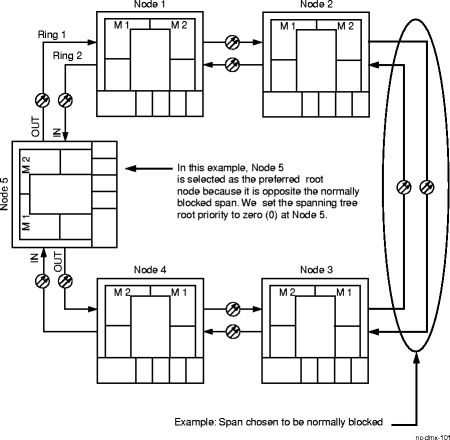
Refer to Figure 11-26, Spanning tree odd node example for rings with an odd number of nodes. Figure 11-26: Spanning tree odd node example | ||||||
7 |
Select the span that should be blocked under nominal conditions. The span should be selected based on traffic patterns to get the most efficient use of capacity on both sides of the ring during nominal conditions. Example The span between Nodes 2 and 3 was selected in this example. | ||||||
8 |
Determine the preferred root node. The preferred root node in an odd-number node ring is the node on the ring opposite the span which should be normally blocked. Example In the odd node configuration figure above, Node 5 is the preferred root node. | ||||||
9 |
Use the WaveStar® CIT to log in to the preferred root node. | ||||||
10 |
From the System View menu, select Configuration → Data → Create Spanning Tree Group or use the ent-stgrp TL1 command. Result: The Create Spanning Tree Group window opens displaying the parameters for the spanning tree group. | ||||||
11 |
Set the spanning tree Root Priority parameter (strp) to zero (0) at the preferred root node (Node 5 in this example). At ALL other Ethernet nodes in the ring, set the spanning tree root priority to the default value of 32768. END OF STEPS FOR ODD NODE EXAMPLE | ||||||
12 |
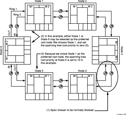
Refer to Figure 11-27, Spanning tree even node example for rings with an EVEN number of nodes: Figure 11-27: Spanning tree even node example | ||||||
13 |
Select the span that should be blocked under nominal conditions. The span should be selected based on traffic patterns to get the most efficient use of capacity on both sides of the ring during nominal conditions. Example The span between Nodes 3 and 4 was selected in this example. | ||||||
14 |
Determine the preferred root node. The preferred root node in an even-number node ring may be either of the two nodes at the opposite ends of the span that is opposite to the span which is normally blocked. Example In the even node configuration figure above, either Node 1 or Node 6 may be selected as the preferred root node. Note that there are 2 spans between Node 3 and Node 1, and two spans between Node 4 and Node 6. In this example, we choose Node 1 to be the preferred root node. | ||||||
15 |
Use the WaveStar® CIT to log in to the preferred root node. | ||||||
16 |
From the System View menu, select Configuration → Data → Create Spanning Tree Group or use the ent-stgrp TL1 command. Result: The Create Spanning Tree Group window opens displaying the parameters for the spanning tree group. | ||||||
17 |
Set the spanning tree Root Priority parameter (strp) to zero (0) at the preferred root node (Node 1 in this example). | ||||||
18 |
Determine the node opposite the selected preferred root node. Example In this example, Node 4 is the node opposite Node 1, the preferred root node. Note that there are two nodes on either side of the ring between Node 1 and Node 4. | ||||||
19 |
At the node (in this example, Node 4) opposite the selected preferred root node, follow the span that is NOT normally blocked to the next node in that direction around the ring. Example In this example, the span to the right of Node 4 is normally blocked; therefore, you would follow the span to the left of Node 4 to Node 5. | ||||||
20 |
At the node determined in the previous step (in this example, Node 5), use the WaveStar® CIT to log in to the node. | ||||||
21 |
From the System View menu, select Configuration → Data → Create Spanning Tree Group or use the ent-stgrp TL1 command. Result: The Create Spanning Tree Group window opens displaying the parameters for the spanning tree group. | ||||||
22 |
Set the spanning tree Root Priority parameter (strp) to 10 (or any value from 1 to 32767). Important! The spanning tree root priority for ALL other Ethernet nodes in the ring should be set to the default value of 32768. End of steps |