Procedure 11-35: Bridge and roll Ethernet cross-connections
 Overview
|
NOTICE Service-disruption hazard |
Service interruption of up to 25 ms for STS or VT cross-connections may occur when an existing source is rolled to a new source. In cases involving roll procedures from Main 2 cross-connections to function slot ports, the service interruption may be as high as 200 ms.
Use this procedure to move traffic to another circuit path. Traffic can be moved from the existing tributary to another tributary on:
Traffic is moved using a coordinated sequence of bridging and rolling cross-connection legs at the terminating (add/drop) nodes and provisioning new cross-connections at pass-through nodes (UPSRs only).
At the head-end terminating node of a 1-way circuit, the existing add cross-connection leg is bridged to the new destination tributary allowing traffic to be added to the new circuit path.
At the tail-end terminating node of the 1-way circuit, the existing drop cross-connection leg is rolled to the new source tributary allowing traffic to be switched to the new circuit path.
For 2-way circuits, traffic in one direction of transmission is moved to the new circuit path, then the traffic in the opposite direction of transmission is moved to the new circuit path.
Bridging cross-connection legs
Cross-connection legs are bridged at the head-end terminating node of a 1-way circuit to move traffic to the new circuit path. Bridged cross-connection legs allow a single source tributary to be cross-connected to multiple destination tributaries at the same rate.
At the head-end terminating node of a 1-way circuit, the existing add cross-connection leg is bridged using 1-Way Point-to-Point or 1-Way Path Protected Drop from a UPSR Ring cross-connections.
Rolling cross-connection legs
Cross-connection legs are rolled at the tail-end terminating node of a 1-way circuit to switch traffic from the existing circuit path to the new circuit path. The source tributary of the existing drop cross-connection is switched to the new source tributary at the same rate.
Guidelines for provisioning the circuit ID parameter
When bridging/rolling cross-connection legs use the following guidelines to provision the circuit ID parameter.
-
If an existing cross-connection has (or does not have) a circuitid value, and you want the new circuit to have a different or new circuitid value (circuitid=some_other_value), then specify circuitid=some_other_value in the bridge command. Then, specify the same circuitid=some_other_value in the roll command.
-
If an existing cross-connection does not have a circuitid value, and you do not want the new circuit to have a circuitid value, then do not specify a circuitid value in the bridge command. Then, do not specify a circuitid value in the roll command.
-
If an existing cross-connection has a circuitid value and you want the new circuit to have the same circuitid value, then specify the same circuitid value in the bridged cross-connection. Then, do not specify a circuitid value in the roll command.
-
If an existing cross-connection has a circuitid value and you do not want the new circuit to have a circuitid value, then do not specify a circuitid value in the bridge command. Then, specify a null value for the circuitid (circuitid="") in the roll command.
 Before you begin
Before you begin this procedure, you must:
-
Refer to Before you begin and Required equipment in this chapter.
-
Refer to Laser safety and Electrostatic discharge in Chapter 1, Safety.
-
Verify that the work instructions specify the existing circuit path including terminating (add/drop) nodes, pass-through nodes (UPSRs only), cross-connections, and port/tributary addresses.
-
Verify that the work instructions specify the new circuit path including port/tributary addresses, cross-connections, and pass-through nodes (UPSRs only).
Steps
Complete the following steps to move traffic to another circuit path.
1 |
Important! For 2-way circuits, traffic in one direction of transmission is moved to the new circuit path, then the traffic in the opposite direction of transmission is moved to the new circuit path. Using the work instructions, determine whether the circuit to be moved is 1-way or 2-way. If the circuit to be moved is 2-way, identify the direction of transmission to be moved first. | ||||||
2 |
Identify and log in to the terminating (add/drop) nodes. Reference: Procedure 14-2: Connect Personal Computer (PC) and establish WaveStar® CIT session | ||||||
3 |
Identify and record the existing interconnecting facilities and the new interconnecting facilities (if required). If required, at the terminating (add/drop) nodes select Administration → OSI Neighbor Map to retrieve a node-to-node listing of every node in the network. Important! If a drawing of the interconnecting facilities is not provided with the work instructions, it is recommended that you draw a simple diagram and list each node's TID. | ||||||
4 |
Important! If the Port Monitoring Mode parameter is AUTO, the port automatically transitions to the in service state if a valid signal is detected and the port is monitored/alarmed. If the Port Monitoring Mode is NMON, the port is not monitored/alarmed, and the port will not automatically transition to the in service state if a valid signal is detected. No alarm reporting creates the possibility of service degradation or service outage if the new circuit path has a defect. If the Port Monitoring Mode is provisioned IS, the port is always monitored/alarmed. At each terminating (add/drop) and pass-through node (UPSRs only), select View → Equipment and verify that all circuit packs, pluggable transmission modules, ports, and protection groups have been provisioned at each node. If required, refer to Chapter 4, Install and provision circuit packs/OLIUs procedures to perform additional installation and provisioning. | ||||||
5 |
Important! Before moving traffic to the new circuit path, new cross-connections must be created at pass-through nodes (UPSRs only).
| ||||||
6 |
At each pass-through node (UPSRs only), select View → Cross-Connections to access the cross-connection list and verify that the required pass-through cross-connection was created. | ||||||
7 |
Important! If the Tributary Monitoring Mode parameter is AUTO, the tributary automatically transitions to the in service state if a valid signal is detected and the tributary is monitored/alarmed. If the Tributary Monitoring Mode is NMON, the tributary is not monitored/alarmed, and the tributary will not automatically transition to the in service state if a valid signal is detected. At each pass-through node (UPSRs only), select View → Equipment and verify the new Tributary parameters. If required, use Configuration → Equipment and refer to Chapter 4, Install and provision circuit packs/OLIUs procedures to perform additional provisioning. | ||||||
8 |
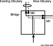
Important! At the head-end terminating node of the 1-way circuit, the traffic to be moved must be bridged to the new tributary. In UPSRs, the traffic to be moved must be bridged to the same new tributary on Main/Function/Growth 1 and Main/Function/Growth 2. At the head-end node of the 1-way circuit, select Configuration → Cross-Connections to access the Cross-Connection Wizard. Select Bridge a cross-connection from a source to multiple destinations and follow the directions to bridge the add cross-connection leg to the required new destination tributary(ies). The following figure shows an example of an add cross-connection leg bridged to new destination tributaries within a UPSR.  | ||||||
9 |
At the head-end node of the 1-way circuit, select View → Cross-Connections to access the cross-connection list and verify that the required add cross-connection leg was bridged to the new destination tributary(ies). | ||||||
10 |
Important! If the Tributary Monitoring Mode parameter is AUTO, the tributary automatically transitions to the in service state if a valid signal is detected and the tributary is monitored/alarmed. If the Tributary Monitoring Mode is NMON, the tributary is not monitored/alarmed, and the tributary will not automatically transition to the in service state if a valid signal is detected. At the head-end node of the 1-way circuit, select View → Equipment and verify the new Tributary parameters. If required, use Configuration → Equipment and refer to Chapter 4, Install and provision circuit packs/OLIUs procedures to perform additional provisioning. | ||||||
11 |
At each terminating (add/drop) and pass-through node (UPSRs only), click the Alarm List button to obtain an NE Alarm List and verify that no alarms are present. Clear all alarms before continuing this procedure. Reference: Alcatel-Lucent 1665 Data Multiplexer Extend (DMXtend) Alarm Messages and Trouble Clearing Guide, 365-372-326 | ||||||
12 |
Service interruption of up to 25 ms for STS or VT cross-connections may occur when performing the following roll procedures. In cases involving roll procedures from Main 2 cross-connections to Function slot ports, the service interruption may be as high as 200 ms.
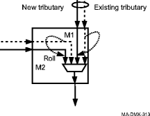
Service outage will occur if all new cross-connections are not properly made before performing the following roll procedures. Important! It is suggested that you use a Command Mode (cmdmde) of NORM when rolling a cross-connection input to a SONET interface. If the new input is being monitored and it is defective (for example: AIS-P, Loss of Pointer (LOP), STS UNEQ, B3 Signal Fail), the command will not complete. A Command Mode of FRCD allows the command to complete even if the new input is defective. When rolling a cross-connection input to a non-SONET interface, the new input is not monitored and the Command Mode must be set to FRCD. At the tail-end terminating node of the 1-way circuit, the traffic to be moved must be rolled to the new tributary. In UPSRs, the traffic to be moved must be bridged to the same new tributary on Main/Function/Growth 1 and Main/Function/Growth 2. At the tail-end node of the 1-way circuit, select Configuration → Cross-Connections to access the Cross-Connection Wizard. Select Roll a cross-connection from a source to a new source and follow the directions to roll the drop cross-connection leg(s) to the required new source tributary(ies). If a new Circuit Identifier (circuitid) is not specified, then the circuitid parameter value of the resultant cross-connection is inherited from the original cross-connection. If a new Circuit Identifier (circuitid) is null (circuitid=""), then the circuitid parameter value of the resultant cross-connection is cleared. The following figure shows an example of drop cross-connection legs rolled to new source tributaries within a UPSR.  | ||||||
13 |
At the tail-end node of the 1-way circuit, select View → Cross-Connections to access the cross-connection list and verify that the required drop cross-connection leg(s) was rolled to the new source tributary(ies). | ||||||
14 |
Important! If the Tributary Monitoring Mode parameter is AUTO, the tributary automatically transitions to the in service state if a valid signal is detected and the tributary is monitored/alarmed. If the Tributary Monitoring Mode is NMON, the tributary is not monitored/alarmed, and the tributary will not automatically transition to the in service state if a valid signal is detected. At the tail-end node of the 1-way circuit, select View → Equipment and verify the new Tributary parameters. If required, use Configuration → Equipment and refer to Chapter 4, Install and provision circuit packs/OLIUs procedures to perform additional provisioning. | ||||||
15 |
If moving a 2-way circuit, repeat Step 8 through Step 14 to move the traffic in the opposite direction of transmission to the new circuit path; otherwise, continue with the next step. | ||||||
16 |
At each terminating (add) and pass-through node (UPSRs only), select Configuration → Cross-Connections to access the Cross-Connection Wizard. Select Delete leg(s) of an existing cross-connection and follow the directions to delete the original cross-connections in the original circuit path. End of steps |