Ethernet transport over SONET/SDH
Overview
Alcatel-Lucent 1850 TSS-5 accepts Ethernet frames at an ingress port and transmits them out of one or more egress ports. The egress port(s) can be on the same network element or on a different network element. If it is on a different network element, Ethernet frames are transmitted over a SONET/SDH network. For Ethernet over SONET/SDH, the VLNC40/42/42B circuit pack transmits frames to the VLNC50/52/55 circuit pack over a Gigabit Ethernet link between the circuit packs, or over a Gigabit Ethernet link on the backplane. The VLNC50/52/55 circuit pack transmits them out of one or more of the egress ports to OC-n/STM-n SONET/SDH lines or a Gigabit Ethernet link. To transport an Ethernet frame across the SONET/SDH network, the Ethernet Frame is moved between a LAN port (VLNC35) and the SONET/SDH network.
Figure A-1: Ethernet over SONET/SDH transport through Alcatel-Lucent 1850 TSS-5 example
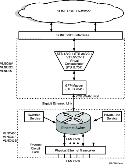
The following occurs to transport an Ethernet frame over a SONET/SDH network:
-
Alcatel-Lucent 1850 TSS-5 accepts an Ethernet Frame at an ingress LAN Port.
-
For Ethernet over SONET/SDH, the Ethernet frame is sent directly to the GFP mapper via a VCG port
-
The generic framing procedure (GFP) mapper encapsulates the Ethernet frame into a GFP Frame.
-
Virtual Concatenation maps the Ethernet stream into one or more SONET tributaries or SDH virtual containers (timeslots). This allows the network to carry traffic (Ethernet stream) at higher speeds than allowed by single tributaries or channels in either SONET or SDH. The group of virtually concatenated tributaries/VCs is referred to as a Virtual Concatenation Group (VCG).
-
The VCG is then placed on SONET/SDH tributaries/VCs and transmitted over the network.
Enhanced Ethernet features
The VLNC35 and VLNC50/52 circuit packs also provides the following enhanced Ethernet features.
-
TCAs on Ethernet PM error counts
- Link Capacity Adjustment Scheme (LCAS) per ITU G.7042
-
Client Signal Failure per ITU-T G.7041/Y.1303
Ethernet loopbacks
Alcatel-Lucent 1850 TSS-5 supports terminal loopbacks on VLNC35 Ethernet interfaces. Loopbacks may be used during installation and maintenance procedures to test the integrity of near and far-end interfaces as well as fibers and system circuitry.
Generic framing procedure (GFP)
Generic Framing Procedure (GFP) is used to encapsulate Ethernet frames for transport over a SONET/SDH network. Alcatel-Lucent 1850 TSS-5 uses frame-based GFP with the core header and no optional extension headers or Frame Check Sequence (FCS).
To encapsulate an Ethernet frame, the Ethernet preamble and Start of Frame Delimiter (SFD) fields are removed from the frame. A Type header and check (tHEC) is added to the Ethernet frame creating a GFP payload. The GFP payload is then scrambled and a Core header is added. The GFP frame is then sent to the Virtual Concatenator. The following figure shows the format of a GFP frame.
Figure A-2: GFP frame format
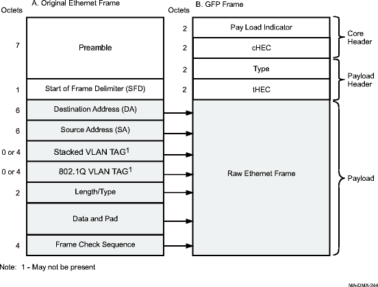
Table A-1: GFP frame format details
|
Section |
Field |
Description |
|---|---|---|
|
Core Header |
Payload Indicator (PLI) |
Binary number representing the number of octets in the GFP payload. |
|
Core Header Error Control (cHEC) |
CRC-16 checksum that protects the integrity of the contents of the Core Header. | |
|
Payload Header |
Type |
The type of information contained in the Payload field. The value is 01hex. |
|
Type Header Error Control (tHEC) |
CRC-16 checksum that protects the integrity of the contents of the Type Field. | |
|
Payload |
The raw Ethernet Frame (that is, the original Ethernet Frame without the Preamble and SFD. |
In the opposite direction when the GFP Mapper receives a GFP frame from the Virtual Concatenator, it removes the Core Header and, using the cHEC field, performs a Header Error Check. If the header is correct, the payload area of the GFP is then de-scrambled and the Type field and tHEC in the GFP header are checked for correctness. The Ethernet frame is extracted and the Preamble and SFD are added.
The GFP mapper at the far end of the network inserts idle GFP frames when there are no Ethernet frames to send. The near end GFP Mapper discards any idle GFP frames it receives over the SONET network. The idle GFP frames are not forwarded to the Ethernet Switch.
The GFP Mapper contains GFP queues that are used to store Ethernet frames while they are being processed.
The Generic Framing Procedure is defined in ITU-T G.7041/Y.1303 and ANSI T1X1.105 Sections 7.3.2 and 7.3.3.
Virtual concatenation
Virtual Concatenation is a standard inverse multiplex scheme for transporting a payload using multiple channels each of which has a lower capacity than the payload to be transported. It allows finer granularity in allocating the transport bandwidth than is available in standard contiguous concatenation (STS-3c/VC-4).
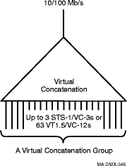
The grouped SONET/SDH tributaries or channels form a Virtual Concatenation Group (VCG). A VCG is treated as a single logical serial byte stream whose payload capacity equals that of the sum of the payload capacities of the constituent SONET/SDH tributaries or channels. The following figure shows a virtual concatenation group.
Figure A-3: Virtual concatenation group for VLNC50/52/55
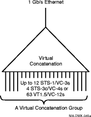
Figure A-4: Virtual concatenation group for VLNC35
Individual tributaries/VCs in the VCG are independently transported through the SONET/SDH network. Only the initial and final network nodes perform the Virtual Concatenation. Since the VCGs are invisible to the intermediate nodes, the intermediate nodes only need to transport normal SONET/SDH traffic and do not need to understand VCGs. This allows the tributaries/VCs to be transported through equipment which does not handle VCGs.
Differential delay buffers
Because the individual tributaries/VCs of a virtual concatenation group (VCAT) can take different paths through the network, they may experience different delays. VCG ports use differential delay buffers to accommodate differential delay. All VCAT and VCG functions for Ethernet over SONET/SDH are handled on the VLNC50/52/55 and VLNC35 circuit packs.
Link aggregation
Link aggregation allows multiple physical links between Ethernet switches to be treated as a single link. This provides for more bandwidth between the switches than can be transmitted over a single Ethernet port and it can provide protection from a cable, Ethernet port, or Ethernet circuit pack failure. Alcatel-Lucent 1850 TSS-5 supports Link Aggregation on the VLNC40/42/42B circuit pack. Alcatel-Lucent 1850 TSS-5 also supports transparency through the VLNC50/52/55, as well as the VLNC40/42/42B circuit pack. Transparency is supported on ports that have L2CP tunneling enabled but do not have Link Aggregation enabled.
Figure A-5: Link aggregation
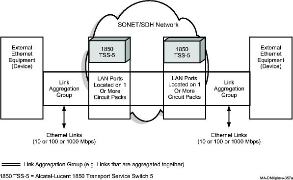
The figure shows two Ethernet devices running link aggregation interconnected via Ethernet circuit packs and a SONET Network. The Alcatel-Lucent 1850 TSS-5 shelves and the SONET network are invisible to the two Ethernet devices. The Ethernet traffic is transparently transferred between the external devices. Link aggregation is typically implemented using two dedicated unprotected point-to-point links (Ethernet Private Line Service) for each pair of external ports.
Link Aggregation is specified in IEEE 802.3 clause 43, formerly specified in 802.3ad. Link aggregation transparency does not require default VLAN ID.
Flow control
This section describes how Alcatel-Lucent 1850 TSS-5 controls the flow of Ethernet traffic. Alcatel-Lucent 1850 TSS-5 supports the following types of flow control:
Note:
In the Alcatel-Lucent 1850 Transport Service Switch (TSS-5) Command Line Interface Guide, flow control is referred to as storm control.
Local flow control (ingress traffic direction)
If the external equipment delivers Ethernet frames to the Ethernet circuit pack faster than they can be delivered across the network, the data buffers in the circuit pack (VLNC35, VLNC40/42/42B, VLNC50/52) fill up. When the data buffers reach the flow control threshold, the circuit pack initiates flow control. On full duplex links, the circuit pack issues a flow control request to the external equipment, requesting that the flow of frames be suspended.
Figure A-6: Local flow control of ingress traffic
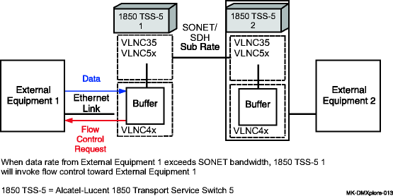
Note that this local flow control mechanism is concerned only with congestion (full packet buffers) at the local Alcatel-Lucent 1850 TSS-5. If Alcatel-Lucent 1850 TSS-5 at the other end of the SONET/SDH network is unable to deliver the Ethernet frames to the attached external equipment due to flow control conditions there, that does not directly affect the local flow control operation at the ingress Alcatel-Lucent 1850 TSS-5.
Local flow control (egress traffic direction)
If the local Ethernet circuit pack attempts to deliver Ethernet frames to the attached external equipment faster than the external equipment can accept them, the external equipment may initiate flow control. On full duplex links, the external equipment issues a flow control request to the Ethernet circuit pack requesting that the flow of frames be suspended.
End-to-end flow control
If the external equipment at the destination of an Ethernet connection cannot handle the rate of traffic being sent to it, it may be desirable to apply back pressure across the network to slow down the external source of the Ethernet traffic. This cross-network back pressure can only work well, however, when the source of the traffic can be identified unambiguously. Only the Ethernet Private Line Service offers this opportunity; thus, it is the only service that supports End-to-End Flow Control.
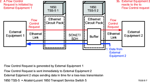
When end-to-end flow control is enabled, the circuit pack sends a flow control request across the SONET/SDH network immediately upon receiving a flow control request from external equipment.
Figure A-7: End-to-end flow control
Flow control provisioning
The Ethernet circuit packs automatically provide both local and end-to-end flow control if flow control is enabled for a LAN port. Similarly, disabling flow control for an LAN port disables both forms of flow control.
Table A-2: Flow control
|
LAN Port Flow Control State |
Flow Control Status |
Use/Comments |
|---|---|---|
|
Disabled |
Disabled |
Alcatel-Lucent 1850 TSS-5 does not participate in flow control. The LAN port does not respond to flow control requests. The LAN port does not generate flow control requests due to congestion. Flow control requests are transported when received. |
|
Enabled |
Enabled |
Flow control requirements are sent to the far-end Alcatel-Lucent 1850 TSS-5. LAN ports generate flow control requirements for fractional service. |
|
Drop |
Drop |
Disables Network-element controlled flow control and drops end-to-end flow control messages. |
Physical interface
Each Ethernet circuit pack contains a transceiver that implements the physical interface for that circuit pack's line type. For the 10/100 Mb/s circuit packs, this physical interface must be provisioned to or auto-negotiate to the proper line rate and duplex mode in order to communicate successfully with the connected equipment.
At the physical layer, many types of LANs can be used for multiple line rates and duplex modes. For example the LAN port on most PCs can be connected to a 10BASE-T (10 Mb/s) or a 100BASE-T (100 Mb/s) LAN. Before data traffic can be transmitted onto a LAN, all ports connected to the LAN must operate with the same line rate and duplex mode. LAN ports can either be provisioned with these values or provisioned to automatically negotiate (auto-negotiate) the values.
The VLNC40/42/42B supports 20 electrical 10/100BASE-T Ethernet ports on the shelf that can be used for multiple line rates and duplex modes. For example the LAN port on most PCs can be connected to a 10BASE-T (10 Mb/s) or a 100BASE-T (100 Mb/s) LAN. Before data traffic can be transmitted onto a LAN, all ports connected to the LAN must operate with the same line rate and duplex mode. LAN ports can either be provisioned with these values or provisioned to automatically negotiate (auto-negotiate) the values.
Auto-negotiation
In the auto-negotiation process, a LAN port advertises its acceptable parameters, compares these with the advertised parameters of its link partner, and then agrees upon a set of parameters with the link partner. IEEE 802.3 allows the line rate, duplex mode, and flow control mode to be auto-negotiated. A LAN port not configured to support auto-negotiation will use provisioned values for these parameters. A LAN port configured for auto-negotiation that is connected to a LAN port not configured for auto-negotiation will follow prescribed rules for parameter settings.
In Alcatel-Lucent 1850 TSS-5, auto-negotiation is available on all Ethernet ports.
Table A-3: Line rate operation for shelf-based electrical ports
|
Alcatel-Lucent 1850 TSS-5 LAN Port Rate Provisioning |
Connected Equipment Provisioning |
Ethernet Link Rate 1 | |
|---|---|---|---|
|
Auto-Negotiation |
Advertised/Set at | ||
|
10 |
Disabled |
10 |
10 |
|
Disabled |
100 |
No Link | |
|
Enabled |
10 |
10 | |
|
Enabled |
100 |
No Link | |
|
Enabled |
10/100 |
10 | |
|
100 |
Disabled |
10 |
No Link |
|
Disabled |
100 |
100 | |
|
Enabled |
10 |
No Link | |
|
Enabled |
100 |
100 | |
|
Enabled |
10/100 |
100 | |
|
Auto |
Disabled |
10 |
10 |
|
Disabled |
100 |
100 | |
|
Enabled |
10 |
10 | |
|
Enabled |
100 |
100 | |
|
Enabled |
10/100 |
100 | |
Notes:
Both the Alcatel-Lucent 1850 TSS-5 and the connected equipment will try to determine a common line rate. The link will not come up if both ends have auto-negotiation enabled and advertise incompatible duplex modes.
Table A-4: PTM rate and flow control operation
|
GE optical |
FE optical |
GE electrical | |
|---|---|---|---|
|
Auto-negotiation |
Yes |
No |
Yes |
|
Duplex mode |
Full |
Full |
Full |
|
Flow control |
yes/no/auto |
yes/no |
yes/no/auto |
|
Master/slave operational value |
NA |
NA |
multiport device |
|
Crossover mode |
NA |
NA |
Auto-detection |
Table A-5: Flow control operation
|
LAN Port Provisioning |
Connected Equipment Provisioning |
Duplex Mode State |
Comments | |||
|---|---|---|---|---|---|---|
|
Flow Control |
Auto-Negotiation State |
Auto-Negotiation |
Advertised/ Set at 1 |
Alcatel-Lucent 1850 TSS-5 2 |
Connected Equipment | |
|
Auto |
Enabled |
Disabled |
Disabled |
Enabled |
Disabled |
Inconsistent Provisioning |
|
Enabled |
Enabled |
Enabled |
Inconsistent Provisioning | |||
|
Enabled |
Disabled |
Enabled |
Disabled |
|||
|
Enabled |
Enabled |
Enabled |
||||
|
Enabled |
Enabled |
Disabled |
Disabled |
Enabled |
Disabled |
Inconsistent Provisioning |
|
Enabled |
Enabled |
Enabled |
Inconsistent Provisioning | |||
|
Enabled |
Disabled |
Enabled |
Disabled |
|||
|
Enabled |
Enabled |
Enabled |
||||
|
Disabled |
Disabled |
Disabled |
Enabled |
Disabled |
Inconsistent Provisioning | |
|
Enabled |
Enabled |
Enabled |
||||
|
Enabled |
Disabled |
Enabled |
Unknown |
Inconsistent Provisioning | ||
|
Enabled |
Enabled |
Unknown |
Inconsistent Provisioning | |||
|
Disabled |
Enabled |
Disabled |
Disabled |
Disabled |
Disabled |
Inconsistent Provisioning |
|
Enabled |
Disabled |
Enabled |
Inconsistent Provisioning | |||
|
Enabled |
Disabled |
Disabled |
Disabled |
|||
|
Enabled |
Disabled |
Disabled |
||||
|
Disabled |
Disabled |
Disabled |
Disabled |
Disabled |
||
|
Enabled |
Disabled |
Enabled |
Inconsistent Provisioning | |||
|
Enabled |
Disabled |
Disabled |
Unknown |
Inconsistent Provisioning | ||
|
Enabled |
Disabled |
Unknown |
Inconsistent Provisioning | |||
Notes:
Flow control will only be enabled if the connected equipment is capable of Symmetric Flow Control.
IEEE 802.3 does not define flow control states for half duplex links or when only one side of a linkis provisioned for auto-negotiation. This is the expected behavior of the connected equipment.
IEEE 802.3 recommends that equipment be configured for auto-negotiation to avoid inconsistentprovisioning.
Queues and buffers
Ethernet circuit packs contain small buffer pools that provide storage of Ethernet frames for brief periods of congestion or until flow control requests can be honored. These small buffer pools are associated with the Ethernet switch and the Generic Framing Procedure (GFP) mechanism. The GFP mechanism is described further in Generic framing procedure (GFP). A larger buffer pool designed to handle different path lengths for individual STS-1/VC-3s, STS3c/VC-4s, or VT1.5/VC-12s is associated with the virtual concatenation process. Its function is described in more detail in Virtual concatenation. Two priority-based queues are provided to allow high priority traffic to be forwarded ahead of low priority traffic.