Sparing graph
 Overview
This section provides guidelines and a procedure to determine the number of spares needed at each location. The number of spares for each circuit pack must be determined and maintained separately, based on that code's in-service population at each given location.
Using the sparing graph
Use the following procedure to determine how many spare circuit packs, port units, or other pieces of equipment are required for each code at each location to maintain 99.9% service continuity, given a ten day lead time.
1 |
Locate the failure rate for the unit under consideration using the tables above. |
2 |
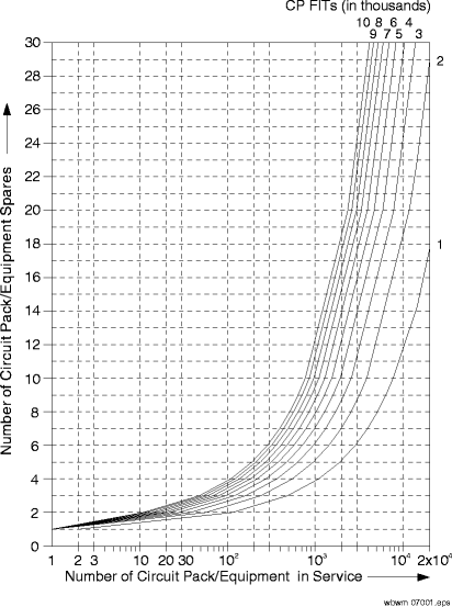
Refer Figure 7-1, Sparing graph for a 10-day lead time and select the curve that represents the nearest failure rate. Interpolation may be necessary. |
3 |
Follow the curve until it intersects the vertical line that represents the number of units in service at the given location. Interpolation may be necessary. |
4 |
Refer to the horizontal line immediately above the intersection. The number associated with this line is the minimum number of spares recommended for that location. |
5 |
Repeat steps 1–4 for each circuit pack, port unit, and type of equipment listed in the tables above. Example of using the graph If there are 100 VLNC50 OC-3 OLIUs (failure rate of 3619) in service at a given location and your lead time is 10 days, then you should order and stock 3 spare OC-3 OLIUs port units for that location. Sparing graph for a 10-day lead time Use the graph below to plan the number of spares necessary for the circuit packs and equipment used in Alcatel-Lucent 1850 TSS-5. Figure 7-1: Sparing graph for a 10-day lead time
End of steps |