Link aggregation
Overview
Alcatel-Lucent 1850 TSS-5 supports link aggregation on the VLNC40/42/42B circuit pack. The ports comprising a link aggregation group (LAG) must be located on the same pack. Link aggregation can also provide facility protection on VLNC40/42/42B LAN ports.
Note:
LAG is not allowed on ports associated with an ERP instance.
Hitless bandwidth increase/decrease
Ordinarily, multiple Ethernet links between two bridges form loops (unless a spanning tree blocks all but one) so they cannot be used to increase bandwidth. Link aggregation causes defined groups of links to be treated as a single logical link, making multiple LAN ports appear as one. In this manner, bandwidth can be increased without requiring an upgrade to a higher rate link.
Facility protection
Link aggregation can provide facility protection by removing failed links automatically. When a link fails, traffic is shifted to the remaining links in that LAG. More links than are needed can be added to the group and each is active until it fails (similar to utilizing LCAS protection for SONET tributaries).
Link aggregation control protocol
Link aggregation is specified in IEEE 802.3 clause 43, formerly specified in 802.3ad. A VLNC40/42/42B can be configured to either use this standard protocol to control link aggregation (which negotiates with the equipment at the other end of the link) or to simply force aggregation without a control protocol.
General link aggregation rules
Link aggregation follows these basic guidelines:
-
Available for LAN ports on the VLNC40/42/42B circuit pack
-
Maximum of 12 LAGs per pack and 8 ports per LAG.
-
The ports in a LAG must be on the same pack, and be functioning at the same rate (for example, 10 or 100 Mbps).
-
All links in a LAG are in-service until they fail.
-
A LAG behaves like a logical port; features like VLAN assignments should be provisioned on the LAG. VLAN assignments and other features provisioned on LAG member ports are not operational while a port is a member of the LAG.
Link aggregation example
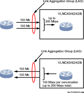
The figure below depicts link aggregation on two VLNC40/42/42B LAN ports at 100 Mbps. The top portion of the figure shows two ports receiving separate inbound conversations. The bottom portion depicts the same two conversations being split between the two outbound ports in the LAG. In this example, no failure has occurred and both ports comprising the LAG are in-service.
Traffic entering incoming ports is aggregated into a LAG. While ports are in-service, outgoing traffic is split among working ports by conversations defined by the distribution function.
Figure 5-11: Link aggregation at 100 Mbps (all ports in-service)

Figure 5-11, Link aggregation at 100 Mbps (all ports in-service) represents an ideal case, in which there are at least 2 conversations, each a maximum of 100 Mbps. In this case, they can be equally split over the two ports comprising the LAG. The ability to split the two conversations across multiple ports also depends on the distribution of MAC/IP addresses.
Link aggregation employs an algorithm that assigns traffic to member ports to prevent misordering. A given conversation can be assigned to only one port and cannot be split across multiple ports in the same LAG. A conversation is defined by an IP source and destination pair (for IP packets) and by a MAC source and destination pair (for non-IP packets). The algorithm uses the XOR of the three least significant bits of the address pairs to assign a port/link. Therefore, the actual load balancing achieved depends on the distribution of MAC/IP addresses.
VCG LAG
Release 7.1 supports LAG between two Alcatel-Lucent 1850 TSS-5 nodes or between a Alcatel-Lucent 1850 TSS-5 and Alcatel-Lucent 1850 Transport Service Switch 100 in an Ethernet over SONET/SDH network.
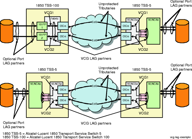
This feature uses an internal port-to-VLAN mapping (frame tagging/stripping) mechanism to enable a mapping of LAG port members on a VLNC42/42B circuit pack to individual VCG private line connections on a VLNC5x circuit pack, multiplexing the two LAG member ports' traffic over a single backplane GbE connection between them. It also uses an internal signaling mechanism to convey VCG faults to the LAG for fast switching.
Important!
Only one VCG LAG application is supported per Alcatel-Lucent 1850 TSS-5.
VCG LAG example
LAG partner systems use the standard (802.3) Link Aggregation Control Protocol (LACP) to manage the state of LAG port members. This includes the ability to signal member status changes (for example, failed or recovered) to the far-end LAG partner so that traffic is only passed on good links.
The Alcatel-Lucent 1850 TSS-5 and Alcatel-Lucent 1850 Transport Service Switch 100 also support fast LAG. This provides fast resilient Ethernet connections in networks. In order for the LAG partners to quickly communicate failures and facilitate fast LAG switching, faults are communicated using a protocol understood by each LAG partner. The Alcatel-Lucent 1850 Transport Service Switch 100 uses the GFP CSF fault to trigger a switch. The associated Alcatel-Lucent 1850 TSS-5 LAG partner resides on the VLNC42/42B circuit pack. The VLNC42/42B circuit pack does not support VCGs and GFP CSF faults. Therefore, an internal ETH-VSF (Vendor Specific Fault) protocol is used to trigger an equivalent switch on the VLNC42/42B circuit pack.
Figure 5-12: LAG over EoS network application

The VLNC5x circuit pack GbE port (d1-1) is connected via the backplane to the VLNC42/42B circuit pack GbE port (d2-4).
The traffic on VLNC42/42B ports d2-3 and d2-4 (P3 and P4) can be marked with VLAN tags to identify its original port and multiplexed over the backplane GbE port (d2-4) to VCGs on the VLNC5x circuit pack.
Up to 120 VLAN entries are supported to classify traffic. Untagged traffic is always mapped to a LAG VCG. Mapping non-LAG traffic to the other six VCGs on the VLNC5x circuit pack is supported.
Link pass through
Link pass through (LPT) allows Provider Equipment that supports Ethernet Service OAM to communicate fault information, making a point-to-point Ethernet service connection appear more like a direct connection between remote CE ports. If the UNI link goes down at one end (or the Provider transport fails in between), then the UNI link goes down at the other end.
Detection of certain defects on an UNI-N, triggers the sending of ETH-CSF messages of type LOS by the Up-MEP to the remote Up-MEP on the peer UNI-N. Upon the reception of the ETH-CSF frame with type LOS, the remote Up-MEP’s UNI-N port is shutdown.
LPT may be enabled or disabled on an Up-MEP. When enabled, the ETH-CSF frames are sent at 1-minute periods (with a there-frame burst on initiation). Link shutdown, that is a consequent action of reception of ETH-CSF, is also configurable on an Up-MEP.