Procedure 6-6: Replace pluggable transmission module
 Required equipment
The following Class 1 SFP transceivers are Alcatel-Lucent approved.
|
Name/Qualifier |
Pluggable Transmission Module Code/Comcode/Part Number |
Description |
Compatible Circuit Packs |
|---|---|---|---|
|
OMFE/100BASE-LX-SM |
100BASE-LX-I1 109527812 |
100 Mb/s optical Fast Ethernet SFP TRCVR |
VLNC33 VLNC35 VLNC40 VLNC42 VLNC42B VLNC60 VLNC61 VLNC62 VLNC64 |
|
OM1G/1000BASE-ZX |
1000BASE-ZX-I1 109541862 |
GbE SM 1550 nm 1000BASE-ZX SFP TRCVR |
VLNC40 VLNC42 VLNC42B VLNC50 VLNC52 VLNC55 |
|
EM1G//EMFE/1000BASE-T// 100BASE-T |
BASE-T-C1 109565549 |
10 Mb/s, 100 Mb/s and GbE, Copper, SFP TRCVR |
VLNC40 VLNC42 VLNC42B VLNC50 VLNC52 VLNC55 VLNC60 VLNC61 VLNC62 VLNC64 |
|
OM1G/1000BASE-LX |
GE-1X2XFC-LX-I1 109568782 |
GbE SM 1310 nm 1XFC/2XFC 1000BASE-LX SFP TRCVR |
VLNC40 VLNC42 VLNC42B VLNC50 VLNC52 VLNC55 VLNC60 VLNC61 VLNC62 VLNC64 |
|
OM1G/1000BASE-SX |
GE-1X2XFC-SX-I1 109570606 |
GbE MM 850 nm 1XFC/2XFC 1000BASE-SX SFP TRCVR |
VLNC40 VLNC42 VLNC42B VLNC50 VLNC52 VLNC55 VLNC60 VLNC61 VLNC62 VLNC64 |
|
OM622//OM1G/40KMBIDI// 1000BASE-BX40 |
GE-131T149R-I1 109703215 |
Bidirectional SFP, 1000BASE-BX40, OC-12/STM-4 40km, SM, 1310 nm Tx, 1490 nm Rx |
VLNC40 VLNC42 VLNC42B VLNC50 VLNC52 VLNC55 VLNC60 VLNC61 VLNC62 VLNC64 |
|
OM622//OM1G/40KMBIDI// 1000BASE-BX40 |
GE-149T131R-I1 109703207 |
Bidirectional SFP, 1000BASE-BX40, OC-12/STM-4 40km, SM, 1490 nm Tx, 1310 nm Rx |
VLNC40 VLNC42 VLNC42B VLNC50 VLNC52 VLNC55 VLNC60 VLNC61 VLNC62 VLNC64 |
|
OM155//OM622/40KMBIDI// 40KMBIDI |
622-131T155R-I1 109703165 |
Bidirectional SFP, OC-3/ STM-1/OC-12/STM-4, 40 km, SM, 1310 nm Tx, 1550 nm Rx |
VLNC50 VLNC52 VLNC55 |
|
OM155//OM622/40KMBIDI// 40KMBIDI |
622-155T131R-I1 109703181 |
Bidirectional SFP, OC-3/ STM-1/OC-12/STM-4, 40 km, SM, 1550 nm Tx, 1310 nm Rx |
VLNC50 VLNC52 VLNC55 |
|
OM155//OM622//2.5G 1.3IR1//1.3IR1//1.3IR1 |
OC3X12X48-IR1-I1 109708131 |
OC3/STM1/OC12/ STM4/OC48/STM16, 1310nm, 15 km, SFP TRCVR |
VLNC55 |
|
OM155//OM622//2.5G 1.3LR1//1.3LR1//1.3LR1 |
OC3X12X48-LR1-I1 109708149 |
OC3/STM1/OC12/ STM4/OC48/STM16, 1310nm, 40km, 15 km, SFP TRCVR |
VLNC55 |
|
OM155/IR1(S-1.1) |
OC3IR1-I1 109453894 |
OC3 IR1, SM, 1310 nm, 15 km, SFP TRCVR |
VLNC50 VLNC52 VLNC55 VLNC64 |
|
OM155/LR1(L-1.1) |
OC3LR1-I1 109453886 |
OC3 LR1, SM, 1310 nm, 40 km, SFP TRCVR |
VLNC50 VLNC52 VLNC55 VLNC64 |
|
OM622/IR1(S-4.1) |
OC12IR1-I1 109453902 |
OC12 IR1, SM, 1310 nm, 15 km, SFP TRCVR |
VLNC50 VLNC52 VLNC55 |
|
OM622/LR1(L-4.1) |
OC12LR1-I1 109467522 |
OC12 LR1, SM, 1310 nm, 40 km, SFP TRCVR |
VLNC50 VLNC52 VLNC55 |
|
OM622/LR2(L-4.2) |
OC12LR2-I1 109604447 |
OC12 LR2, SM, 1550 nm, 80 km, SFP TRCVR |
VLNC50 VLNC52 VLNC55 |
|
OM2.5G/1.3LR1 |
OC48LR1-I1 109493528 |
OC48 LR1, SM, 1310 nm, 40 km, SFP TRCVR |
VLNC55 |
|
OM2.5G/1.5LR2 |
OC48LR2-I1 109504431 |
OC48 LR2, SM, 1550 nm, 80 km, SFP TRCVR |
VLNC55 |
|
OM2.5G/1.3SR1 |
OC48SR1-I1 109564518 |
OC48 SR1, SM, 1310 nm, 2 km, SFP TRCVR |
VLNC55 |
|
OM155/SR1(I-1) |
S155I2 109602599 |
OC-3 SR-1/STM-1, SM, 1310 nm, 2 km, SFP TRCVR |
VLNC50 VLNC52 VLNC55 VLNC64 |
|
OM2.5G/SL-16.2 |
S2G7C47LI 1AB402160002 |
OC48/STM16 CWDM 1471 nm, SFP TRCVR S-C8L1-1D2 : S-C8L1-1D5 |
VLNC55 |
|
OM2.5G/SL-16.2 |
S2G7C49LI 1AB402160003 |
OC48/STM16 CWDM 1491 nm, SFP TRCVR S-C8L1-1D2 : S-C8L1-1D5 |
VLNC55 |
|
OM2.5G/SL-16.2 |
S2G7C51LI 1AB402160004 |
OC48/STM16 CWDM 1511 nm, SFP TRCVR S-C8L1-1D2 : S-C8L1-1D5 |
VLNC55 |
|
OM2.5G/SL-16.2 |
S2G7C53LI 1AB402160005 |
OC48/STM16 CWDM 1531 nm, SFP TRCVR S-C8L1-1D2 : S-C8L1-1D5 |
VLNC55 |
|
OM2.5G/SL-16.2 |
S2G7C55LI 1AB402160006 |
OC48/STM16 CWDM 1551 nm, SFP TRCVR S-C8L1-1D2 : S-C8L1-1D5 |
VLNC55 |
|
OM2.5G/SL-16.2 |
S2G7C57LI 1AB402160007 |
OC48/STM16 CWDM 1571 nm, SFP TRCVR S-C8L1-1D2 : S-C8L1-1D5 |
VLNC55 |
|
OM2.5G/SL-16.2 |
S2G7C59LI 1AB402160008 |
OC48/STM16 CWDM 1591 nm, SFP TRCVR S-C8L1-1D2 : S-C8L1-1D5 |
VLNC55 |
|
OM2.5G/SL-16.2 |
S2G7C61LI 1AB402160009 |
OC48/STM16 CWDM 1611 nm, SFP TRCVR S-C8L1-1D2 : S-C8L1-1D5 |
VLNC55 |
|
OM155//OM622/CWDM-LR |
S622C47EL 109664086 |
OC-3/STM-1/OC-12/STM-4 CWDM, 1471 nm, SFP TRCVR |
VLNC50 VLNC52 VLNC55 VLNC64 |
|
OM155//OM622/CWDM-LR |
S622C49EL 109664094 |
OC-3/STM-1/OC-12/STM-4 CWDM, 1491 nm, SFP TRCVR |
VLNC50 VLNC52 VLNC55 VLNC64 |
|
OM155//OM622/CWDM-LR |
S622C51EL 109664102 |
OC-3/STM-1/OC-12/STM-4 CWDM, 1511 nm, SFP TRCVR |
VLNC50 VLNC52 VLNC55 VLNC64 |
|
OM155//OM622/CWDM-LR |
S622C53EL 109664110 |
OC-3/STM-1/OC-12/STM-4 CWDM, 1531 nm, SFP TRCVR |
VLNC50 VLNC52 VLNC55 VLNC64 |
|
OM155//OM622/CWDM-LR |
S622C55EL 109664128 |
OC-3/STM-1/OC-12/STM-4 CWDM, 1551 nm, SFP TRCVR |
VLNC50 VLNC52 VLNC55 VLNC64 |
|
OM155//OM622/CWDM-LR |
S622C57EL 109664136 |
OC-3/STM-1/OC-12/STM-4 CWDM, 1571 nm, SFP TRCVR |
VLNC50 VLNC52 VLNC55 VLNC64 |
|
OM155//OM622/CWDM-LR |
S622C59EL 109664144 |
OC-3/STM-1/OC-12/STM-4 CWDM, 1591 nm, SFP TRCVR |
VLNC50 VLNC52 VLNC55 VLNC64 |
|
OM155//OM622/CWDM-LR |
S622C61EL 109664151 |
OC-3/STM-1/OC-12/STM-4 CWDM, 1611 nm, SFP TRCVR |
VLNC50 VLNC52 VLNC55 VLNC64 |
|
OM1G/1000BASE-LCWDM |
SGEC47EL 109669622 |
GbE CWDM, 1471 nm, SFP TRCVR |
VLNC40 VLNC42 VLNC42B VLNC50 VLNC52 VLNC55 VLNC60 VLNC61 VLNC62 VLNC64 |
|
OM1G/1000BASE-LCWDM |
SGEC49EL 109669630 |
GbE CWDM, 1491 nm, SFP TRCVR |
VLNC40 VLNC42 VLNC42B VLNC50 VLNC52 VLNC55 VLNC60 VLNC61 VLNC62 VLNC64 |
|
OM1G/1000BASE-LCWDM |
SGEC51EL 109669648 |
GbE CWDM, 1511 nm, SFP TRCVR |
VLNC40 VLNC42 VLNC42B VLNC50 VLNC52 VLNC55 VLNC60 VLNC61 VLNC62 VLNC64 |
|
OM1G/1000BASE-LCWDM |
SGEC53EL 109669655 |
GbE CWDM, 1531 nm, SFP TRCVR |
VLNC40 VLNC42 VLNC42B VLNC50 VLNC52 VLNC55 VLNC60 VLNC61 VLNC62 VLNC64 |
|
OM1G/1000BASE-LCWDM |
SGEC55EL 109669663 |
GbE CWDM, 1551 nm, SFP TRCVR |
VLNC40 VLNC42 VLNC42B VLNC50 VLNC52 VLNC55 VLNC60 VLNC61 VLNC62 VLNC64 |
|
OM1G/1000BASE-LCWDM |
SGEC57EL 109669671 |
GbE CWDM, 1571 nm, SFP TRCVR |
VLNC40 VLNC42 VLNC42B VLNC50 VLNC52 VLNC55 VLNC60 VLNC61 VLNC62 VLNC64 |
|
OM1G/1000BASE-LCWDM |
SGEC59EL 109669689 |
GbE CWDM, 1591 nm, SFP TRCVR |
VLNC40 VLNC42 VLNC42B VLNC50 VLNC52 VLNC55 VLNC60 VLNC61 VLNC62 VLNC64 |
|
OM1G/1000BASE-LCWDM |
SGEC61EL 109669697 |
GbE CWDM, 1611 nm, SFP TRCVR |
VLNC40 VLNC42 VLNC42B VLNC50 VLNC52 VLNC55 VLNC60 VLNC61 VLNC62 VLNC64 |
Refer to the Alcatel-Lucent 1850 Transport Service Switch (TSS-5) Installation and System Turn-Up Guide, as required, when removing and/or installing pluggable transmission modules.
 Before you begin
Prior to performing this procedure:
-
Refer to Laser safety and Electrostatic discharge information in Chapter 1, Safety.
-
View office records and/or select View → Equipment to determine the correct type of pluggable transmission module to be replaced.
-
Ensure that the correct pluggable transmission module is available for replacement.
Steps
Complete the following steps to replace a pluggable transmission module.
1 |
Remove the cables from the required pluggable transmission module. | ||||||||||||
2 |
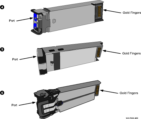
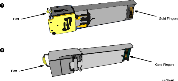
Referring to the figure below, determine the type of latching mechanism on the pluggable transmission module you have. 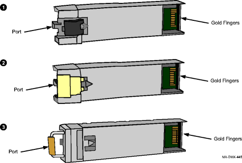
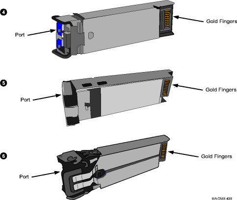
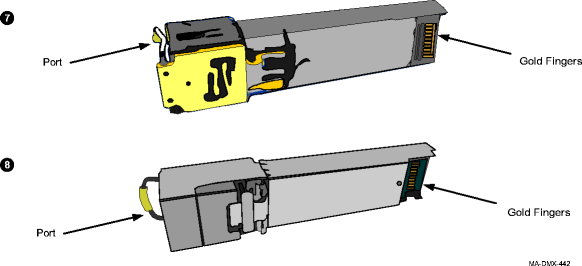 | ||||||||||||
3 |
Referring to Step 2, what type of latching mechanism does your module have?
| ||||||||||||
4 |
Before removing the module, the latch must be in the open position. Open the swivel latch and pull gently on the latch to remove the pluggable transmission module from the socket. Figure 6-8, Latch type 3 (opened and closed) shows the open and closed position of the latch. Depending on your pluggable transmission module type, the appearance of the port opening and latch mechanism may vary. Figure 6-8: Latch type 3 (opened and closed)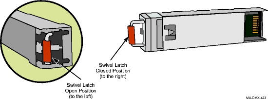 | ||||||||||||
5 |
Proceed to Step 7. | ||||||||||||
6 |
Before removing the module, the latch must be in the open position. Open the swivel latch and pull gently on the latch to remove the pluggable transmission module from the socket. Figure 6-9, Latch type 4, 5, 6, 7, and 8 (opened and closed) shows the open and closed position of the latch. Depending on your PTM type, the appearance of the port opening and latch mechanism may vary. Figure 6-9: Latch type 4, 5, 6, 7, and 8 (opened and closed)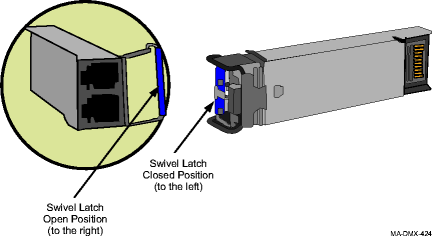 | ||||||||||||
7 |
Important! It is recommended that dust covers be installed into the ports on optical pluggable transmission modules to maintain cleanliness until the cable is connected. Electrical pluggable transmission modules do not require dust covers. If you just removed an optical pluggable transmission module, install dust covers into the ports to maintain cleanliness. | ||||||||||||
8 |
Before installing the replacement transmission module, hold the connector/latch-end of the module in your left hand with the gold fingers facing you. The module should be positioned in manner similar to Figure 6-10, Pluggable transmission module with dust cover (optical only). Figure 6-10: Pluggable transmission module with dust cover (optical only)
Important! If you are installing an optical module, do not remove the dust cover until you are ready to connect cabling or if you need to clean the module. Dust covers There are a variety of different types of dust covers. Any of the following examples could be similar to the dust cover in your optical pluggable transmission module. Figure 6-11: Examples of dust covers | ||||||||||||
9 |
Refer to the following figure and determine the type of latching mechanism on the pluggable transmission module you have. 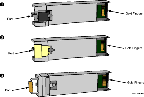
 | ||||||||||||
10 |
Important! Optical pluggable transmission modules are shipped with a dust cover installed into the optical ports to maintain cleanliness during storage and/or transportation. It is recommended that the dust cover be kept in place to maintain cleanliness until the optical fiber is connected. With proper care and handling, cleaning the pluggable transmission modules should not be necessary. If required, clean the optical pluggable transmission module. Reference: Procedure 6-18: Clean pluggable transmission module | ||||||||||||
11 |
Referring to Step 9, what type of latching mechanism does your module have?
| ||||||||||||
12 |
Before inserting the module, the latch must be in the closed position. On an optical pluggable transmission modules, the latch is in the closed position when the dust cover is in place. Figure 6-12, Latch type 3 (opened and closed) shows the open and closed position of the latch. Depending on your pluggable transmission module type, the appearance of the port opening and latch mechanism may vary. Figure 6-12: Latch type 3 (opened and closed)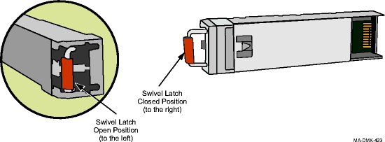 | ||||||||||||
13 |
Proceed to Step 15. | ||||||||||||
14 |
Before inserting the module, the latch must be in the closed position. When the dust cover is in place on an optical pluggable transmission module, the latch is in the closed position. Figure 6-13, Latch type 4, 5, 6, 7, and 8 (opened and closed) shows the open and closed position of the latch. Depending on your PTM type, the appearance of the port opening and latch mechanism may vary. Figure 6-13: Latch type 4, 5, 6, 7, and 8 (opened and closed)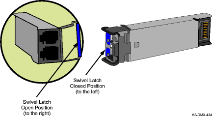 | ||||||||||||
15 |
With your left hand, hold the pluggable transmission module by the port end or dust cover. The ports are in your left hand and the gold fingers are visible (facing you). (Do not insert pluggable transmission module.) | ||||||||||||
16 |
Rotate the module; the port end or dust cover is facing you and the gold fingers are facing the floor. (Do not insert pluggable transmission module). | ||||||||||||
17 |
Push on the dust cover to insert the pluggable transmission module in the required socket of the circuit pack faceplate. The latch automatically catches when the pluggable transmission module is inserted. To verify that the pluggable transmission module is properly latched in the cage, gently pull the pluggable transmission module (parallel to the direction the pluggable transmission module was installed). Do not rotate the swivel latch or activate the de-latching feature on the pluggable transmission module. The pluggable transmission module is secure. Verify that all unused sockets on the circuit pack are equipped with dust covers. Figure 6-14: Insert pluggable transmission module into socket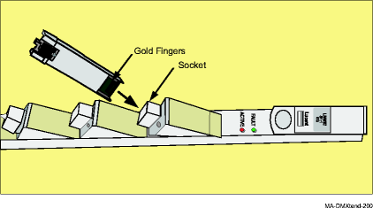
Result: If the pluggable transmission module fails when inserted into the VLNC5x circuit pack, and another pluggable transmission module in the shelf fails at the same time, replace the newly-installed pluggable transmission module. Each pluggable transmission module has unique internal data for warranty purposes. If this data for any reason is not unique, both pluggable transmission modules with the duplicated information will be declared failed. If the pluggable transmission module fails when inserted into the VLNC5x circuit pack, select View → Equipment to access the port and verify that the port Signal Type parameter is provisioned correctly (OC3 is the default.) If required, select Configuration → Equipment to access the required port and provision the port Signal Type parameter correctly. | ||||||||||||
18 |
Reconnect the cables. | ||||||||||||
19 |
From the System View window, click the Alarm List button to obtain the NE Alarm List and verify that no alarms are present for the port on the pluggable transmission module just installed. If required, refer to the appropriate procedure to clear any alarms present for the required port. | ||||||||||||
20 |
From the System View menu, select View → Equipment to access the port parameters for the pluggable transmission module just installed and verify that the parameters are intact. If required, refer to the appropriate procedure in the Alcatel-Lucent 1850 Transport Service Switch (TSS-5) User Provisioning Guide to change any port parameters. For a detailed description of the Web-based GUI used to interface with the VLNC40/42/42B, VLNC60/61/62, and VLNC64 circuit packs and general information about using the Web-based GUI, refer to Alcatel-Lucent 1850 Transport Service Switch (TSS-5) CLI User Provisioning Guide. For a detailed description of the Command Line Interface (CLI) messages used to interface with the VLNC40/42/42B, VLNC60/61/62, and VLNC64 circuit packs and general information about using the Command Line Interface (CLI), refer to Alcatel-Lucent 1850 Transport Service Switch (TSS-5) Command Line Interface Guide. End of steps |