Bandwidth calculations and rate shaping on T-MPLS NNIs
Overview
As an Ethernet packet passes through the VLNC42B, more bytes are added to the packet. As a result, more bandwidth is consumed on the NNI port than was injected into the UNI port(s) [traffic from multiple UNI ports can converge on a single NNI port]. As a result, it is not possible to inject 1 Gb/s of traffic on a UNI port and have all of that traffic delivered out of a 1 Gb/s NNI port. An attempt to do that will lead either to packet drops or traffic throttling due to flow control. The impact of this added traffic is packet-size dependent, with the effect being greater on smaller packets than on larger packets.
Another, much smaller, contributor to traffic expansion is the internal generation of OAM packets. A fixed allocation of 10 Mb/s of such traffic is assumed. This is sufficient to handle the worst case OAM provisioning.
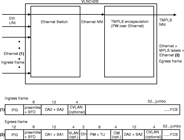
Figure 14-1, VLNC42B Ethernet packet processing on TMPLS shows how an Ethernet packet received on a UNI is transformed as it is processed by the VLNC42B devices and as it is transmitted on a T-MPLS NNI.
Table 14-3, Recommended rate shape settings shows the recommended rate shape settings for various packet sizes. All calculations and recommended rate shape values assume that there is no NNI-to-NNI transit traffic (LSR traffic) on the node (that is, all traffic on the NNI originates from local UNIs (LER traffic). The calculations and rate shape values should be adjusted on NNIs that carry a mix of LSR traffic and LER traffic.
Also see Procedure 14-9: Manage traffic expansion in TMPLS pseudowire encapsulation.
Figure 14-1: VLNC42B Ethernet packet processing on TMPLS

Frame processing:
-
VLAN is optional (configurable per tunnel). This is the VLAN ID referenced in the L2 encapsulation profile.
-
Eth = 0x8847 (marks the Eth payload to be MPLS).
-
CW (control word) is optional (configurable per pseudo-wire. CW is enabled/disabled in Create Terminated PW.
-
DA1 and SA1 are the DA (destination address) and SA (source address) added by the Ethernet processor.
-
DA2 and SA2 are the DA and SA as received from a UNI
In general there will be a mix of tunnels and pseudo-wires with and without VLAN and with and without Control Word. Assuming no CW (on any PW) and no VLAN (on any Tunnel), the T-MPLS overhead is 22 bytes.
Additional overhead caused by OAM CV messages
An MPLS NNI port may support up to 64 OAM sessions (1 per tunnel). An OAM session can generate connectivity verification (CV) packets with a 3.3 msec interval (300 per second). A CV message is 64 bytes (plus 22 when including the MPLS overhead). The maximum number of CV messages transmitted per second equals 64*300 = 19,200. The internal rate shape value should be adjusted down with the value: 19,200 * 8 * 64 = 9,830 Kbits/sec.
CAC checks
After the rate shape value is established it is used as a ceiling for all call admission control (CAC) checks. The CAC checks are as follows:
-
Sum of CIR values of all created tunnels <= egress rate shape value.
-
PIR values of all created tunnels <= egress rate shape value.
-
Sum of CIR values of all created pseudoWires in a tunnel <= CIR value of the tunnel.
-
PIR values of all created pseudowires in a tunnel <= PIR value of the tunnel.
-
Sum of CIR values of all active ETS flows in an (active) pseudowire <= CIR value of the pseudowire
-
PIR values of all active ETS flows in an (active) pseudoWires <= PIR value of the pseudowire.
The ETS flows only support single rate policing and their CIR values always equal their PIR values, therefore check #6 is redundant.
The egress rate shape value can be adjusted; however, lowering it will be denied if it violates check #1 or #2.
All the rates in the above checks are in Kbits/sec and express rates of the Ethernet packet without any overhead (i.e. DA2 up to and including FCS).
Suboptimal setting of egress rate shape value
Choosing an appropriate value for the egress rate shape value on an NNI depending on the expected traffic patterns is a critical choice to make, because it ultimately controls all CAC checks and may affect QoS behavior. If the chosen value is too low, it may lead to suboptimal use of the available network bandwidth. If the chosen value is too high, the following behavior may be observed in case of congestion on the NNI, depending on flow-control settings on the NNI port and the UNI ports. Table 14-2, Flow control setting behavior summarizes the different cases.
Table 14-2: Flow control setting behavior
|
FC settings |
Behavior |
|---|---|
|
Flow-control enabled on the NNI only |
Dropped packets. Low priority packets will be dropped before High priority packets. |
|
Flow-control enabled on NNI and UNI ports |
No dropped packets. UNI ports will be flow-controlled. Will affect all ETS flows on the UNIs. |
Rate shape settings
Table 14-3: Recommended rate shape settings
|
Pkt Size (bytes) |
Recommended rate-shape setting (kbits/sec) |
Pkt Size (bytes) |
Recommended rate-shape setting (kbits/sec) |
|---|---|---|---|
|
64 |
572,480 |
832 |
915,584 |
|
128 |
714,176 |
896 |
919,040 |
|
192 |
780,928 |
960 |
922,048 |
|
256 |
819,712 |
1024 |
924,672 |
|
320 |
845,120 |
1088 |
927,040 |
|
384 |
863,040 |
1152 |
929,152 |
|
448 |
876,352 |
1216 |
931,072 |
|
512 |
886,592 |
1280 |
932,736 |
|
576 |
894,784 |
1344 |
934,336 |
|
640 |
901,440 |
1408 |
935,744 |
|
704 |
906,944 |
1472 |
937,024 |
|
768 |
911,616 |
1536 |
938,176 |